TGB BLADE 550i IRS 4X4 User manual

1
ONE / TWO - UP
BLADE 550i IRS 4X4
BLADE 550i EPS IRS 4X4
BLADE 550i EPS SE IRS 4X4
Recreation Utility Ve icle
Assembly Manual
2
Foreword
This Assembly Manual contains the
information required for the correct assembly
of this TGB vehicle prior to delivery to the
customer. Since some external parts of the
vehicle have been removed at TGB factory for
the convenience of pac ing, assembly by the
TGB dealer is required. It should be noted that
the assembled vehicle should be thoroughly
cleaned, chec ed, and adjusted prior to
delivery to the customer.
If the style and construction of the TGB vehicle
are different from that of the photos, pictures
shown in this manual, the actual vehicle shall
prevail. Specifications are subject to change
without notice.
NOTICE
The service specifications given in this
assembly manual are based on the model as
manufactured. Modifications and significant
changes in specifications and/or procedures
will be forwarded to authorized
dealers.
The procedures below are described in the
order that the procedures are carried out
correctly and completely. Failure to do so can
result in poor performance and possible harm
to the vehicle and/or rider.
Particularly important information is
distinguished in this manual by the following
notations.
Warning
Means that serious injury or even death may
result if procedures are not followed.
Caution
Means that equipment damages may result if
procedures are not followed.
Please see the content for quic having the
special parts and system information.

3
Table of Contents
PAGE
CONTENT
4 Symbols Used on Outer Cover
5 Crate Handling
5-6 Uncrating
7-9 Parts Chec
10 Assembly (Shock Absorber)
11 Assembly (Wheels)
11 Assembly (Handlebar)
11 Assembly (Speedometer)
12 Assembly (Shift ever)
12 Assembly (Rear Carrier)
12 Assembly (Battery)
4
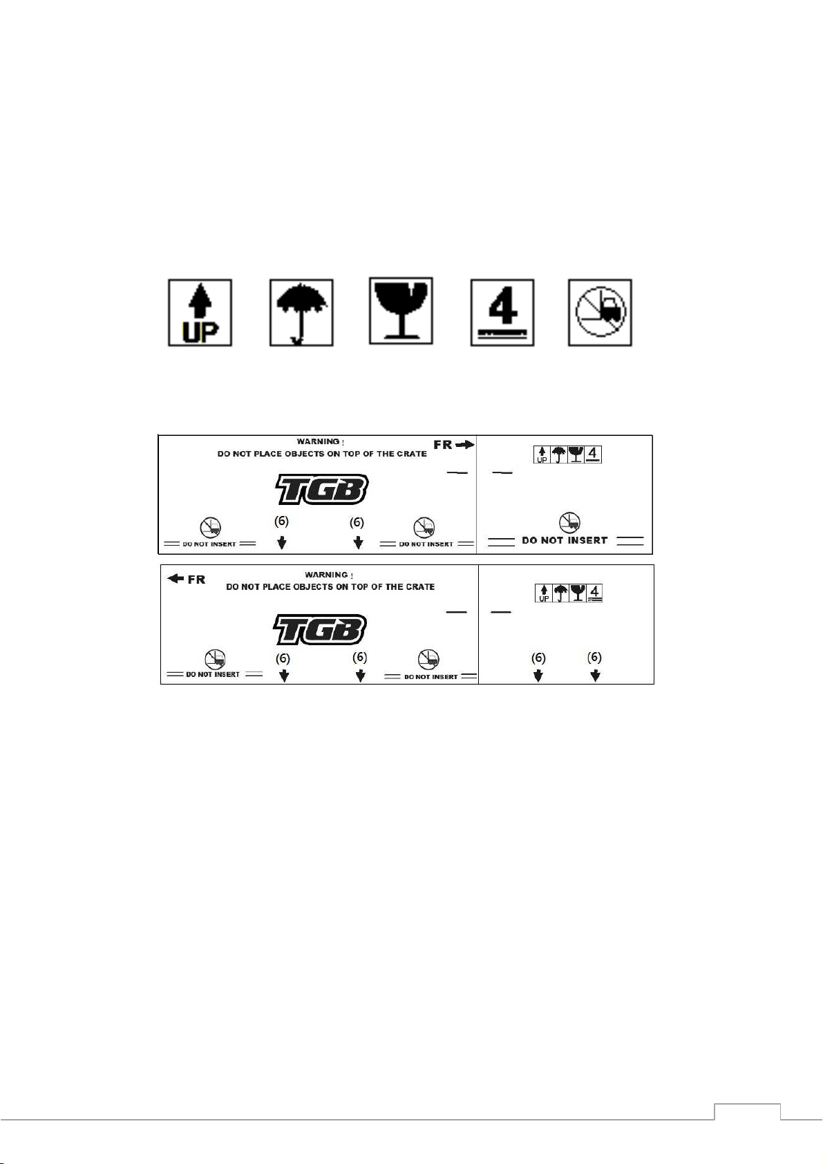
Symbols Used on Outer Cover
(1) Indicates correct upright position of the transport pac age.
(2) Transport pac age must be ept away from rain.
(3) Contents of the transport pac age are fragile, therefore the pac age must be handled with care.
(4) Up to 4 of the transport pac ages can be piled up.
(5) Do not insert from the symbol position of the transport pac age.
(6) Indicates correct insert position of the transport pac age.
(1)
(2)
(3)
(4)
(5)

5
Crate Handling
Warning
1. Always handling the crated vehicle by a for lift, include stac ing/un-stac ing and storing.
2. Never stac ing up over the indicated high shown on the crate outer cover.
Caution
1.
Insert the for according to the indication position where shown on the crate outer cover.
2. Insert the for as shown below, the for must be horizontal into the crate pallet. The operation
with angles will damage the vehicle and created components.
Uncrating
Warning
Crates have sharp edges and may have nails or screws that can cause cuts and injury. Always wear
protective gloves, boots and eye protection when uncrating to prevent injury.
1. Remove 4 corner cage ends (A), and rivets
(B), and then remove the outer cover.
A
B
This manual suits for next models
2
Table of contents
Popular Utility Vehicle manuals by other brands


Cushman
Cushman Turf Truckster 84069 Parts & maintenance manual

Landoll
Landoll 900D Series Operator's manual

Westward
Westward Go-4 XTR Operator's manual

Club Car
Club Car Carryall I 1999 owner's manual

Etnyre
Etnyre Street Flusher operation, maintenance, parts and safety manual

Landoll
Landoll 340 Operator's manual