TGM FOREST ON/OFF Series User manual

FORESTONOFF SERIES
SERVICE MANUAL


Contents
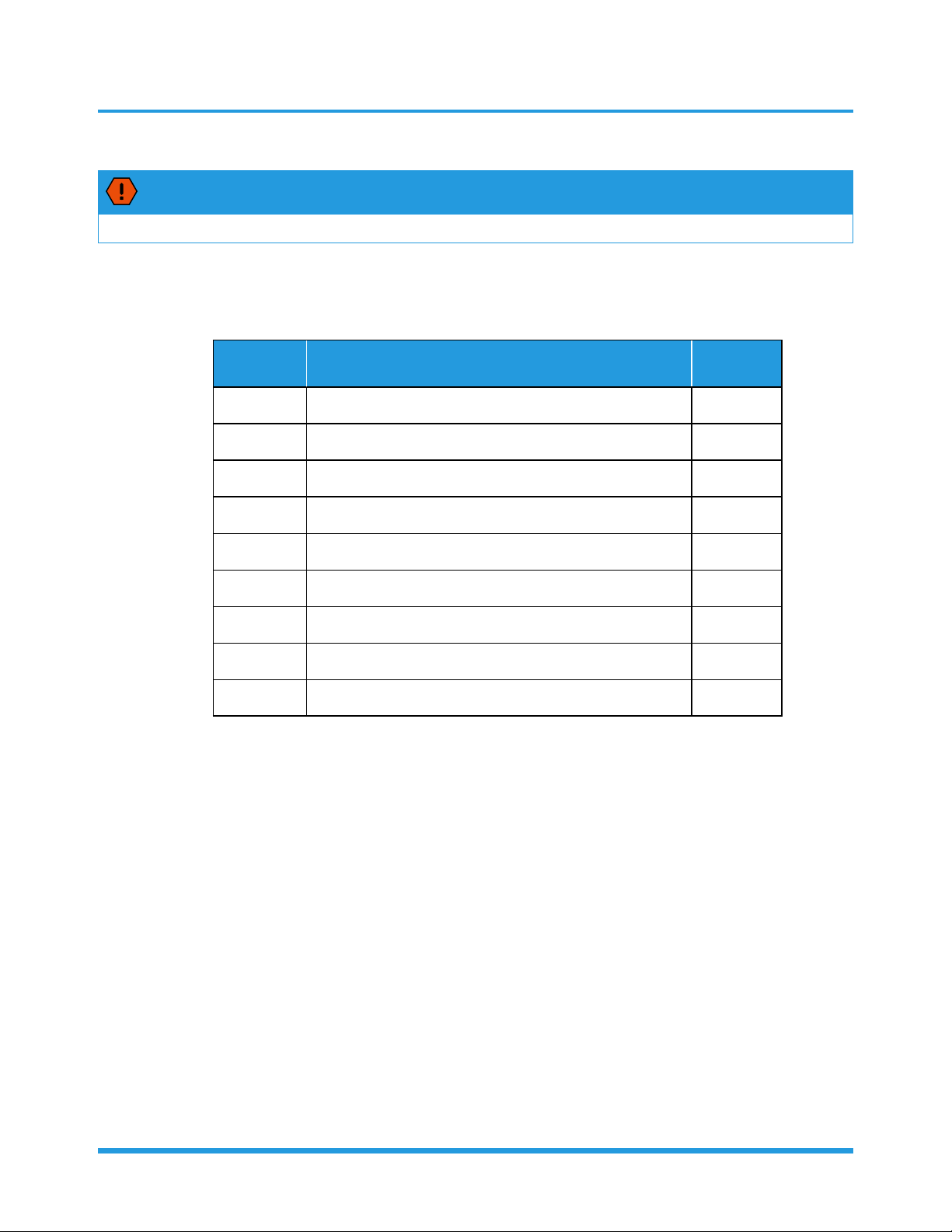
1. Safety Caution .......................................................................................................2
2. General Troubleshooting ......................................................................................3
3. Complain Record Form ..........................................................................................4
4. Information Inquiry ...............................................................................................6
5. Error Diagnosis and Troubleshooting Without Error Code.................................7
5.1 Remote maintenance.....................................................................................7
5.2 Field maintenance .........................................................................................8
6. Quick Maintenance by Error Code........................................................................9
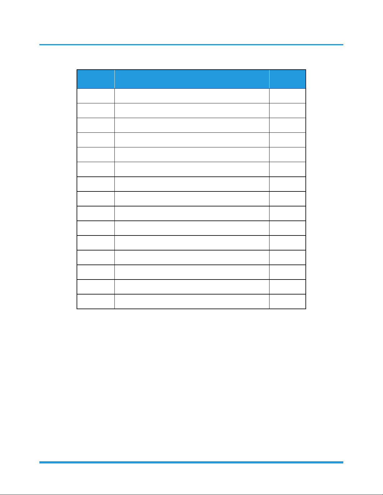
7. Troubleshooting by Error Code...........................................................................14
7.1 EH 00 (EEPROM parameter error diagnosis and solution) .............................14
7.2 EL 01 (Indoor and outdoor unit communication diagnosis and solution).......15
7.3 EH 02 (Zero-crossing detection error diagnosis and solution)........................17
7.4 EH 03/F5/EC 07 (Fan speed is operating outside of the normal range diagnosis
and solution) ...............................................................................................18
7.5 EH 60/EH 61/EC 52 (Open circuit or short circuit of temperature sensor diagnosis
and solution) ...............................................................................................21
7.6 EH 0b (Indoor PCB/display board communication error diagnosis and solution)22
7.7 EL 0C (Refrigerant leakage detection diagnosis and solution) .......................23
7.8 PC 03 (High pressure protection) .................................................................24
8. Check Procedures.................................................................................................25
Troubleshooting

Troubleshooting 2
1. Safety Caution
WARNING
Be sure to turn off all power supplies or disconnect all wires to avoid electric shock.
While checking indoor/outdoor PCB, please equip oneself with antistatic gloves or wrist
strap to avoid damage to the board.
WARNING
Electricity remains in capacitors even when the power supply is off.
Ensure the capacitors are fully discharged before troubleshooting.
Test the voltage between the two pins of the compressor capacitor. If the voltage is zero, the capacitors are fully
discharged.
Note: This picture is for reference only. Actual appearance may vary.

Troubleshooting 3
2. General Troubleshooting
2.1 Error Display (Indoor Unit)
When the indoor unit encounters a recognized error, the operation lamp will flash in a corresponding series, the timer
lamp may turn on or begin flashing, and an error code will be displayed. These error codes are described in the following
tables:
Operation
Lamp
Timer
Lamp Display Error Information Solution
1 time OFF Eh 00 Indoor unit EEPROM parameter error TS14
2 times OFF EL 01 Indoor / outdoor unit communication error(for some models) TS15
3 times OFF EH 02 Zero-crossing signal detection error TS17
4 times OFF EH 03 The indoor fan speed is operating outside of the normal range TS18
6 times OFF EH 60 Indoor room temperature sensor T1 is in open circuit or has short
circuited TS21
6 times OFF EH 61 Evaporator coil temperature sensor T2 is in open circuit or has short
circuited TS21
9 times OFF EH 0 Communication error between display board and main board TS22
8 times OFF EL 0C Refrigerant leak detected TS23
5 times OFF EC 52 Condenser coil temperature sensor T3 or Outdoor room temperature
sensor T4 is in open circuit or has short circuited(for some models) TS21
12 times OFF EC 07 The outdoor fan speed is operating outside of the normal range (for
some models) TS18
7 times FLASH PC 03 High pressure protection(for some models) TS24
For other errors:
The display board may show a garbled code or a code undefined by the service manual. Ensure that this code is not a
temperature reading.
Troubleshooting:
Test the unit using the remote control. If the unit does not respond to the remote, the indoor PCB requires replacement.
If the unit responds, the display board requires replacement.

Troubleshooting 4
3. Complain Record Form
Complain Record Form
Request No.: Date:
Installation Date: Service Date:
Customer Information
Name Telephone No.
Home Address
Email
Product Information
Indoor Unit Model Outdoor Unit Model
Serial No. of indoor unit
Serial No. of outdoor unit
Working Mode □Cooling □Heating □Fan only □Dry
Setting temperature °C / °F Fan speed □Turbo □High □Medium □Low
□Auto
Temperature of air inlet °C / °F Temperature of air
outlet °C / °F
Installation / Condition Information
Indoor temperature °C / °F Indoor humidity %RH
Outdoor temperature °C / °F Outdoor humidity %RH
Length of Connecting pipe Pipe diameter Gas pipe: Liquid pipe:
Length of Wiring wire diameter
System Running Pressure MPa or Bar or PSI
Room size (L*W*H)
Photo of Installation of In-
door unit
(Photo #1)
Photo of Installation
of Outdoor unit
(Photo #2)
Failure Description
Error Code of Indoor unit Code of Outdoor
PCB
Unit does not start
Remote control does not work
Indoor display shows nothing
No cooling or heating at all
Less cooling or heating
Unit starts but stops shortly
High noise
High vibration

Troubleshooting 5
Parameter Checking information by Remote controller
Displaying code Displaying code meaning Display value Display value meaning
T1 Room temperature
T2 Indoor coil temperature
T3 Outdoor coil temperature
Approval from Manufacturer
□Approved
□More Proof needed
□Rejected

Troubleshooting 6
4. Information Inquiry
• To enter information inquiry status, complete the following procedure within ten seconds:
• Press LED(or DO NOT DISTURB) 3 times.
• Press SWING(or AIR DIRECTION) 3 times.
• Finish 1 and 2 within 10 seconds, you will hear beeps for two seconds, which means the unit goes into parameter
checking mode.
• Use the LED(or DO NOT DISTURB) and SWING(or AIR DIRECTION) buttons to cycle through information displayed.
• Pressing LED(or DO NOT DISTURB) will display the next code in the sequence. Pressing SWING(or AIR DIRECTION) will
show the previous.
• The following table shows information codes. The screen will display this code for two seconds, then the information
for 25 seconds.
Displayed code Explanation Displayed
value Meaning Additional Notes
T1 Room temperature
-14—70 -14—70
1. All displayed temperatures
use actual values.
2. All temperatures are
displayed in °C regardless
of remote used.
3. If the actual value exceeds
the range, it will display
the maximum value or
minimum value.
T2 Indoor coil
temperature
T3 Outdoor coil
temperature

Troubleshooting 7
5. Error Diagnosis and Troubleshooting Without Error Code
WARNING
Be sure to turn off unit before any maintenance to prevent damage or injury.
5.1 Remote maintenance
SUGGESTION: When troubles occur, please check the following points with customers before field maintenance.
No. Problem Solution
1 Unit will not start TS10 - TS11
2 The power switch is on but fans will not start TS10 - TS11
3 The temperature on the display board cannot be set TS10 - TS11
4 Unit is on but the wind is not cold(hot) TS10 - TS11
5 Unit runs, but shortly stops TS10 - TS11
6 The unit starts up and stops frequently TS10 - TS11
7 Unit runs continuously but insufficient cooling(heating) TS10 - TS11
8 Cool can not change to heat TS10 - TS11
9 Unit is noisy TS10 - TS11

Troubleshooting 8
5.2 Field maintenance
Problem Solution
1 Unit will not start TS12 - TS13
2 Compressor will not start but fans run TS12 - TS13
3 Compressor and condenser (outdoor) fan will not start TS12 - TS13
4Evaporator (indoor) fan will not start TS12 - TS13
5 Condenser (Outdoor) fan will not start TS12 - TS13
6 Unit runs, but shortly stops TS12 - TS13
7 Compressor short-cycles due to overload TS12 - TS13
8 High discharge pressure TS12 - TS13
9 Low discharge pressure TS12 - TS13
10 High suction pressure TS12 - TS13
11 Low suction pressure TS12 - TS13
12 Unit runs continuously but insufficient cooling TS12 - TS13
13 Too cool TS12 - TS13
14 Compressor is noisy TS12 - TS13
15 Horizontal louver can not revolve TS12 - TS13

Troubleshooting 9
6. Quick Maintenance by Error Code
If you do not have the time to test which specific parts are faulty, you can directly change the required parts according
the error code.
You can find the parts to replace by error code in the following table.
Part requiring replacement
Error Code
EH 00 EL 01 EH 02 EH 03 EH 60
Indoor PCB
Outdoor PCB x x x x
Indoor fan motor xxx x
Outdoor fan motor xxxxx
T1 sensor xxxx
T2 Sensor xxxxx
T3 Sensor xxxxx
Display Board xxxxx
Additional refrigerant xxxxx
Part requiring replacement EH 61 EH 0bEL 0C EC 52 EC 07 PC 03
Indoor PCB x
Outdoor PCB xxxxx
Indoor fan motor xxxxxx
Outdoor fan motor xxxx x
T2 Sensor x x x x
T3 Sensor x x x x x
Display Board x x x x x
Additional refrigerant x x x x
Compressor x x x x x
Capacitor of compressor x x x x x
Capacitor of fan motor x x x x x
System blockages xxxxx
Dirty condenser xxxxx

Troubleshooting 10
1.Remote Maintenance
Possible causes of trouble
Power failure
The main power tripped
Loose connections
Faulty transformer
The voltage is too high or too low
The remote control is powered off
Broken remote control
Dirty air filter
Dirty condenser fins
The setting temperature is higher/lower than the room's(cooling/heating)
The ambient temperature is too high/low when the mode is cooling/heating
Fan mode
SILENCE function is activated(optional function)
Frosting and defrosting frequently
Unit wi l l not s tart
The power s witch i s on but fans wi l l not start
The tempera ture on the di s pl ay boa rd cannot be set
Unit i s on but the wi nd i s not cold(hot)
Unit runs , but shortly stops
The unit s tarts up and s tops frequentl y
Unit runs continuousl y but i ns uffi ci ent cool ing(heating)
Cool can not change to heat
Unit i s noi s y
Test method / remedy
Test voltage
Close the power switch
Inspect connections - tighten
Change the transformer
Test voltage
Replace the battery of the remote control
Replace the remote control
Clean or replace
Clean
Adjust the setting temperature
Turn the AC later
Adjust to cool mode
Turn off SILENCE function.
Turn the AC later
Refrigerant Circuit
Electrical Circuit

Troubleshooting 11
1.Remote Maintenance
Possible causes of trouble
Heavy load condition
Loosen hold down bolts and / or screws
Bad airproof
The air inlet or outlet of either unit is blocked
Interference from cell phone towers and remote boosters
Shipping plates remain attached
Unit wi l l not s tart
The power s witch i s on but fans wi l l not start
The tempera ture on the di s pl ay boa rd cannot be set
Unit i s on but the wi nd i s not cold(hot)
Unit runs , but shortly stops
The unit s tarts up and s tops frequentl y
Unit runs continuousl y but i ns uffi ci ent cool ing(heating)
Cool can not change to heat
Unit i s noi s y
Test method / remedy
Check heat load
Tighten bolts or screws
Close all the windows and doors
Remove the obstacles
Reconnect the power or press ON/OFF button on remote control to restart operation
Remove them
Others

Troubleshooting 12
2.Field Maintenance
Possible causes of trouble
Compressor stuck
Shortage of refrigerant
Restricted liquid line
Dirty air filter
Dirty evaporator coil
Insufficient air through evaporator coil
Overcharge of refrigerant
Dirty or partially blocked condenser
Air or incompressible gas in refrigerant cycle
Short cycling of condensing air
High temperature condensing medium
Insufficient condensing medium
Broken compressor internal parts
Inefficient compressor
Expansion valve obstructed
Expansion valve or capillary tube closed completely
Leaking power element on expansion valve
Poor installation of feeler bulb
Heavy load condition
Loosen hold down bolts and / or screws
Shipping plates remain attached
Poor choices of capacity
Contact of piping with other piping or external plate
Unit wil l not start
Compressor will not start but fans run
Compressor and condenser (outdoor) fan will not
start
Evaporator (i ndoor) fan wil l not start
Condenser (Outdoor) fan will not start
Unit runs , but shortl y s tops
Compressor short-cycles due to overload
High discharge pressure
Low discharge pres s ure
High suction pressure
Low s ucti on pressure
Unit runs conti nuous l y but i ns uffici ent cool i ng
Too cool
Compressor is noisy
Horizontal louver can not revol ve
Test method / remedy
Replace the compressor
Leak test
Replace restricted part
Clean or replace
Clean coil
Check fan
Change charged refrigerant volume
Clean condenser or remove obstacle
Purge, evacuate and recharge
Remove obstruction to air flow
Remove obstruction in air or water flow
Replace compressor
Test compressor efficiency
Replace valve
Replace valve
Replace valve
Fix feeler bulb
Check heat load
Tighten bolts or screws
Remove them
Choose AC of lager capacity or add the number of AC
Rectify piping so as not to contact each other or with external
plate
Refrigerant Circuit
Others

Troubleshooting 13
2.Field Maintenance
Possible causes of trouble
Power failure
Blown fuse or varistor
Loose connections
Shorted or broken wires
Safety device opens
Faulty thermostat / room temperature sensor
Wrong setting place of temperature sensor
Faulty transformer
Shorted or open capacitor
Faulty magnetic contactor for compressor
Faulty magnetic contactor for fan
Low voltage
Faulty stepping motor
Shorted or grounded compressor
Shorted or grounded fan motor
Unit wil l not s tart
Compressor will not start but fans run
Compressor and condenser (outdoor) fan will not start
Evaporator (i ndoor) fa n wi l l not s tart
Condenser (Outdoor) fan will not start
Unit runs , but shortly stops
Compressor short-cycles due to overload
High discharge pressure
Low discharge pressure
High suction pressure
Low s ucti on pressure
Unit runs conti nuousl y but i ns uffi cient cool i ng
Too cool
Compressor is noisy
Horizontal louver can not revolve
Test method / remedy
Test voltage
Inspect fuse type & size
Inspect connections - tighten
Test circuits with tester
Test continuity of safety device
Test continuity of thermostat / sensor & wiring
Place the temperature sensor at the central of the air inlet
grille
Check control circuit with tester
Check capacitor with tester
Test continuity of coil & contacts
Test voltage
Replace the stepping motor
Check resistance with multimeter
Electrical Circuit

Troubleshooting 14
7. Troubleshooting by Error Code
7.1 EH 00 (Indoor EEPROM parameter error diagnosis and solution)
Description: Indoor PCB main chip does not receive feedback from EEPROM chip.
Recommended parts to prepare:
• Indoor PCB
Troubleshooting and repair:
Shut off the power supply and
turn it on 2 minutes later.
Is it still displaying
the error code?
YES
Replace the indoor main
PCB.
The unit is operating normally. NO
Remarks:
EEPROM: A read-only memory whose contents can be erased and reprogrammed using a pulsed voltage.
The location of the EEPROM chip on the indoor PCB is shown in the following image:
Note: The picture and the value are only for reference, actual condition and specific value may vary.

Troubleshooting 15
7.2 EL 01 (Indoor / outdoor unit communication error diagnosis and solution)
Description: The indoor unit has not received feedback from the outdoor unit for 110 seconds, four consecutive times
Recommended parts to prepare:
• Indoor PCB
• Outdoor PCB
• Reactor
Troubleshooting and repair:
Power off, then restart the unit after 2 minutes.
Does a problem remain? The unit is operating normally
NO
Measure Vs. (Vs is the voltage between S and N of
outdoor unit. Red pan-S, Black pan-N)
YES
Is the voltage moving
alternately between Positive and
negative?
Check the outdoor wiring connection.
Is it normal?
Check the reactor.
YES
Is it normal?
Replace the outdoor PCB.
Power on.
YES
Is the error
resolved?
Replace the indoor PCB.
NO
Replace the
reactor NO
Check the indoor wiring
connections
Is it normal?
Replace the indoor PCB.
Power on.
YES
Is the error resolved?
Replace the outdoor PCB.
NO
The voltage moves alternately with
positive value.
NO
The voltage is a
certain value
NO

Troubleshooting 16
Remarks:
• Use a multimeter to test the DC voltage between 2 port(or S or L2 port) and 3 port(or N or S port) of outdoor unit.
The red pin of multimeter connects with 2 port(or S or L2 port) while the black pin is for 3 port(or N or S port) .
When AC is normal running, the voltage will move alternately between -25V to 25V.
• If the outdoor unit has malfunction, the voltage will move alternately with positive value.
• While if the indoor unit has malfunction, the voltage will be a certain value.
• Use a multimeter to test the resistance of the reactor which does not connect with capacitor.
• The normal value should be around zero ohm. Otherwise, the reactor must have malfunction.
Note: The picture and the value are only for reference, actual condition and specific value may vary.

Troubleshooting 17
7.3 EH 02 (Zero crossing detection error diagnosis and solution)
Description: When PCB does not receive zero crossing signal feedback for 4 minutes or the zero crossing signal time
interval is abnormal.
Recommended parts to prepare:
• Connection wires
• Indoor PCB
Troubleshooting and repair:
Check the connections and
power supply.
Correct the connections. Turn on the
unit when the power supply is good.
NO
Indoor main PCB is defective. Replace
indoor main PCB.
YES
Is it normal?
Note: E2/EH 02 zero crossing detection error is only valid for the unit with AC fan motor,
for other models, this error is invalid.
S and N
or
L2 and S
or
2 and 3

Troubleshooting 18
7.4 EH 03 /EC 07 (Fan speed is operating outside of the normal range diagnosis and
solution)
Description: When indoor fan speed keeps too low (300RPM) for certain time, the LED displays the failure code and AC
turns off.
Recommended parts to prepare:
• Connection wires
• Fan assembly
• Fan motor
• PCB
Troubleshooting and repair:
YES
Power off, then restart the unit after 2 minutes.
Is it within normal parameters?
Replace the fan motor
Does a problem remain? The unit is operating normallyNO
Shut off the power supply, Rotate
the fan by hand.
YES
Does it turn easily? Find the cause of the problem and resolve itNO
Check the wiring of fan motor.
YES
Is it improperly wired? Ensure proper connections
Measure the voltage for
the fan motor from the PCB.
YES
Replace the manr PCBNO
Table of contents
Other TGM Air Conditioner manuals
Popular Air Conditioner manuals by other brands

Soleus Air
Soleus Air KC-15U owner's manual

Lloyd
Lloyd LS18HC user manual

intensity
intensity IDUFCI60KC-3 installation manual

Mitsubishi Electric
Mitsubishi Electric Mr.Slim MSZ-A24NA operating instructions

Panasonic
Panasonic CS-WU12VKYF Series operating instructions

Daikin
Daikin Super Multi Plus E-Series CTXG50EV1BW user manual