Thales 82166 Series Manual

86, Bushey Road
Raynes Park, London
SW20 0JW
Tel: +44 (0)20 8946 8011
Fax: +44 (0)20 8946 7530
1
Jul 2008
Revision No. 00
First Issue: Jul 2008
© THALES AVIONICS Ltd. This document and any
information included are the property of Thales Avionics.
They cannot be reproduced, disclosed or utilized without the
company’s prior written approval
INSTALLATION AND MAINTENANCE
MANUAL
Flange Mounted High Power Amplifier
(FMHPA)
82166 Series

Installation Maintenance Manual
FMHPA 82166A30
2
Jul 2008
© THALES AVIONICS Ltd. This document and any
information included are the property of Thales Avionics.
They cannot be reproduced, disclosed or utilized without the
company’s prior written approval
THIS PAGE INTENTIONALLY BLANK

Installation Maintenance Manual
FMHPA 82166
i
Jul 2008
© THALES AVIONICS Ltd. This document and any
information included are the property of Thales Avionics.
They cannot be reproduced, disclosed or utilized without the
company’s prior written approval
Section 1 INTRODUCTION Page
1.1. Purpose of Manual . . . . . . . . . . . . . . . . . . . . . . . . . . . . . . . . . . . . . . . . . . . . . . 1-1
1.2. Scope of Manual . . . . . . . . . . . . . . . . . . . . . . . . . . . . . . . . . . . . . . . . . . . . . . . . 1-2
1.3. Reference documents . . . . . . . . . . . . . . . . . . . . . . . . . . . . . . . . . . . . . . . . . . . . 1-2
1.4. Compliance to Regulations . . . . . . . . . . . . . . . . . . . . . . . . . . . . . . . . . . . . . . . . 1-2
A. Federal Communication Commission . . . . . . . . . . . . . . . . . . . . . . . . . . . . . 1-2
B. European Aviation Safety Agency. . . . . . . . . . . . . . . . . . . . . . . . . . . . . . . . 1-3
Section 2 DESCRIPTION Page
2.1. FMHPA SYSTEM General Description . . . . . . . . . . . . . . . . . . . . . . . . . . . . . . . 2-1
A. Hardware. . . . . . . . . . . . . . . . . . . . . . . . . . . . . . . . . . . . . . . . . . . . . . . . . . . 2-1
(1) RF SRU . . . . . . . . . . . . . . . . . . . . . . . . . . . . . . . . . . . . . . . . . . . . . . . . 2-1
(2) Logic SRU. . . . . . . . . . . . . . . . . . . . . . . . . . . . . . . . . . . . . . . . . . . . . . . 2-2
B. Software . . . . . . . . . . . . . . . . . . . . . . . . . . . . . . . . . . . . . . . . . . . . . . . . . . . 2-2
C. General Operation. . . . . . . . . . . . . . . . . . . . . . . . . . . . . . . . . . . . . . . . . . . . 2-3
(1) Functional Modes: . . . . . . . . . . . . . . . . . . . . . . . . . . . . . . . . . . . . . . . . 2-3
D. HPA Module . . . . . . . . . . . . . . . . . . . . . . . . . . . . . . . . . . . . . . . . . . . . . . . . 2-4
E. PSM and CM Module . . . . . . . . . . . . . . . . . . . . . . . . . . . . . . . . . . . . . . . . . 2-4
(1) PSM . . . . . . . . . . . . . . . . . . . . . . . . . . . . . . . . . . . . . . . . . . . . . . . . . . . 2-5
(2) CM . . . . . . . . . . . . . . . . . . . . . . . . . . . . . . . . . . . . . . . . . . . . . . . . . . . . 2-5
F. Operating Environment . . . . . . . . . . . . . . . . . . . . . . . . . . . . . . . . . . . . . . . . 2-6
(1) Normal operating temperature:. . . . . . . . . . . . . . . . . . . . . . . . . . . . . . . 2-6
(2) Cooling:. . . . . . . . . . . . . . . . . . . . . . . . . . . . . . . . . . . . . . . . . . . . . . . . . 2-6
(3) Heat dissipation: . . . . . . . . . . . . . . . . . . . . . . . . . . . . . . . . . . . . . . . . . . 2-6
G. Environment Conditions . . . . . . . . . . . . . . . . . . . . . . . . . . . . . . . . . . . . . . . 2-7
H. Weight and Dimensions . . . . . . . . . . . . . . . . . . . . . . . . . . . . . . . . . . . . . . . 2-7
I. FMHPA Performances . . . . . . . . . . . . . . . . . . . . . . . . . . . . . . . . . . . . . . . 2-11
2.2. Interfaces . . . . . . . . . . . . . . . . . . . . . . . . . . . . . . . . . . . . . . . . . . . . . . . . . . . . . 2-11
A. Aircraft Power Utility Service. . . . . . . . . . . . . . . . . . . . . . . . . . . . . . . . . . . 2-11
B. Communication Interface . . . . . . . . . . . . . . . . . . . . . . . . . . . . . . . . . . . . . 2-12
2.3. FMHPA Interconnect Data. . . . . . . . . . . . . . . . . . . . . . . . . . . . . . . . . . . . . . . . 2-12
A. FMHPA Interconnection Diagram . . . . . . . . . . . . . . . . . . . . . . . . . . . . . . . 2-12
B. FMHPA Connectors . . . . . . . . . . . . . . . . . . . . . . . . . . . . . . . . . . . . . . . . . 2-12
(1) FMHPA Connectors . . . . . . . . . . . . . . . . . . . . . . . . . . . . . . . . . . . . . . 2-12
(2) Connector Designation . . . . . . . . . . . . . . . . . . . . . . . . . . . . . . . . . . . . 2-13
(3) Connector J1 PIN Out. . . . . . . . . . . . . . . . . . . . . . . . . . . . . . . . . . . . . 2-13
Section 3 INSTALLATION GUIDELINES Page
3.1. Introduction . . . . . . . . . . . . . . . . . . . . . . . . . . . . . . . . . . . . . . . . . . . . . . . . . . . . 3-1
3.2. Interchangeability . . . . . . . . . . . . . . . . . . . . . . . . . . . . . . . . . . . . . . . . . . . . . . . 3-1
3.3. FMHPA Location and Accessibility Guidelines . . . . . . . . . . . . . . . . . . . . . . . . . 3-1
3.4. Cooling . . . . . . . . . . . . . . . . . . . . . . . . . . . . . . . . . . . . . . . . . . . . . . . . . . . . . . . 3-2
3.5. Power Requirements . . . . . . . . . . . . . . . . . . . . . . . . . . . . . . . . . . . . . . . . . . . . . 3-2
3.6. Bonding Requirements . . . . . . . . . . . . . . . . . . . . . . . . . . . . . . . . . . . . . . . . . . . 3-3

Installation Maintenance Manual
FMHPA 82166
ii
Jul 2008
© THALES AVIONICS Ltd. This document and any
information included are the property of Thales Avionics.
They cannot be reproduced, disclosed or utilized without the
company’s prior written approval
Section 4 INSPECTION AND SYSTEM CHECKOUT Page
4.1. Inspection/Check Procedure . . . . . . . . . . . . . . . . . . . . . . . . . . . . . . . . . . . . . . . 4-1
A. Wiring . . . . . . . . . . . . . . . . . . . . . . . . . . . . . . . . . . . . . . . . . . . . . . . . . . . . . 4-1
B. FMHPA . . . . . . . . . . . . . . . . . . . . . . . . . . . . . . . . . . . . . . . . . . . . . . . . . . . . 4-1
4.2. System checkout . . . . . . . . . . . . . . . . . . . . . . . . . . . . . . . . . . . . . . . . . . . . . . . . 4-2
A. Post-Installation Test. . . . . . . . . . . . . . . . . . . . . . . . . . . . . . . . . . . . . . . . . . 4-2
Section 5 FAULT ISOLATION Page
5.1. Bite Function . . . . . . . . . . . . . . . . . . . . . . . . . . . . . . . . . . . . . . . . . . . . . . . . . . . 5-1
5.2. BITE Test. . . . . . . . . . . . . . . . . . . . . . . . . . . . . . . . . . . . . . . . . . . . . . . . . . . . . . 5-1
A. Self Test . . . . . . . . . . . . . . . . . . . . . . . . . . . . . . . . . . . . . . . . . . . . . . . . . . . 5-1
B. Health Monitor. . . . . . . . . . . . . . . . . . . . . . . . . . . . . . . . . . . . . . . . . . . . . . . 5-2
5.3. SDU LED . . . . . . . . . . . . . . . . . . . . . . . . . . . . . . . . . . . . . . . . . . . . . . . . . . . . . . 5-2
Section 6 MAINTENANCE Practices Page
6.1. General . . . . . . . . . . . . . . . . . . . . . . . . . . . . . . . . . . . . . . . . . . . . . . . . . . . . . . . 6-1
6.2. Equipment and Materials . . . . . . . . . . . . . . . . . . . . . . . . . . . . . . . . . . . . . . . . . . 6-1
6.3. Procedure for the FMHPA . . . . . . . . . . . . . . . . . . . . . . . . . . . . . . . . . . . . . . . . . 6-2
A. Removal and Installation Procedure . . . . . . . . . . . . . . . . . . . . . . . . . . . . . . 6-2
(1) Remove the FMHPA as follows: . . . . . . . . . . . . . . . . . . . . . . . . . . . . . . 6-2
(2) Install the FMHPA as follows: . . . . . . . . . . . . . . . . . . . . . . . . . . . . . . . . 6-2
B. Adjustment Procedure. . . . . . . . . . . . . . . . . . . . . . . . . . . . . . . . . . . . . . . . . 6-4
C. Repair Procedure . . . . . . . . . . . . . . . . . . . . . . . . . . . . . . . . . . . . . . . . . . . . 6-4
D. Return to Service Procedures . . . . . . . . . . . . . . . . . . . . . . . . . . . . . . . . . . . 6-4
6.4. Cleaning of Mechanical Parts . . . . . . . . . . . . . . . . . . . . . . . . . . . . . . . . . . . . . . 6-5
6.5. Periodic Checks. . . . . . . . . . . . . . . . . . . . . . . . . . . . . . . . . . . . . . . . . . . . . . . . . 6-5
6.6. Cabling and Connections. . . . . . . . . . . . . . . . . . . . . . . . . . . . . . . . . . . . . . . . . . 6-5
6.7. Instructions for Continued Airworthiness . . . . . . . . . . . . . . . . . . . . . . . . . . . . . . 6-5

Installation Maintenance Manual
FMHPA 82166
iii
Jul 2008
© THALES AVIONICS Ltd. This document and any
information included are the property of Thales Avionics.
They cannot be reproduced, disclosed or utilized without the
company’s prior written approval
RECORD OF REVISIONS
Revision
No:
Revision
Date
Date
Inserted
By Revision
No:
Revision
Date
Date
Inserted
By

Installation Maintenance Manual
FMHPA 82166
iv
Jul 2008
© THALES AVIONICS Ltd. This document and any
information included are the property of Thales Avionics.
They cannot be reproduced, disclosed or utilized without the
company’s prior written approval
THIS PAGE INTENTIONALLY BLANK

Installation Maintenance Manual
FMHPA 82166
1-1
Jul 2008
© THALES AVIONICS Ltd. This document and any
information included are the property of Thales Avionics.
They cannot be reproduced, disclosed or utilized without the
company’s prior written approval
SECTION 1
10000INTRODUCTION
1.1. PURPOSE OF MANUAL
This manual sets forth installation and maintenance guidelines for the THALES
TopFlight Satcom (TFS) Flange-mounted High Power Amplifier (FMHPA). The
FMHPA installation specific and general guidelines contained within this manual are
supported by mechanical and electrical interconnection drawings. Drawings should be
reviewed by the installation organisation, and any requirements specific to a particular
airframe should be assessed before installation is commenced.
The Manual covers the following topics:
a. Title Page.
b. Table of Content.
c. Record of Revisions
d. Introduction.
e. Description.
f. Installation Guidelines.
g. Inspection and System Checkout.
h. Fault Isolation.
i. Maintenance Practices.
NOTE: This manual does not cover aircraft system commissioning test
procedures.
Advisory notes presented within this manual such as: ‘Warnings, Cautions and Notes’
are applicable to the TFS system as follows:
a. A WARNING is used to alert the reader to possible hazard which may
cause loss of life or physical injury.
b. A CAUTION is used to denote the possibility of damage to materiel but
not danger to personnel.
c. A NOTE is used to convey, or draw attention to, information that is
extraneous to the immediate subject of the text.

Installation Maintenance Manual
FMHPA 82166
1-2
Jul 2008
© THALES AVIONICS Ltd. This document and any
information included are the property of Thales Avionics.
They cannot be reproduced, disclosed or utilized without the
company’s prior written approval
For any queries related to information contained within this Manual contact the
following:
THALES TFS Project Manager
86 Bushey Road
Raynes Park, London
SW20 0JW, UK
Tel. +44 (0)20 8946 8011
Fax. +44 (0)20 8946 7530
1.2. SCOPE OF MANUAL
The Thales FMHPA comply with the design requirements set forward in the ARINC 781
Characteristic. An ARINC 781 compliant system is intended to support one or more of
the Inmarsat aeronautical services known as ‘Classic-Aero’, ‘Swift 64’, and
‘SwiftBroadband’.
This manual provides information specific for the FMHPA.
1.3. REFERENCE DOCUMENTS
The following publications provide additional useful information:
Table 1.1 Reference Documents
1.4. COMPLIANCE TO REGULATIONS
A. Federal Communication Commission
The FMHPA is designed to be compliant with part 15 and part 87 of the Federal
Communication Commission (FCC) regulations
THALES FMHPA Component Maintenance Manual
THALES SDU Component Maintenance Manual Airbus:44-35-32
Boeing: TBD
EMS AMT-3800 High Gain Antenna Subsystem Installation
Manual
MN-1242-20047
Mark 33 Digital Information Transfer System ARINC 429
Air Transport Avionics Equipment Interfaces ARINC 600
Mark III Aviation Satellite Communication (Satcom) System
Avionics
ARINC 781

Installation Maintenance Manual
FMHPA 82166
1-3
Jul 2008
© THALES AVIONICS Ltd. This document and any
information included are the property of Thales Avionics.
They cannot be reproduced, disclosed or utilized without the
company’s prior written approval
B. European Aviation Safety Agency
The installation must be compliant to the following European Aviation Safety Agency
(EASA) regulations:
• EASA/FAR 25.869 Fire protection systems
• EASA 25X0899 Electrical bonding and protection against lightning and
static electricity
• EASA/FAR 25.1301 Equipment, general, function and installation
• EASA/FAR 25.1309 Equipment, systems and installations
• EASA 25X1316 System lightning protection
• EASA/FAR 25.1353 Electrical equipment and installations
• EASA/FAR 25.1357 Circuit protective devices
• EASA 25X1360 Precautions against injury
• EASA/FAR 25.1431 Electronic equipment
• EASA 25.561 Emergency Landing.

Installation Maintenance Manual
FMHPA 82166
1-4
Jul 2008
© THALES AVIONICS Ltd. This document and any
information included are the property of Thales Avionics.
They cannot be reproduced, disclosed or utilized without the
company’s prior written approval
THIS PAGE INTENTIONALLY BLANK

Installation Maintenance Manual
FMHPA 82166
2-1
Jul 2008
© THALES AVIONICS Ltd. This document and any
information included are the property of Thales Avionics.
They cannot be reproduced, disclosed or utilized without the
company’s prior written approval
SECTION 2
20000DESCRIPTION
2.1. FMHPA SYSTEM GENERAL DESCRIPTION
The FMHPA forms part of the airborne SATCOM system, used in conjunction with a
Satellite Data Unit (SDU), a Diplexer/Low Noise Amplifier (DLNA) and a High Gain
Antenna (HGA) conforming to ARINC 781, with an internal Beam Steering Unit (BSU).
The TopFlight Satcom (TFS) system conforms to the Aeronautical Radio Incorporated
(ARINC) 781 Characteristic, and interfaces with onboard avionics and communication
equipment to provide the aircraft with a range of communication services by
transmitting and receiving L Band signals to and from the fourth generation of
INMARSAT satellites. For this purpose the INMARSAT satellite constellation is
connected to the ground backbone telecommunication network through Satellite Access
Stations (SAS) operated by service providers.
A. Hardware
The FMHPA contains two hardware Shop Replaceable Units (SRU):
• The Radio Frequency (RF) SRU which contains the High Power
Amplifier (HPA) and the RF Filter
• The Logic SRU which contains the Power Supply Module (PSM) and
the Communication Module (CM).
The two SRUs have a heat-skin with cooling fins and a nozzle to dissipate the
temperature.
(1) RF SRU
The RF SRU has two external connectors and two internal connectors:
a. External connectors:
• RF input (J2)
• RF output (J3).
b. Internal connectors, connecting the RF SRU to the Logic SRU:
• Power Supplies
• Communication signal.
Installation Maintenance Manual
FMHPA 82166
2-2
Jul 2008
© THALES AVIONICS Ltd. This document and any
information included are the property of Thales Avionics.
They cannot be reproduced, disclosed or utilized without the
company’s prior written approval
(2) Logic SRU
The Logic SRU has one external connector and six internal connectors:
a. External connector:
The external connector (J1) is used to communicate with the SDU and for the power
supplies of the FMHPA.
b. Internal connectors are used to:
• Connect the PSM and the CM
• Connect the RF SRU to the Logic SRU for power supplies and the
communication signal.
• Supply a test connector for testing and downloading.
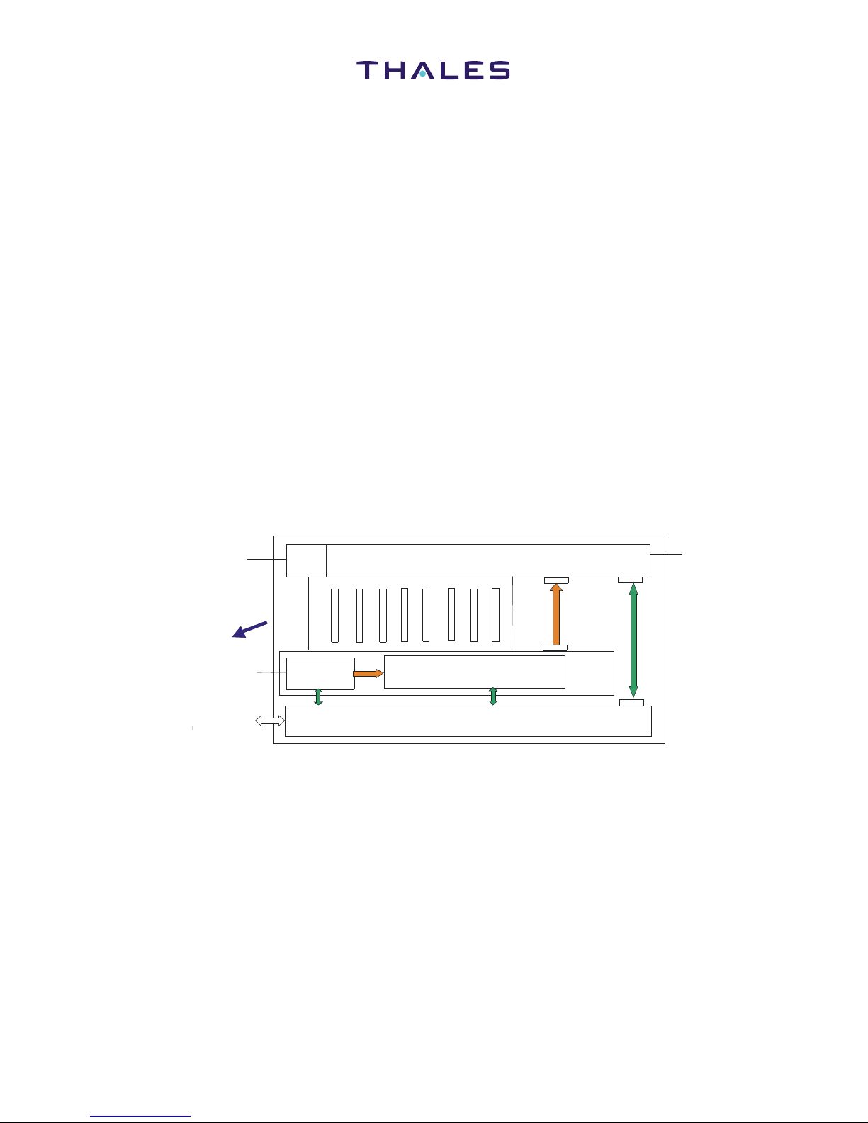
B. Software
There is no software in the FMHPA.
All FMHPA functions shall be allocated to hardware.
Figure 2.1 FMHPA Internal Organisation.
HPA
Power Supply Converters
Command/
Status
Power
Supplies
Communication Module
PSM
115Vac
ARINC 429 I/O
(J1)
Test and
Maintainability
EMC Filter
RF In (J2)
RF Out (J3)
Airflow
Tav_e_0000761_00
RF
FILTER
SRU1:
HPA+
RF Filter
SRU2:
PSM+
CM

Installation Maintenance Manual
FMHPA 82166
2-3
Jul 2008
© THALES AVIONICS Ltd. This document and any
information included are the property of Thales Avionics.
They cannot be reproduced, disclosed or utilized without the
company’s prior written approval
C. General Operation
The FMHPA is a Linear Power Amplifier for embedded communication system (TFS).
FMHPA supplies up to 35W RF power to the Aircraft Satcom antenna when the physical
separation of the SDU and the antenna is such that the RF loss between the SDU and the
antenna will be greater than that allowed in ARINC 781. Alternatively, the FMHPA may
be used in cases where more power is required than would be available from the HPA
within the SDU, to provide the services offered.
Its function is to amplify the modulated signals supplied by the SDU. The number of
signals to be amplified depends on the communication traffic, from a single up to the
maximum capability of the SDU. FMHPA also includes a constant and programmable
RF gain, a high grade of self test (90% of failures are detected) and a high temperature
protection function.
(1) Functional Modes:
The FMHPA operates in the following five modes:
a. Nominal Mode (35W output)
Nominal Mode (NM) is defined as the operating condition when power supplies are
applied. This mode is enabled by default at powerup, the power supply is defined at its
nominal Voltage (around +27V)
b. Low Power mode (9W output)
Low Power Mode is defined as the operating condition which can be enabled by SDU
(or FMHPA in security case) when the temperature is high and in order to reduce the
dissipated power (for example to save the internal temperature when there is a loss of
cooling). For this mode, the power supply is changed from Nominal Voltage (around
+27V) to Low Voltage (around +17V). Cockpit only services available.
With NM and LPM modes, the main characteristic of the modes is to maintain a constant
gain whatever the temperature.
c. Carriers Off/MUTE Mode
This mode switches off the RF gain, and puts the FMHPA in Standby (STBY) mode.
d. STBY / On mode
With Standby mode, the main characteristic of the mode is to have the lowest
consumption.
In this mode, the RF output power equals zero, and the thermal dissipation within the
FMHPA is reduced to the minimum possible to permit temperature monitoring and

Installation Maintenance Manual
FMHPA 82166
2-4
Jul 2008
© THALES AVIONICS Ltd. This document and any
information included are the property of Thales Avionics.
They cannot be reproduced, disclosed or utilized without the
company’s prior written approval
communication with the SDU to continue. This STBY mode can be obtained with four
configurations:
• Command configuration: In this case, an input command, Carriers Off/
Mute command from SDU, enable or disable the STBY mode
• Auto-protection configuration: When FMHPA detect an internal failure
(High level) and the SDU doesn’t answer within 2 seconds
• With carriers Off/Mute, the main characteristic of the mode is to have a
high isolation between FMHPA input and FMHPA output
• After HPA Power-On Self Test (POST) or at the end of a self test.
e. BITE Monitoring
A monitoring Mode is defined in order to check if the FMHPA Status is OK or FAIL.
A self test is carried out at Start-up and on request from the SDU.
D. HPA Module
The HPA function is to amplify modulated signals from the SDU, up to 35 W.
The HPA includes an amplification chain, a digital part for control and communication
and a RF filter.
The output RF filter is a mechanical filter, without any electronic component, with a N
connector output.
E. PSM and CM Module
The PSM and CM SRU module contains two modules in the same housing:
• Power Supply Module
• Communication Module.

Installation Maintenance Manual
FMHPA 82166
2-5
Jul 2008
© THALES AVIONICS Ltd. This document and any
information included are the property of Thales Avionics.
They cannot be reproduced, disclosed or utilized without the
company’s prior written approval
(1) PSM
(2) CM
Its function is to manage the interface with the ARINC 429, to send control signals to the
HPA and the PSM and report FMHPA status.
Figure 2.2 Power Supply Module
J1
Lightening/
EMC
protection
Isolated AC/DC
350W PFC
Hold up
capacitors
200ms for
Digital part
DC/DC HPA
HL/LV voltage
300W
DC/DC
+5,1V - 30W
HPA
CM
J9
J5
DC/DC
-15V - 1.5W
+15V - 1.5W
+5V - 0.1W
+5.1V - 2.5W
Temperature
sensors
Voltage
supervision
Power cut
management
Output
discrets Control
signals
Nominal/Low
Voltage
selection
PSM
P115VAC
N115VAC
ARINC 429
In
ARINC 429
Out
33V
DC
J6
J8
J7
Tav_e_0000767_00

Installation Maintenance Manual
FMHPA 82166
2-6
Jul 2008
© THALES AVIONICS Ltd. This document and any
information included are the property of Thales Avionics.
They cannot be reproduced, disclosed or utilized without the
company’s prior written approval
F. Operating Environment
(1) Normal operating temperature:
Between -15oC (5oF) and +70oC (158oF)
(2) Cooling:
Forced air type requiring Normal airflow rate of 2.6 lb/min (72 kg/hr). Nominal Mode
(NM) inlet temperature +60oC (140o F) and Low Power Mode (LPM) inlet temperature
of +70oC (158oF).
(3) Heat dissipation:
265 W (assuming 100% duty cycles with HPA operating at 35 W output).
Figure 2.3 Communiction Module
Input LRU
Connector
Communication
Module
HPA
PSM
Test Connector
Tav_e_0000768_00
A429 High
speed
A429 Low
speed

Installation Maintenance Manual
FMHPA 82166
2-7
Jul 2008
© THALES AVIONICS Ltd. This document and any
information included are the property of Thales Avionics.
They cannot be reproduced, disclosed or utilized without the
company’s prior written approval
G. Environment Conditions
The FMHPA complies with the RTCA/DO-160. The environmental qualifications
categories complied with, are as per listed refer (Table 2.1).
Table 2.1 Environmental Test categories for SDU and SCM
H. Weight and Dimensions
Weight and dimensions of the FMHPA are as follows:
NOTE: Weights and measurements in this manual use both U.S (inches) and S.I.
(metric: mm) values.
Maximum Weight: 8.9 kg (19.8 lb)
RTCA DO-160 Environmental Categories
Section Condition Category
4.0 Temperature/Altitude A2
5.0 Temp Var B
6.0 Humidity A
7.0 Shock/Crash E
8.0 Vibration R
Vibration Curve C or C1
15.0 Magnetic Effect A
16.0 Power Input A
Harmonics H
17.0 Voltage Spike A
18.0 Conducted Audio Susceptibility K(CF),
K(NF),
K(WF)
19.0 Induced Signal Susceptibility CC
20.0 RF Susceptibility T
21.0 RF Emissions T

Installation Maintenance Manual
FMHPA 82166
2-8
Jul 2008
© THALES AVIONICS Ltd. This document and any
information included are the property of Thales Avionics.
They cannot be reproduced, disclosed or utilized without the
company’s prior written approval
THIS PAGE INTENTIONALLY BLANK
Installation Maintenance Manual
FMHPA 82166
2-9
Jul 2008
© THALES AVIONICS Ltd. This document and any
information included are the property of Thales Avionics.
They cannot be reproduced, disclosed or utilized without the
company’s prior written approval
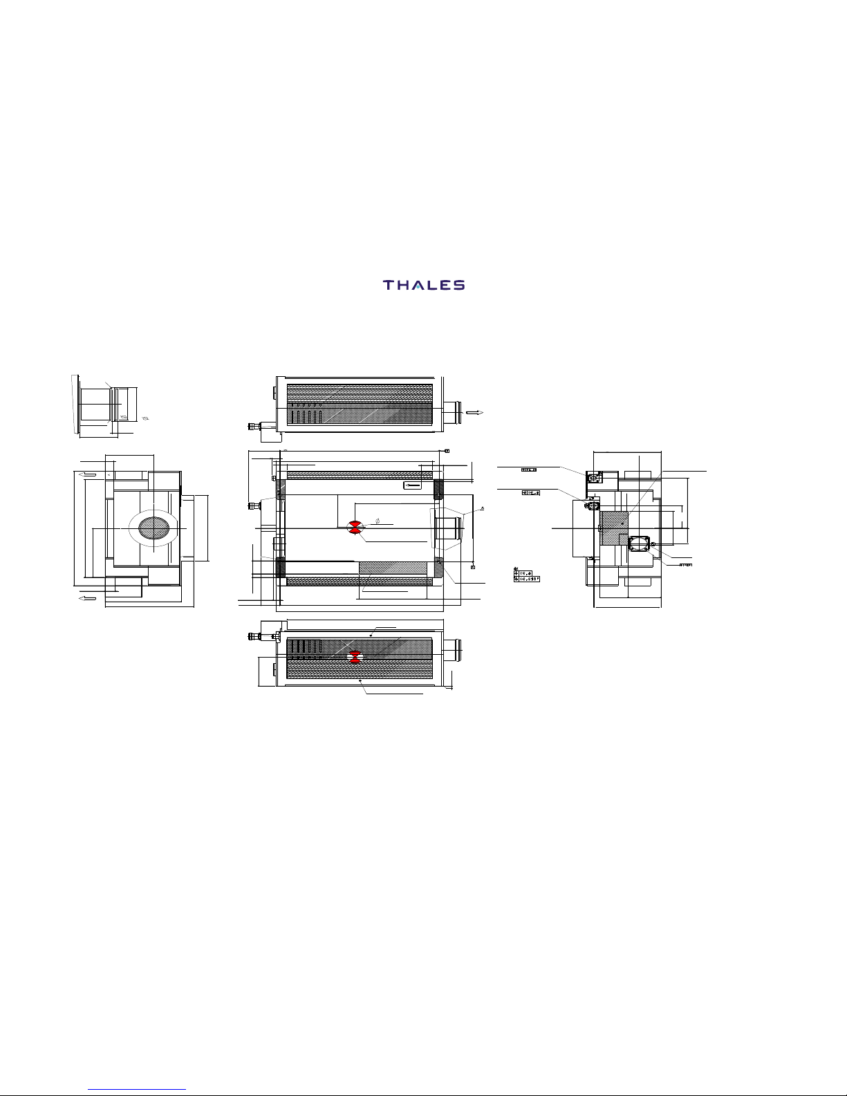
Figure 2.1 FMHPA Overall Dimensions
R3.27 MAXI
(0.13”)
50.9MAXI
(2”)
54.61MAXI
(2.15”)
R1.87 MAXI
(0.07”)
45.8 +/- 0.4
(1.8)
6.35
(0.25”)
14 +/-0.5
(0.551” +/-0.2”)
85.4 +/-2
(3.362” +/-0.079”)
277MAXI
(10.906”)
237MAXI
(9.331”)
TOP
118.5+/-2
(4.665”+/-0/079”)
18 MINI
(0.709”) 65 MAXI
(2.559”)
136.5 MAXI
(5.374”)
158 MAXI
(6.22”)
BOTTOM
159MAXI
(6.26”)
Drawn Air Flow
284.2
(11.189”)
279.5 MAXI
(11.004”)
19.5 MINI
(0.768”)
59 MAXI
(2.323”)
16 MAXI
(0.63”)
79
(3.11”)
150
(5.91”)
30
(1.18”)
CENTER OF GRAVITY
30MAXI
(1.181”)
8MINI
(0.315”)
13.5 MAXI
(0.531”) 36 MAXI
(1.417”)
INTERFACE PC BOARD
120 MAXI
(4.724”)
328.5 MAXI
(12.933”)
299 MAXI
(11.772”) 279 MINI
(10.984”)
HPA
POWER SUPPLY
70
(2.76”)
0.5MINI
(0.0197”)
6.75+/-).1
(0.266”+/-0.004”)
30 MINI
(1.181”)
162.58
(6.4”)
39+/-10
(1.54”+/-0.39”)
5+/-10
(0.2”+/-0.39”)
J2
RF IN (50 ohms)
INTERFACE SERIES TNC SOCKET
CONTACT
J3
RF OUT (50 ohms)
INTERFACE SERIES N SOCKET
CONTACT
116.8
(4.598”)
39.5
(1.56”) DRAWN AIR FLOW
AREA
121.3
(4.776”)
54.25
(2.136”)
80MAXI
(3.15”)
37.5
(1.476”)
MAJOR KEY
J1
55 MAXI
(2.165”)
56 MINI
(2.2”)
160
(4.59”)
NOTE: MAXIMUM PERMISSIBLE TIGHTENING TORQUE OF ATTACHMENT SCREWS = 5.3 N.m (3.9 lbf.ft)

Installation Maintenance Manual
FMHPA 82166
2-10
Jul 2008
© THALES AVIONICS Ltd. This document and any
information included are the property of Thales Avionics.
They cannot be reproduced, disclosed or utilized without the
company’s prior written approval
THIS PAGE INTENTIONALLY BLANK
Table of contents


