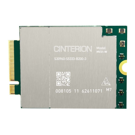
Thales Cinterion MLA31-W User manual

Getting Started with 4G Modem Card
User Guide
Version: 01
DocId: MLx31_startup_guide_v01

GENERAL NOTE
THE USE OF THE PRODUCT INCLUDING THE SOFTWARE AND DOCUMENTATION (THE "PROD-
UCT") IS SUBJECT TO THE RELEASE NOTE PROVIDED TOGETHER WITH PRODUCT. IN ANY
EVENT THE PROVISIONS OF THE RELEASE NOTE SHALL PREVAIL. THIS DOCUMENT CONTAINS
INFORMATION ON THALES PRODUCTS. THE SPECIFICATIONS IN THIS DOCUMENT ARE SUB-
JECT TO CHANGE AT THALES'S DISCRETION. THALES DIS AIS DEUTSCHLAND GMBH GRANTS
A NON-EXCLUSIVE RIGHT TO USE THE PRODUCT. THE RECIPIENT SHALL NOT TRANSFER,
COPY, MODIFY, TRANSLATE, REVERSE ENGINEER, CREATE DERIVATIVE WORKS; DISASSEM-
BLE OR DECOMPILE THE PRODUCT OR OTHERWISE USE THE PRODUCT EXCEPT AS SPECIFI-
CALLY AUTHORIZED. THE PRODUCT AND THIS DOCUMENT ARE PROVIDED ON AN "AS IS" BASIS
ONLY AND MAY CONTAIN DEFICIENCIES OR INADEQUACIES. TO THE MAXIMUM EXTENT PER-
MITTED BY APPLICABLE LAW, THALES DIS AIS DEUTSCHLAND GMBH DISCLAIMS ALL WARRAN-
TIES AND LIABILITIES. THE RECIPIENT UNDERTAKES FOR AN UNLIMITED PERIOD OF TIME TO
OBSERVE SECRECY REGARDING ANY INFORMATION AND DATA PROVIDED TO HIM IN THE
CONTEXT OF THE DELIVERY OF THE PRODUCT. THIS GENERAL NOTE SHALL BE GOVERNED
AND CONSTRUED ACCORDING TO GERMAN LAW.
Copyright
Transmittal, reproduction, dissemination and/or editing of this document as well as utilization of its con-
tents and communication thereof to others without express authorization are prohibited. Offenders will be
held liable for payment of damages. All rights created by patent grant or registration of a utility model or
design patent are reserved.
Copyright © 2021, THALES DIS AIS Deutschland GmbH
Trademark Notice
Thales, the Thales logo, are trademarks and service marks of Thales and are registered in certain coun-
tries.
Microsoft and Windows are either registered trademarks or trademarks of Microsoft Corporation in the
United States and/or other countries.
tMLx31_startup_guide_v01 2021-05-06
Confidential / Prelimenary
Getting Started with 4G Modem Card
2
Page 2 of 17
User Guide: Getting Started with 4G Modem Card
Version: 01
Date: 2021-05-06
DocId: MLx31_startup_guide_v01
Status Confidential / Prelimenary

Getting Started with 4G Modem Card
Contents
17
tMLx31_startup_guide_v01 2021-05-06
Confidential / Prelimenary
Page 3 of 17
Contents
0 Document History ...................................................................................................... 4
1 Introduction ................................................................................................................. 5
1.1 Supported Products ........................................................................................... 5
1.2 Related Documents ........................................................................................... 5
2 Getting Started with 4G Modem Cards ..................................................................... 6
2.1 Technical Requirements .................................................................................... 6
2.2 Connecting MLx31-W to the 4G Modem Card Adapter Board........................... 6
2.3 Start Up the Modem Card .................................................................................. 9
2.3.1 Script based Driver Installation ............................................................. 9
2.3.2 Enter SIM and go Online..................................................................... 10
2.3.3 Reading MLx31-W Properties............................................................. 12
3 Appendix.................................................................................................................... 13
3.1 4G Modem Card Adapter Board ...................................................................... 13
3.1.1 Package Content ................................................................................ 13
3.2 4G Modem Card Adapter Board Description ................................................... 14
3.2.1 USB Variant ........................................................................................ 15
3.3 Power Supply Configuration ............................................................................ 15
3.4 Configuration Switches and Jumper ................................................................ 15
3.5 Additional Connector........................................................................................ 16

Getting Started with 4G Modem Card
1 Introduction
16
tMLx31_startup_guide_v01 2021-05-06
Confidential / Prelimenary
Page 5 of 17
1 Introduction
This document describes a ready-to-use development and test environment for the Thales 4G
Modem Card.
The development and test environment comprises the following hardware components
• 4G Modem Card MLA31-W or MLP31-W
• 4G Modem Card Adapter Board
The purpose of this document1is to guide you through the process of connecting the hardware,
installing the supplied drivers on a Microsoft®Windows 10 system and getting started with 4G
Modem Card.
1.1 Supported Products
This document applies to the following Thales 4G Modem cards:
•Cinterion
®MLA31-W
•Cinterion
®MLP31-W
4G Modem Card in this document refers to all of the above mentioned product variants. Where
necessary a note is made to differentiate between these product variants.
1.2 Related Documents
[1] MLx31-W Hardware Interface Description
1. The document is effective only if listed in the appropriate Release Notes as part of the technical docu-
mentation delivered with your Thales module.

Getting Started with 4G Modem Card
2 Getting Started with 4G Modem Cards
16
tMLx31_startup_guide_v01 2021-05-06
Confidential / Prelimenary
Page 6 of 17
2 Getting Started with 4G Modem Cards
2.1 Technical Requirements
• MLx31-W (for details see Figure 1 and [1])2
• corresponding driver package (USB)
• Computer running Windows 10, USB 3.0 Interface
• Local administrator privileges on the particular Windows computer to install and uninstall
the drivers
• 4G Modem Card Adapter Board USB Variant (for details see Section 3.1)
• Accessories for MLx31-W:
- Two (MLA31-W) / four (MLP31-W) short 50 Ohms RF adapter cables with MHF4 type
connectors to connect the appropriate MHF4 type connectors on the 4G Modem Card
Adapter Board (supplied by Thales)
- Two (MLA31-W) / four (MLP31-W) external 50 Ohms RF antennas with SMA connector
to connect the SMA connector on the 4G Modem Card Adapter Board (supplied by
Thales)
- USB 3.0 cable (supplied by Thales)
• Appropriate application for controlling the module from within a PC’s operating system. For
Windows, e.g. Windows Hyperterminal
• (U)SIM from a UMTS/LTE network provider
2.2 Connecting MLx31-W to the 4G Modem Card Adapter Board
To properly connect the 4G Modem Card and all accessories to the 4G Modem Card Adapter
Board please complete the steps listed below. The complete setup with the 4G Modem Card
mounted onto the 4G Modem Card Adapter Board is shown in Figure 2.
• Ensure that all jumpers and switches on the 4G Modem Card Adapter Board are set to their
positions as shown in Table 2 and Table 3.
• Place Thermo Pad with the self adhesive side (remove protection foil) on the 4G Modem
Card Adapter Board between M.2 Connector and retention screw whole for 42mm cards.
• Insert the 4G Modem Card into the M.2 connector on the 4G Modem Card Adapter Board
and insert the screw to keep the 4G Modem Card in position and connected.
• Connect the MHF4 type connectors for the antennas on the 4G Modem Card Adapter Board
(MLA31-W: MAIN, AUX1; MLP31-W: MAIN, AUX1, AUX2, AUX3) to the matching MHF4
type connectors on the 4G Modem Card.
• Screw the external antennas to the appropriate SMA connectors on the 4G Modem Card
Adapter Board (MLA31-W: MAIN, AUX1; MLP31-W: MAIN, AUX1, AUX2, AUX3).
• Insert the (U)SIM card into the card reader for 1st SIM.
• Plug the USB 3.0 USB cable to the USB jack at the 4G Modem Card Adapter Board.
After connecting the 4G Modem Card with the 4G Modem Card Adapter Board, the 4G Modem
Card can be switched on by connecting the other end of the USB cable to the PC. The initial
startup and USB driver installation are described in Section 2.3.
2. For ordering information see [1].

Getting Started with 4G Modem Card
2.2 Connecting MLx31-W to the 4G Modem Card Adapter Board
16
tMLx31_startup_guide_v01 2021-05-06
Confidential / Prelimenary
Page 7 of 17
Figure 1: 4G Modem Card
Bottom side
Top side
mechanical ground pad
Pin 75
Pin 1
Main Antenna
AUX2 Antenna
AUX3 Antenna
AUX1 Antenna
Pin 2
Pin 74
(only MLP31-W)
(only MLP31-W)

Getting Started with 4G Modem Card
2.3 Start Up the Modem Card
16
tMLx31_startup_guide_v01 2021-05-06
Confidential / Prelimenary
Page 9 of 17
2.3 Start Up the Modem Card
After connecting the 4G Modem Card to the 4G Modem Card Adapter Board as described in
Section 2.2, the 4G Modem can be used.
Note: The driver package provided by Thales needs to be available. Extract and Copy the sup-
plied driver files to a folder on the Windows computer. Be sure to use the latest driver software
supplied by Thales.
2.3.1 Script based Driver Installation
The drivers can be installed by command. Therefore connect the Starter Kit with your PC first.
When unpacking the driver package, don’t use space character in the folder path.
Then run as "Administrator" the command "pnputil.exe /add-driver <path/inf-file> /install" for
each inf-File in the sequence given in Table 1.
After running the commands the interfaces shown in Table 1 should be installed.
After successful driver installation the installed devices are listed in the Windows Device Man-
ager (see Table 1).
Table 1: Installed Interfaces for USB
Interface Device Type inf-File Sequence
Generic Mobile Broadband Adapter Network adapters by Windows 10
Cinterion PID 0x006D USB Modem Modems qcmdm.inf 3
Cinterion PID 0x006D USB Diagnostics (COM14)1
1. COM Port number depends on the Host configuration
Ports (COM & LPT) qcser.inf
4 (last)Cinterion PID 0x006D USB NMEA (COM15)1Ports (COM & LPT) qcser.inf
Cinterion PID 0x006D USB Application (COM16)1Ports (COM & LPT) qcser.inf
Cinterion PID 0x006D USB GNSS QMUX System devices qmuxmdm.inf 1 (first)
Cinterion PID 0x006D USB GNSS System devices qcgnss.inf 2
ADB Interface Universal Serial Bus Devices by Windows 10

Getting Started with 4G Modem Card
2.3 Start Up the Modem Card
16
tMLx31_startup_guide_v01 2021-05-06
Confidential / Prelimenary
Page 10 of 17
2.3.2 Enter SIM and go Online
The following steps will show how to enter the SIM PIN for going Online with MLx31-W:
1. When the used SIM is locked by a PIN, Windows 10 will inform you, that the PIN is required.
Click on this message or go to "Network Connections" (Click on "Start" with left mouse but-
ton and select "Network connection", "Cellular" (1) and then "Unlock SIM" (2).
2. Enter your PIN
1
2

Getting Started with 4G Modem Card
2.3 Start Up the Modem Card
16
tMLx31_startup_guide_v01 2021-05-06
Confidential / Prelimenary
Page 11 of 17
3. After entering the PIN press button "Next"
4. After successful registration to the network Windows 10 will show "Connected"
Now you can open a Internet Browser and go Online.

Getting Started with 4G Modem Card
2.3 Start Up the Modem Card
16
tMLx31_startup_guide_v01 2021-05-06
Confidential / Prelimenary
Page 12 of 17
2.3.3 Reading MLx31-W Properties
To read the properties (Firmware version, IMEI, ...) of MLx31-W go to "Network Connections"
(Click on "Start" with left mouse button and select "Network connection" and then, "Cellular"
(1). Under "Advanced Option" (2) the firmware version of the MLx31-W will be shown.
Additionally “Metered Connection”, “APN settings” can be configured and the SIM PIN can be
changed or removed too.
1
2

Getting Started with 4G Modem Card
3 Appendix
16
tMLx31_startup_guide_v01 2021-05-06
Confidential / Prelimenary
Page 13 of 17
3 Appendix
3.1 4G Modem Card Adapter Board
3.1.1 Package Content
The 4G Modem Card Adapter Board (Figure 3 A) will
be delivered together with
• 1 USB 3.0 cable (Figure 3 B)
• 1 USB cable with USB-C connector (Figure 3 C)
• 4 MHF4 type antenna cables (Figure 3 D)
• 4 UMTS/LTE/NR antennas (Figure 3 E)
• 1 Thermal Pad (Figure 3 F)
• 1 Screw to fix M.2 Card (Figure 3 G)
• 4 MHF4 to SMA antenna cables including washers
and nuts (Figure 3 H)
GNSS Antenna and Power supply are not part of the
4G Modem Card Adapter Board delivery.
Ordering Number: L30960-N6951-A100
Figure 3: 4G Modem Card Adapter Board Kit
D
A
B
C
E
F
G
H

Getting Started with 4G Modem Card
3.2 4G Modem Card Adapter Board Description
16
tMLx31_startup_guide_v01 2021-05-06
Confidential / Prelimenary
Page 14 of 17
3.2 4G Modem Card Adapter Board Description
Figure 4: LTE Modem Card Adapter Board Jumper and Connectors
1
st
SIM
PCIe Interface Interface
USB2.0
(Debug)
USB3.0
J4
J3
J1
J5
J2
LTE Power GPS
Enable
On
Enable
MAIN
AUX2
AUX3
AUX1
4G Modem Card
MLx31-W
SIM
ON
OFF
Body SAR RESET
ON OFF
J211 J6
1
(Golden Finger)
RF_ON
POWER
DC 12V
U206
1
2
Area for thermal pad

Getting Started with 4G Modem Card
3.3 Power Supply Configuration
16
tMLx31_startup_guide_v01 2021-05-06
Confidential / Prelimenary
Page 15 of 17
3.2.1 USB Variant
3.3 Power Supply Configuration
The 4G Modem Card Adapter Board can be powered over USB3.0, PCIe interface or by an
external power supply. For configuration see Table 2
For the position of the Jumpers see Figure 4.
To connect an external 12V DC power supply with the 4G Modem Card Adapter Board, the ex-
ternal power supply should have a co-axial power plug with 5.5 mm (0.22 in) in outside diam-
eter and a pin sizes of 2.5 mm (0.098 in).
Figure 5: Polarity of 12V DC Jack
3.4 Configuration Switches and Jumper
The following Table 3 show the recommended switch configuration.
The Table 4 shows the detailed function of the required switches.
Table 2: Power Supply Configurations
J1 J2 J3 J4 J5
1 Powered by USB3.0 mounted mounted mounted removed removed
2 Powered by PCIe Interface
(Golden Finger)
removed mounted mounted mounted removed
3 Powered external 12V
(see Figure 5)
removed mounted mounted removed mounted
4 Bypass 3.3V voltage regulator removed inject PIN1 mounted removed removed
Table 3: Switch Configuration U206
12345678
Catch Logs --1
1. Switch 1-4 can have the setting for ANTCTL or PCM
--1--1--1OFF ON OFF ON
ANTCTL OFF ON OFF ON ON OFF ON OFF
PCM ON OFF ON OFF --2
2. Switch 5-8 can have the setting for Catch Logs or ANTCTL
--2--2--2
+12V GROUND

Getting Started with 4G Modem Card
3.5 Additional Connector
16
tMLx31_startup_guide_v01 2021-05-06
Confidential / Prelimenary
Page 16 of 17
For the position of the switches see Figure 4.
For MLP31-W only:
Jumper 6 selects between 4x4 MIMO and 2x2 MIMO.
For the position of Jumper J6 see Figure 4.
3.5 Additional Connector
J211 (Table 6) provides additional signals, which are not available at the standard interfaces.
For the position of J211 see Figure 4.
Table 4: Switch Configuration in detail
Switch Block Switch Function when ON Delivery State
U206 1 PCM_DOUT OFF
2 ANTCTL_0 OFF
3 PCM_CLK OFF
4 ANTCTL_1 OFF
5 ANTCTL2 OFF
6 UART_RX1 OFF
7 ANTCTL3 OFF
8 UART_TX1 OFF
Table 5: Antenna configuration J6
J6 Description
mounted 4x4 MIMO antennas
unmounted 2x2 MIMO antennas
Table 6: Signals at Jumper on J211
Signal J211 Signal
MCLK 1 2 RFFE2_DATA
PCM_DOUT 3 4 RFFE2_CLK
PCM_CLK 5 6 PMIC_GPIO6
(ANT_TUNER_CONFIG)
PCM_SYNC 7 8 COEX_UART_RX
PCM_DIN 9 10 COEX_UART_TX

17
THALES DIS AIS Deutschland GmbH
Werinherstrasse 81
81541 Munich
Germany
© Thales 2021. All rights reserved. Thales, the Thales logo, are trademarks and service marks of Thales and are registered in certain countries.
This manual suits for next models
1
Table of contents
Other Thales Network Card manuals


