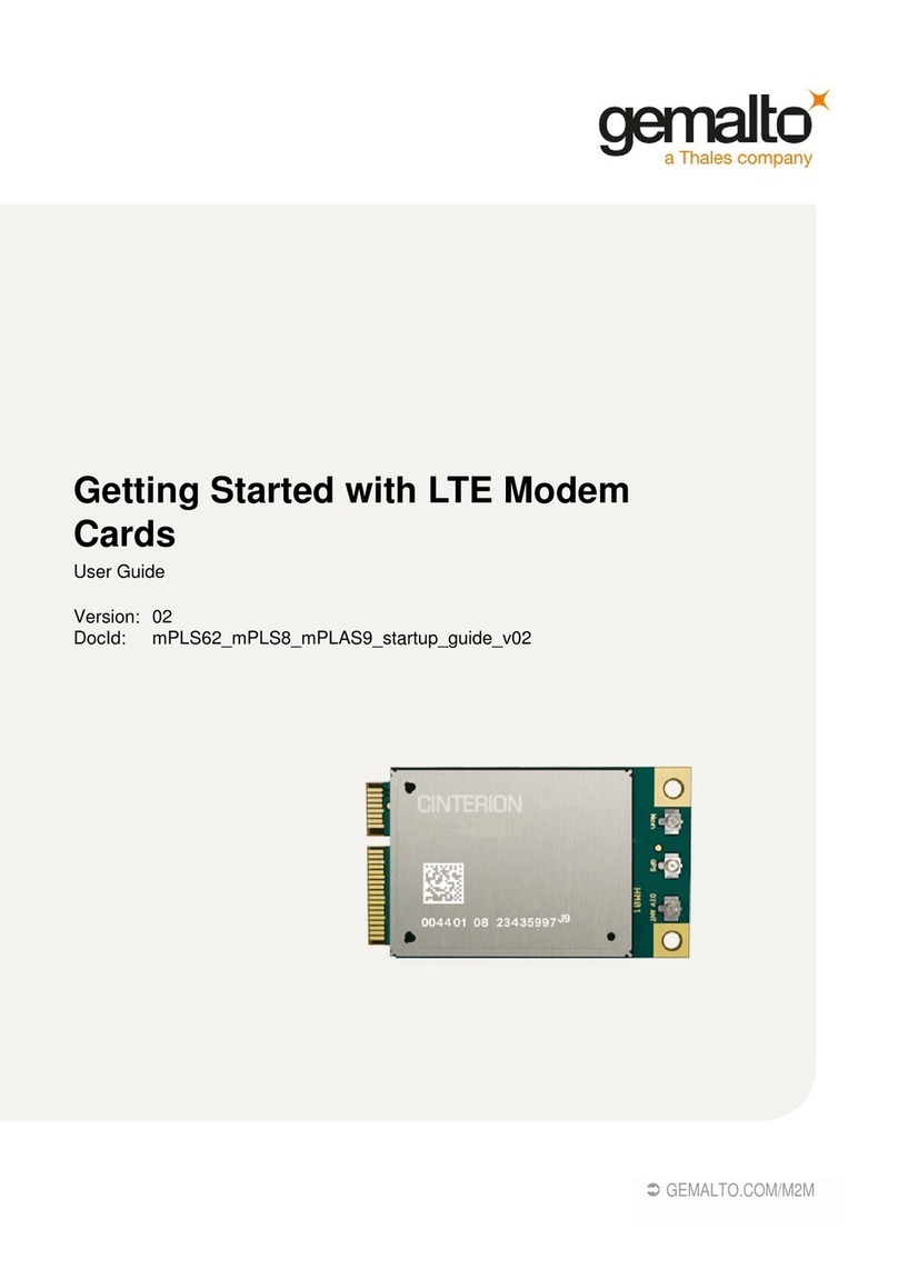
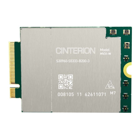
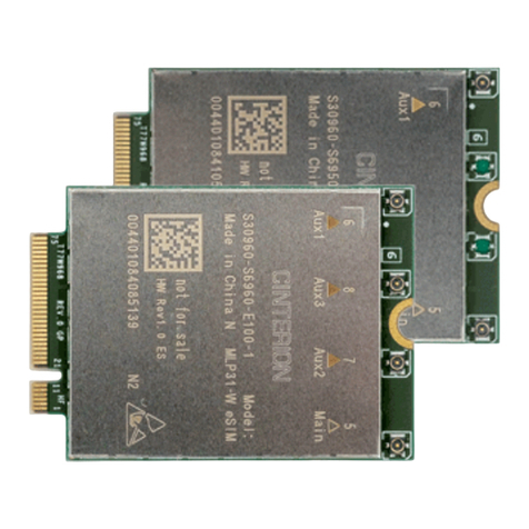
Thales mPLS62 User manual

Getting Started with LTE Modem
Cards
User Guide
Version: 03
DocId: mPLS62_mPLS8_mPLAS9_mPLSx3_ug_startup_v03

GENERAL NOTE
THIS DOCUMENT CONTAINS INFORMATION ON THALES PRODUCTS. THALES RESERVES THE
RIGHT TO MAKE CHANGES TO THE PRODUCTS DESCRIBED HEREIN. THE SPECIFICATIONS IN
THIS DOCUMENT ARE SUBJECT TO CHANGE AT THE DISCRETION OF THALES. THE PRODUCT
AND THIS DOCUMENT ARE PROVIDED ON AN "AS IS" BASIS ONLY AND MAY CONTAIN DEFICIEN-
CIES OR INADEQUACIES. THALES DOES NOT ASSUME ANY LIABILITY FOR INFORMATION PRO-
VIDED IN THE DOCUMENT OR ARISING OUT OF THE APPLICATION OR USE OF ANY PRODUCT
DESCRIBED HEREIN.
THALES GRANTS A NON-EXCLUSIVE RIGHT TO USE THE DOCUMENT. THE RECIPIENT SHALL
NOT COPY, MODIFY, DISCLOSE OR REPRODUCE THE DOCUMENT EXCEPT AS SPECIFICALLY
AUTHORIZED BY THALES.
Copyright © 2021, THALES DIS AIS Deutschland GmbH
Trademark Notice
Thales, the Thales logo, are trademarks and service marks of Thales and are registered in certain coun-
tries.
PCI-SIG®, PCIe®and the PCI Express®design mark are registered trademarks and/or service marks of
PCI-SIG.
Microsoft and Windows are either registered trademarks or trademarks of Microsoft Corporation in the
United States and/or other countries.
All other registered trademarks or trademarks mentioned in this document are property of their respective
owners.
tmPLS62_mPLS8_mPLAS9_mPLSx3_ug_startup_v03 2021-03-15
Public / Released
Getting Started with LTE Modem Cards
2
Page 2 of 21
User Guide: Getting Started with LTE Modem Cards
Version: 03
Date: 2021-03-15
DocId:
mPLS62_mPLS8_mPLAS9_mPLSx3_ug_startup_v03
Status Public / Released

Getting Started with LTE Modem Cards
Contents
21
tmPLS62_mPLS8_mPLAS9_mPLSx3_ug_startup_v03 2021-03-15
Public / Released
Page 3 of 21
Contents
0 Document History ...................................................................................................... 4
1 Introduction ................................................................................................................. 5
1.1 Supported Products ........................................................................................... 5
1.2 Related Documents ........................................................................................... 5
2 Getting Started with LTE Modem Cards ................................................................... 6
2.1 Technical Requirements for Using LTE Modem Cards...................................... 6
2.2 Connecting the LTE Modem Card to the LTE Modem Card Adapter Board...... 7
2.3 Start Up the Module ......................................................................................... 10
3 Appendix.................................................................................................................... 15
3.1 LTE Modem Card Adapter Board .................................................................... 15
3.1.1 Package content ................................................................................. 15
3.1.2 LTE Modem Card Adapter Board Description .................................... 15
3.1.3 LTE Modem Card Adapter Board Schematic...................................... 16
3.2 Digital Audio Interface (mPLSx3 only) ............................................................. 18
3.2.1 Wideband Audio Codec Adapter......................................................... 19
3.2.2 Audio Bridge ....................................................................................... 20

Getting Started with LTE Modem Cards
0 Document History
4
tmPLS62_mPLS8_mPLAS9_mPLSx3_ug_startup_v03 2021-03-15
Public / Released
Page 4 of 21
0 Document History
New document: "Getting Started with LTE Modem Cards" Version 03
Previous document: "Getting Started with LTE Modem Cards" Version 02
New document: "Getting Started with LTE Modem Cards" Version 02
Previous document: "Getting Started with LTE Modem Cards" Version 01
New document: "Getting Started with LTE Modem Cards" Version 01
Chapter What is new
-- new document layout
throughout
document
added product family PLSx3
2.2 Revised Table 2
3.2 New chapter Digital Audio Interface (mPLSx3 only)
Chapter What is new
3.1.2 Revised Figure 8
3.1.3 Revised Figure 9
Chapter What is new
--- Initial document setup.

Getting Started with LTE Modem Cards
1 Introduction
20
tmPLS62_mPLS8_mPLAS9_mPLSx3_ug_startup_v03 2021-03-15
Public / Released
Page 5 of 21
1 Introduction
This document describes a ready-to-use development and test environment for the Thales LTE
Modem Cards.
The development and test environment comprises the following hardware components
• LTE Modem Card mPLAS9-W, mPLAS9-X, mPLS8-US, mPLS8-E, mPLS62-W or mPLSx3
• LTE Modem Card Adapter Board
The purpose of this document1is to guide you through the process of connecting the hardware,
installing the supplied drivers on a Microsoft®Windows 7 or Microsoft®Windows 8 system and
getting started with LTE Modem Card.
1.1 Supported Products
This document applies to the following Thales LTE Modem cards:
•Cinterion
®mPLAS9-W
•Cinterion
®mPLAS9-X
•Cinterion
®mPLS8-US
•Cinterion
®mPLS8-E
•Cinterion
®mPLS62-W
•Cinterion
®mPLS63-W A
•Cinterion
®mPLS63-W B
•Cinterion
®mPLS83-W A
•Cinterion
®mPLS83-W B
•Cinterion
®mPLS83-X A
LTE Modem Card in this document refers to all of the above mentioned product variants. mPLSx3
is used for the 5 variants mPLS63-W A, mPLS63-W B, mPLS83-W A, mPLS83-W B and
mPLS83-X A. Where necessary a note is made to differentiate between these product variants.
1.2 Related Documents
[1] PLAS9-W AT Command Set
PLAS9-X AT Command Set
PLS8-US AT Command Set
PLS8-E AT Command Set
PLS62-W AT Command Set
PLS63-W AT Command Set
PLS83-W AT Command Set
PLS83-X AT Command Set
[2] mPLAS9-W Hardware Interface Description
mPLAS9-X Hardware Interface Description
mPLS8-US Hardware Interface Description
mPLS8-E Hardware Interface Description
mPLS62-W Hardware Interface Description
mPLSx3 Hardware Interface Description
[3] Audio Codec Adapter Setup for Cinterion®Modules
1. The document is effective only if listed in the appropriate Release Notes as part of the technical docu-
mentation delivered with your Thales product.

Getting Started with LTE Modem Cards
2 Getting Started with LTE Modem Cards
20
tmPLS62_mPLS8_mPLAS9_mPLSx3_ug_startup_v03 2021-03-15
Public / Released
Page 6 of 21
2 Getting Started with LTE Modem Cards
2.1 Technical Requirements for Using LTE Modem Cards
• LTE Modem Card (for details see Figure 1 and [2])2
• corresponding driver package (USB)
• Computer running Windows 7 or Windows 8, USB 2.0 High Speed compatible
• Local administrator privileges on the particular Windows computer to install and uninstall
the drivers
• LTE Modem Card Adapter Board (for details see Section 3.1)
• Accessories:
- Two (mPLAS9-W, mPLAS9-X, mPLS62-W) or three (mPLS8-US, mPLS8-E, mPLSx3)
short 50 Ohms RF adapter cables - 2xRF and 1xGNSS, with ultra-miniature U.FL SMT
connectors to connect the appropriate U-FL connectors on the LTE Modem Card Adapter
Board (supplied by Thales)
- Two external 50 Ohms RF antennas - GSM/UMTS/LTE main antenna and UMTS/LTE
Rx diversity/MIMO antenna, with SMA connector to connect the SMA connector on the
LTE Modem Card Adapter Board (supplied by Thales)
-mPLS8-US, mPLS8-E and mPLSx3 only: One GNSS antenna with SMA connector to
connect the SMA connector on the LTE Modem Card Adapter Board (not supplied by
Thales).
- 3.3V power supply applied at the LTE Modem Card Adapter Board for powering up the
LTE Modem Card Adapter Board and the connected LTE Modem card (not supplied by
Thales)
- USB cable with mini-USB plug (supplied by Thales)
• Appropriate application for controlling the module from within a PC’s operating system. For
Windows, e.g. Windows Hyperterminal
• (U)SIM from a GSM/UMTS/LTE network provider
2. For ordering information see [2].

Getting Started with LTE Modem Cards
2.2 Connecting the LTE Modem Card to the LTE Modem Card Adapter Board
20
tmPLS62_mPLS8_mPLAS9_mPLSx3_ug_startup_v03 2021-03-15
Public / Released
Page 7 of 21
2.2 Connecting the LTE Modem Card to the LTE Modem Card
Adapter Board
To properly connect the LTE Modem Card and all accessories to the LTE Modem Card Adapter
Board please complete the steps listed below. The complete setup with the LTE Modem Card
mounted onto the LTE Modem Card Adapter Board is shown in Figure 2.
• Ensure that all jumpers on the LTE Modem Card Adapter Board are set to their default posi-
tions as shown in Figure 8 and Table 1.
• Screw the external GSM/UMTS/LTE main and Rx diversity/MIMO antennas to the appro-
priate SMA connectors on the LTE Modem Card Adapter Board (X13 and X14).
•mPLS8-US, mPLS8-E and mPLSx3 only: Screw the external GNSS Antenna to the SMA
Connector on the LTE Modem Card Adapter Board (X15).
• Plug the USB 2.0 Mini-connector of the USB cable to the Mini USB jack at the LTE Modem
Card Adapter Board (X4). The other end of the USB cable connects to a PC.
• Insert the LTE Modem Card into the connector X1 on the LTE Modem Card Adapter Board.
• Connect the U.FL SMT connectors for the GSM/UMTS/LTE main and Rx diversity/MIMO
antennas on the LTE Modem Card Adapter Board (X10 and X11) to the matching U.FL SMT
connectors on the LTE Modem Card.
•mPLS8-US, mPLS8-E and mPLSx3 only: Connect the U.FL SMT connector for the GNSS
antenna on the LTE Modem Card Adapter Board (X12) to the matching U.FL SMT connec-
tor on the LTE Modem Card.
• Insert the (U)SIM card into the card reader labeled X8.
• If not powered over USB make sure that the power supply adapter is switched to 3V3 Volts
and place the Jumper on X20 on the LTE Modem Card Adapter Board to PIN 3 and PIN 4
(see Table 1). Connect the power cables to the red (X3 = 3V3) and black (X2 = Ground)
connectors of the LTE Modem Card Adapter Board.
After connecting the LTE Modem Card with the LTE Modem Card Adapter Board, the LTE Mo-
dem Card can be switched on. The initial startup and possible USB driver installation are de-
scribed in Section 2.3.

Getting Started with LTE Modem Cards
2.2 Connecting the LTE Modem Card to the LTE Modem Card Adapter Board
20
tmPLS62_mPLS8_mPLAS9_mPLSx3_ug_startup_v03 2021-03-15
Public / Released
Page 8 of 21
Figure 1: LTE Modem Card
Bottom side
Top side
Antenna U.FL-R SMT connectors:
Main antenna Rx Diversity/MIMO antenna
Cinterion®SMT module
GPS antenna1)
PCI Express® Mini Card system connector
PIN 1 PIN 51 PIN 2 PIN 52
1) GPS Antenna only supported by mPLS8-E, mPLS8-US and mPLSx3 LTE Modem Cards

Getting Started with LTE Modem Cards
2.3 Start Up the Module
20
tmPLS62_mPLS8_mPLAS9_mPLSx3_ug_startup_v03 2021-03-15
Public / Released
Page 10 of 21
2.3 Start Up the Module
After connecting the LTE Modem Card to the LTE Modem Card Adapter Board as described in
Section 2.2, the module can be switched on.
Note: The USB drivers provided by Thales need to be available. Copy the supplied driver files
to a folder on the Windows computer. Be sure to use the latest USB driver software supplied
by Thales.
• Start the Windows PC.
• switch on the external 3.3V power supply, when the power supply of the LTE Modem Card
Adapter Board will be not done via USB.
• If the USB cable was plugged as described above, and the USB drivers provided by Thales
were not yet installed on the computer, you will be prompted to install them:
- On Windows 7 or Windows 8, wait a few seconds until all USB devices show up as "CDC
Serial" in the Windows Device Manager under "Other Devices". Then - from top to bottom
- right-click each "CDC Serial" device, select the option "Update Driver Software...",
browse to the folder you copied the Thales USB drivers to, and select this folder to update
the driver software from.
For mPLS62-W and mPLSx3 there will “PLSx” devices shown, which have to be
updated. Then - from top to bottom - right-click each PLSx” device, select the option
"Update Driver Software...", browse to the folder you copied the Thales USB drivers to,
and select this folder to update the driver software from.
- In any case, cancel any Windows instructions to update the software automatically. For
each USB device take care to browse to the folder containing the unzipped driver soft-
ware.
After successful USB driver installation the installed USB devices are listed in the Windows
Device Manager under "Modems", "Network adapters" and "Ports (COM & LPT)" as shown
in Figure 3 for mPLS8-E/US, in Figure 4 for mPLAS9-W/X, in Figure 5 for mPLS62-W and
in Figure 6 for mPLSx3.
Figure 3: Installed USB devices mPLS8-E/US

Getting Started with LTE Modem Cards
2.3 Start Up the Module
20
tmPLS62_mPLS8_mPLAS9_mPLSx3_ug_startup_v03 2021-03-15
Public / Released
Page 11 of 21
mPLS8-E/US:
The assignment of the module’s installed USB CDC ACM ports 1-4 (see Figure 3), the ASC0
UART interface and the possible Multiplex channels to the two AT command service instances
MDM and APP as well as the NMEA streaming service interfaces is done by the AT command
AT^SSRVSET. The command provides a number of pre-configured service sets and a custom-
izable service set.
With PLS8 for example, Service Set 1 is configured as delivery default:
• the MDM service is available at the ASC0 interface (UART COM port)
• the APP service is available at the USB interface (CDC ACM port 1)
• the NMEA service (reserved for GNSS data) is also available at the USB interface (CDC
ACM port 2)
The AT command AT^SQPORT shows whether the MDM or APP service is connected to the
device interface the command was sent over.
The two USB devices implemented as USB CDC ECM network adapters are activated and de-
activated by the AT command AT^SWWAN. Via the two WWAN or RmNet adapters different
APNs can be assigned and used simultaneously.
For further details and more information on the above AT commands to configure and operate
the module please refer to [1].
Figure 4: Installed USB devices mPLAS9-W/X
PLAS9-W/X:
The assignment of the module’s installed LTE USB Modem and LTE USB ports 1-4 (see Figure
4) to the two AT command service instances MDM and APP is done by the AT command
AT^SSRVSET. The command provides a number of preconfigured service sets and a custom-
izable service set.

Getting Started with LTE Modem Cards
2.3 Start Up the Module
20
tmPLS62_mPLS8_mPLAS9_mPLSx3_ug_startup_v03 2021-03-15
Public / Released
Page 12 of 21
With PLAS9-W for example, Service Set 2 is configured as delivery default:
• the MDM service is available at the USB0 interface (CDC ACM LTE USB Modem port)
• the APP service is available at the USB1 interface (CDC ACM LTE USB serial port 1)
The AT command AT^SQPORT shows whether the MDM or APP service is connected to the
device interface the command was sent over.
The two USB devices implemented as USB CDC ECM wireless network adapters are activated
and deactivated by the AT command AT^SWWAN. Via the two WWAN or RmNet adapters dif-
ferent APNs can be assigned and used simultaneously.
For further details and more information on the above AT commands to configure and operate
the module please refer to [1].
Figure 5: Installed USB devices mPLS62-W
mPLS62-W:
The two USB devices implemented as USB CDC ECM network adapters are activated and de-
activated by the AT command AT^SWWAN. Via the two WWAN or RmNet adapters different
APNs can be assigned and used simultaneously.
With the AT command AT^SSRVSET the two USB CDC ECM network adapters can be
changed to one USB CDC MBIM (Mobile Broadband Interface Model) interface.
For further details and more information on the above AT commands to configure and operate
the module please refer to [1].

Getting Started with LTE Modem Cards
2.3 Start Up the Module
20
tmPLS62_mPLS8_mPLAS9_mPLSx3_ug_startup_v03 2021-03-15
Public / Released
Page 13 of 21
Figure 6: Installed USB devices mPLSx3
mPLSx3:
The USB device "Cinterion M2M HS-USB WWAN Adapter" is activated and deactivated by the
AT command AT^SWWAN.
With the AT command AT^SSRVSET the WWAN network adapter can be changed to one USB
CDC ECM (Ethernet Connection Model) interface, but there is no driver support for Windows.
For further details and more information on the above AT commands to configure and operate
the module please refer to [1].

Getting Started with LTE Modem Cards
2.3 Start Up the Module
20
tmPLS62_mPLS8_mPLAS9_mPLSx3_ug_startup_v03 2021-03-15
Public / Released
Page 14 of 21
• For example, to connect to the mPLS9-W LTE Modem Card via USB interface, check the
properties of the enumerated CDC ACM LTE USB serial port 1, call a terminal program on
the PC and connect to the assigned COM port - in the below Figure 7 to COM port 47
assigned to the CDC ACM LTE USB serial port 1 (Figure 4). You may have to type the AT
command ATE1 to enable an echo for entered AT commands and then type ATI to display
module identification information.
Figure 7: Connection via ALSx PLSx LTE USB serial port

Getting Started with LTE Modem Cards
3 Appendix
20
tmPLS62_mPLS8_mPLAS9_mPLSx3_ug_startup_v03 2021-03-15
Public / Released
Page 15 of 21
3 Appendix
3.1 LTE Modem Card Adapter Board
3.1.1 Package content
The LTE Modem Card Adapter Board will be delivered together with
• 1 USB Cable (USB Connector A to USB Mini Connector B)
• 3 Hirose Antenna cables
• 2 GMS/UMTS/LTE Antennas
GNSS Antenna and Power supply are not part of the LTE Modem Card Adapter Board delivery.
Ordering Number: L30960-N3202-A300
3.1.2 LTE Modem Card Adapter Board Description
The LTE Modem Card Adapter Board can be powered over USB (X20: Jumper 1-2) or by an
external power supply connected to X2 (GND) and X3 (3V3). For the usage of the external pow-
er supply the jumper on X20 must be set on PIN 3 and Pin 4. On X20 all other signals used by
the LTE Modem Card except USB signals are available.
Table 1: Signals and Jumper on X20
Signal X20 Signal
VDD_3V3 12USB_3V3
VDD_3V3 3 4 EXT_3V3
GND 5 6 GND
1V8 7 8 ANT_CTRL0
LED_WWAN# 9 10 ANT_CTRL1
WAKE# 11 12 LED_WLAN#
PERST#13 14GND
W_DISABLE# 15 16 LED_WPAN#
GND 17 18 PCM_CLK
GND 19 20 PCM_OUT
SMB_CLK 21 22 PCM_IN
SMB_DATA 23 24 PCM_FSC

Getting Started with LTE Modem Cards
3.1 LTE Modem Card Adapter Board
20
tmPLS62_mPLS8_mPLAS9_mPLSx3_ug_startup_v03 2021-03-15
Public / Released
Page 16 of 21
Figure 8: LTE Modem Card Adapter Board Jumper and Connectors
3.1.3 LTE Modem Card Adapter Board Schematic
The schematic of the LTE Modem Card Adapter Board is shown in Figure 9.
Antenna connectors
Main Diversity GNSS
Power Supply
GND +3.3V
1st SIM
Interface
USB
2nd SIM
Interface
PWR OK
LED
PCI Express®Mini Card system connector
for LTE Modem Card Reset
Switch
PWR_ON
LED

Getting Started with LTE Modem Cards
3.2 Digital Audio Interface (mPLSx3 only)
20
tmPLS62_mPLS8_mPLAS9_mPLSx3_ug_startup_v03 2021-03-15
Public / Released
Page 18 of 21
3.2 Digital Audio Interface (mPLSx3 only)
The mPLSx3 product family supports a digital audio interface, which can be used together with
the LTE Modem Card Adapter Board. Therefore following parts are needed:
- Wideband Audio Codec Adapter (ordering number: L30960-N0120-A100)
- Audio Brigde (delivered with the Wideband Audio Codec Adapter)
Remove the Jumper from X20 and connect the Audio Brigde on X20 of LTE Modem Card
Adapter Board. Place the Jumper on the Audio Bridge at the same location as previous on
X20.Then connect the Wideband Audio Codec Adapter on the Audio Brigde. For more stability
use a spacer and 2 screws between the single screw hole on the Wideband Audio Codec
Adapter and the corresponding hole of the LTE Modem Card Adapter Board. Figure 10 shows
the set-up,.
Figure 10: LTE Modem Card Adapter Board with Audio Brigde and Wideband Audio Codec Adapter
LTEModemAdapterBoard
WidebandAudioCodecAdpater
AudioBrigde
Headphone
Speaker
Right Microphone
Left Microphone
Headset (RJ9)
place here a spacer between Wideband Audio Codec Adapter
and LTE Modem Card Adapter
Jumper

Getting Started with LTE Modem Cards
3.2 Digital Audio Interface (mPLSx3 only)
20
tmPLS62_mPLS8_mPLAS9_mPLSx3_ug_startup_v03 2021-03-15
Public / Released
Page 19 of 21
3.2.1 Wideband Audio Codec Adapter
For using the Wideband Audio Codec Adapter together with LTE Modem Card, the Wideband
Audio Codec Adapter must be configured by switches (see Figure 11 and Table 2) and the
PCM or I2S Interface must be enabled by AT command AT^SAIC on the LTE Modem Card (see
Table 2 and [1]).
Figure 11: DIP Switches on Wideband Audio Codec Adapter
Legend:
1: Switch set to up position
0: Switch set to the down position
"LEDs": The colors , , and indicate the color of the LEDs that light up at the Wideband Audio Codec Adapter.
The Wideband Audio Codec Adapter +5V0 and +2V9 power supply pins are connected to 3.3V
with the following limitations:
- +2V9 powers all ICs. They all are 3.3V capable. LEDs may light a little bit brighter.
- The codec's sensitivity may decrease by around 1dB.
- +5V0 feeds the handset microphone. If the Votronic handset is used with 3.3V instead of
5V feeding, its microphone sensitivity may be decreased by up to 3dB. Other handsets
or accessory may not be affected.
- +5V0 also supplies the speaker driver in the codec. With 3.3V the reference voltage is
not centered any more within 5V and positive signals may be clipped earlier than the neg-
ative signals.The corresponding codec register may be set for 3.3V operation via serial
interface to correct this behavior (Register 49, bit2 = 0).
For more details about the Wideband Audio Codec Adapter, refer to [3].
Table 2: DIP switch and AT command settings
Product AT^SAIC setting Wideband Audio Codec Adapter DIP switch settings
Up
Ext. Ext. TC65i
(1.8V)
WB/
16kHz
LONGFS
I2SMaster
Down
Int.
I2C
Int.
MCLK
NORM
(3V)
NB/
8kHz
SHORTFS
PCM Slave
mPLSx3 AT^SAIC=4,1,1,3,0,0,1,1 0 0 1 1 0 0 0
AT^SAIC=4,1,1,3,0,0,1,0 0 0 1 0 0 0 0
AT^SAIC=5,1,1,1,0,0,1,1 0 0 1 1 0 1 0
AT^SAIC=5,1,1,1,0,0,1,0 0 0 1 0 0 1 0
up
down

Getting Started with LTE Modem Cards
3.2 Digital Audio Interface (mPLSx3 only)
20
tmPLS62_mPLS8_mPLAS9_mPLSx3_ug_startup_v03 2021-03-15
Public / Released
Page 20 of 21
3.2.2 Audio Bridge
The Audio Bridge connects the LTE Modem Card Adapter Board with the Wideband Audio Co-
dec Adapter. Figure 12 shows the size and Figure 13 the schematic of the Audio Brigde.
Figure 12: Size of the Audio Bridge
Figure 13: Schematic of the Audio Brigde
30mm
35mm
1
1
2
2
X100
X101
12
9
10
7
5
3
4
6
8
12
34
56
78
910
11 12
13 14
15 16
17 18
19 20
21 22
23 24
VDD_3V3
PCM_FSC
PCM_IN
PCM_OUT
PCM_CLK
This manual suits for next models
3
Table of contents
Other Thales Network Card manuals
Popular Network Card manuals by other brands
Accton Technology
Accton Technology Cheetah EtherCard-2320 Quick installation guide
ADTRAN
ADTRAN TSU 600 user manual
National Instruments
National Instruments Network Adapter NI PXIe-6672 user manual
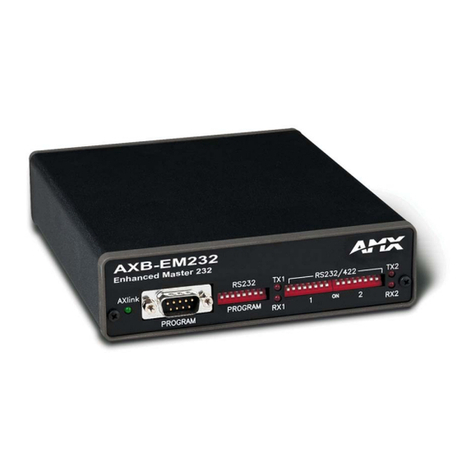
AMX
AMX AXB-EM232 instruction manual
TRENDnet
TRENDnet TE100-PCBUSR - DATA SHEETS user guide
HP
HP PN1050 Quick setup guide


