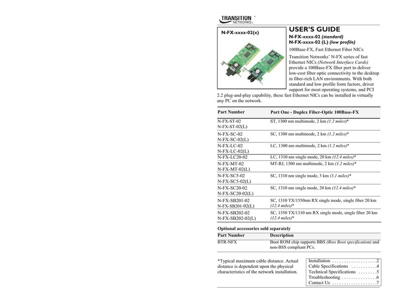
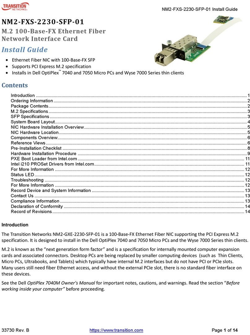
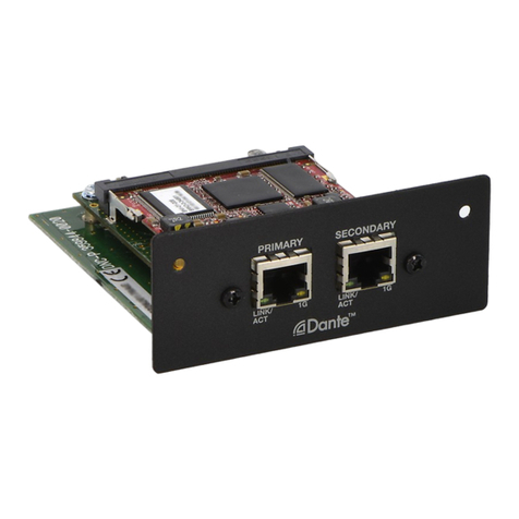
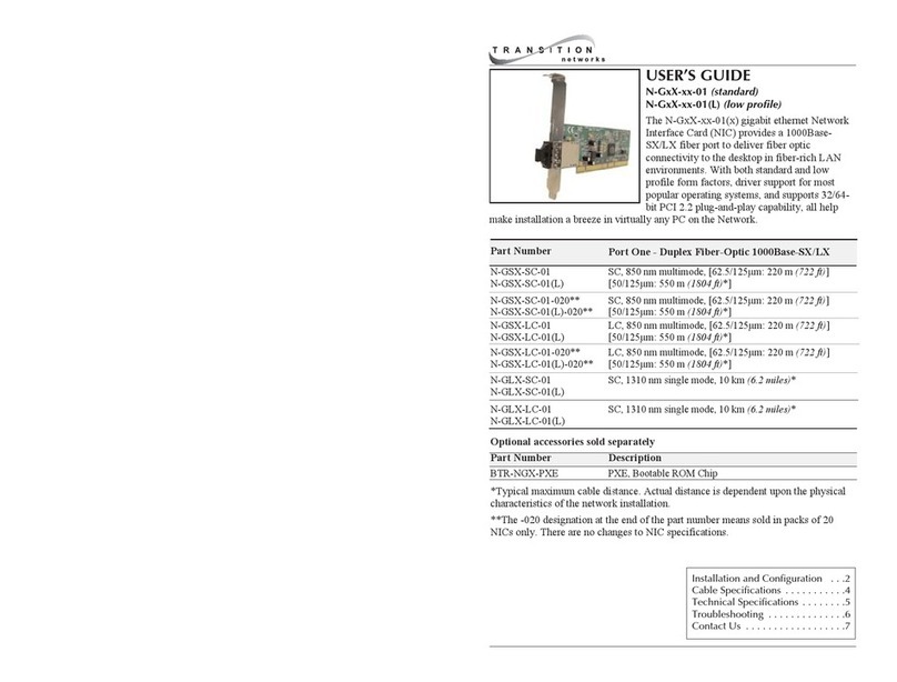
Transition Networks NM2-FXS-2230-SFP-01 User manual

NM2-FXS-2230-SFP-01 Install Guide
33730 Rev. C https://www.transition.com Page 1 of 14
NM2-FXS-2230-SFP-01
M.2 100-Base-FX Ethernet Fiber
Network Interface Card
Install Guide
•Ethernet Fiber NIC with 100-Base-FX SFP
•Supports PCI Express M.2 specification
•Installs in Dell OptiPlex™ 7040 and 7050 Micro PCs and Wyse 7000 Series thin clients
Contents
Introduction ......................................................................................................................................................................1
Ordering Information ........................................................................................................................................................2
Features ...........................................................................................................................................................................2
Package Contents............................................................................................................................................................2
M.2 Specifications............................................................................................................................................................3
SFP Specifications...........................................................................................................................................................3
System Board Layout.......................................................................................................................................................4
NIC Hardware Installation Overview ................................................................................................................................5
NIC Hardware Location....................................................................................................................................................5
Components Overview.....................................................................................................................................................6
Reference Views ..............................................................................................................................................................6
Pre-Installation Checklist .................................................................................................................................................8
Hardware Installation Procedure .....................................................................................................................................9
PXE Boot Loader from Intel.com ...................................................................................................................................11
Intel i210 PROSet Drivers from Intel.com ...................................................................................................................... 11
For More Information .....................................................................................................................................................12
Status LED .....................................................................................................................................................................12
Troubleshooting .............................................................................................................................................................12
For More Information .....................................................................................................................................................12
Record Device and System Information ........................................................................................................................13
Contact Us .....................................................................................................................................................................13
Compliance Information .................................................................................................................................................13
Declaration of Conformity ..............................................................................................................................................14
Record of Revisions.......................................................................................................................................................14
Introduction
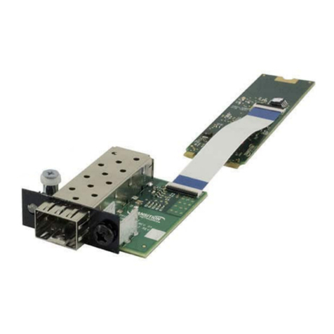
The Transition Networks NM2-FXS-2230-SFP-01 is a 100-Base-FX Ethernet Fiber NIC supporting the PCI Express M.2
specification. It is designed to install in the Dell OptiPlex 7040 and 7050 Micro PCs and the Wyse 7000 Series thin clients.
M.2 is known as the “next generation form factor” and is a specification for internally mounted computer expansion
cards and associated connectors. Desktop PCs are being replaced by smaller computing devices (such as Thin Clients,
Micro PCs, Ultrabooks, and Tablets) which typically have internal M.2 interfaces but do not have PCI or PCIe slots.
Many users still need fiber Ethernet access, and without the external PCIe slot, there is no standard fiber interface on
these devices.
See the Dell
OptiPlex 7040M Owner's Manual
for important notes, cautions, and warnings. Read the section “
Before
working inside your computer”
before proceeding.
NM2-FXS-2230-SFP-01 Install Guide
33730 Rev. C https://www.transition.com Page 2 of 14
Ordering Information
SKU
Description
NM2-FXS-2230-SFP-01
100-Base-FX Ethernet Fiber NIC with 100-Base-FX to SGMII SFP
Transition Networks M.2 100-Base-FX Ethernet Fiber Network Interface Card (NIC) provides a fiber optic interface for the
Dell OptiPlex™ 7040 and 7050 Micro PCs and the Wyse 7000 Series thin clients. The NM2-FXS-2230-SFP-01 consist of a
M.2 NIC that installs into the OptiPlex Micro PC’s M.2 “A or E keyed” interface, a fiber optic adapter that installs into the
OptiPlex Micro PC’s Option port, a 20-pin Flat Flex Cable (FFC) with right-angle bend connecting the NIC to the fiber
adapter, and a 100-Base-FX to SGMII SFP module.
Features
•PCI Express M.2 compliant
•Flow Control
•A + E keyed M.2 interface
•Wake on LAN (WOL)
•Full duplex
•Smart Load Balancing (SLB)
•IPv6 capable
•TCP Segmentation Offload (TSO)
•Supports UEFI
•Message Signaled Interrupts (MSI)
•Supports PXE boot
•Extended Message-Signaled Interrupts (MSI-X)
•Jumbo frame support 9014 bytes
•LACP support (Teaming)
•100Base-FX to SGMII SFP interface
Package Contents
Verify that you have received the following items. Contact your sales representative if any item is missing. Please save
the packaging for possible future use.
One Media Converter in anti-static pouch.
One TN-SFP-GE-100FX SFP in anti-static pouch.
One M.2 NIC PCB attached to FFC Cable in anti-static pouch.
Parts in a 4x6 baggie (1 each): #4 Flat Head Screw, #4 Nylon Washer, #6 Black SEMS Screw.
One Documentation Postcard.

NM2-FXS-2230-SFP-01 Install Guide
33730 Rev. C https://www.transition.com Page 3 of 14
Note that this NM2-FXS-2230-SFP-01 SFP transceiver is sold separately and also as a part of Transition Networks’ NM2-
FXS-2230-SFP-01 M.2 100-Base-FX Ethernet Fiber NIC. See the applicable SFP manual for more information on the SFP
bundled with the M.2 NIC.
M.2 Specifications
M.2 module naming per specification: 2230-D4-A-E. Key IDs: A and E. Jumbo frame support: 9014 bytes. PXE boot loader
image pre-loaded. Uses standard i210 PROSet drivers from Intel. Operating system support: Windows 10 32/64-bit;
Windows 8 and 8.1 32/64-bit; Windows 7 32/64-bit; Linux.
Standards IEEE 802.3-2012
Bus Slot M.2 - 2230-D4-A-E, Key IDs: A and E.
Data Rate 100 Mbps (FDX only).
Max Frame Size 9014 bytes
Status LED MC LED 1: Link/Activity LED. LINK/ACT (Amber ON = Link; Flashing = Activity).
Color is amber when 100M.
Dimensions:
M.2 NIC: Width: 0.87” [22 mm] x Depth: 1.19" [30 mm] x Height: 0.12” [3.08 mm].
Fiber Optic Adapter: Width: 1.65” [42 mm] x Depth: 2.05” [52 mm] x Height: 0.51” [13 mm].
FFC Cable: Length: 6” [15.3 cm] without right-angle bend; 5.5” [14 cm] with right-angle bend.
Power Consumption NM2-FXS-2230-SFP-01: 120 mA at 3.3V (0.4 W typical) (not including SFP).
Power Consumption SFP: 330mA at 3.3V, 1W typical.
Power Source M.2 interface connector; 3.3V (refer to Table 41 of M.2 specification).
Operating Temp. 0°C to +45°C (+32°F to +113°F).
Storage Temp. -40°C to +85°C
Humidity 5% to 95% (non-condensing).
Altitude 0 – 10,000 ft.
Weight 0.1 lbs. [0.05 kg]
Compliance CE Mark; Emissions: EN55032, FCC Part 15; Class A; Immunity: EN55024.
Data Speed: SFP optic at 100Mbs, full duplex only.
Fiber Port (-SFP): 100Base-X open SFP slot.
DIP Switches / Jumpers: None
Warranty Lifetime
SFP Specifications
The TN-SFP-GE-100FX is a Small Form Factor Pluggable (SFP) transceiver compatible with the Multi-Sourcing Agreement
(MSA), designed for SGMII MAC interface to 100BASE-FX. The SGMII MAC Interface uses modified 1000BASE-X Auto-
Negotiation to indicate link, duplex, and speed to the MAC. It data links up to 2km with 50/125um multi mode fiber.
Features include:
•Data Rate (Mbps): 125
•Media: MMF
•Wavelength (nm): 1310
•Transmission Distance(km): 2
•DDMI: Yes

NM2-FXS-2230-SFP-01 Install Guide
33730 Rev. C https://www.transition.com Page 4 of 14
TN-SFP-GE-100FX transceivers support the 2-wire serial communication protocol per the SFP MSA. It is closely related to
the E2PROM defined in the GBIC standard, with the same electrical specifications. The standard SFP serial ID provides
identification information describing the transceiver’s capabilities, standard interfaces, manufacturer, and other
information. The TN-SFP-GE-100FX also provides a Digital Diagnostic Monitoring Interface that allows real-time access to
device operating parameters. See the full SFP manual for more details.
System Board Layout
The OptiPlex 7040 Micro has two M.2 expansion slots: one 22x30 slot (#10 in below diagram)
and one 22x80 slot (#13 in below diagram). The NM2-FXS-2230-SFP-01 installs in the 22x30 slot
(#10 in below diagram). See the
Dell OptiPlex 7040M Owner's Manual
for more details.
1. Processor
11. Power switch
2. CPU fan connector
12. Hard drive connector
3. Internal speaker connector
13. M.2 socket3 connector
4. Memory module connectors
14. Coin cell battery
5. USB 3.0 connector
15. RJ-45 Ethernet connector
6. Intrusion switch
16. USB 3.0 connector
7. USB 3.0 connector
17. DP/VGA daughter board connector
8. Line out connector
18. DisplayPort connector
9. Universal audio jack
19. HDMI connector
10. M.2 socket1 connector
20. DC-in jack

NM2-FXS-2230-SFP-01 Install Guide
33730 Rev. C https://www.transition.com Page 7 of 14
CAUTION: Only qualified persons should install the NIC. Failure to observe this caution could result in poor performance
or damage to the equipment. Before installing the NIC, review the Pre-Installation Checklist and Safety Precautions
below.
CAUTION: Wear a grounding device and observe electrostatic discharge precautions when installing the NIC in a system.
Failure to observe this caution could result in damage to the NIC. Before installing the NIC, review the Pre-Installation
Checklist and Safety Precautions below. Before installing the NIC, ensure that system power is OFF, the power cord is
unplugged from the power outlet, and that proper electrical grounding procedure has been followed.
WARNING: High voltage inside the system may present a safety hazard. Make sure that the system power is off before
removing the cover. Unplug and disconnect the PC and then wait for 15-20 seconds before plugging the NIC into the PC.
When removing the NIC, unplug the Ethernet cable before removing the PC cover.

NM2-FXS-2230-SFP-01 Install Guide
33730 Rev. C https://www.transition.com Page 8 of 14
Pre-Installation Checklist
Before installing your NIC, review the preceding sections, and then do the following:
1. Verify that your system is using the latest BIOS.
2. If you download the driver software, record the path where you saved the downloads.
3. If your system is active, shut it down. Do not install the NIC until system power is completely removed. When system
shutdown is complete, power OFF and unplug your system.
4. Holding the NIC by the edges, remove it from its shipping package and place it on an antistatic surface.
5. Check the NIC for signs of damage, particularly on the PCB edge connector. CAUTION: Never attempt to install a
damaged NIC card. If the NIC is damaged, report it to Transition Networks.
6. CAUTION: Wear a grounding device and observe electrostatic discharge precautions when installing the NIC in a
system. Failure to observe this caution could result in damage to the NIC. Before installing the NIC, ensure that system
power is OFF, the power cord is unplugged from the power outlet, and that proper electrical grounding procedures have
been followed.
7. CAUTION: Install the NIC in an operating environment where the temperature range is from 0°C to +45°C (+32°F to
+113 °F), with relative humidity of 5% to 90% non-condensing. Failure to observe this caution could result in poor
equipment performance.
8. CAUTION: DO NOT install the NIC in areas where strong electromagnetic fields (EMF) exist. Failure to observe this
caution could result in poor equipment performance and data corruption.
NM2-FXS-2230-SFP-01
9. Note: You must install the TN-SFP-GE-100FX in the open SFP slot before you power up the PC.
10. Class I Laser Compliance: This product has been tested and found to comply with the limits for FDA Class I laser for
IEC60825, EN60825, and 21CFR1040 specifications. Warning: Visible and invisible laser radiation when open. DO NOT
stare into laser beam or view directly with optical instruments. Failure to observe this warning could result in damage to
your eyes or blindness.

NM2-FXS-2230-SFP-01 Install Guide
33730 Rev. C https://www.transition.com Page 9 of 14
Hardware Installation Procedure
1. Remove PC cover.
2. Gently remove the HDD Assembly. See the Dell or Wyse documentation.
3. Remove the 15-Pin DSUB knockout.
4. Install the M.2 NIC Assembly into Motherboard M.2 Edge Connector.
5. Secure the M.2 NIC Assembly into place using the Securing Screw
6. Install the Fiber Optic Adapter into the VGA opening in PC Case, as shown below.
7. Attach to PC Case using Black SEMS Screw #6-32x1/4”, and partially tighten to hold in place as shown below.
8. Align #4 Standoff with Top Hole in PC Case.
9. Slip #4 Nylon Washer on top of #4 Standoff and insert #4 Screw to secure.
10. Tighten using Black SEMS Screw #6-32x1/4”.

NM2-FXS-2230-SFP-01 Install Guide
33730 Rev. C https://www.transition.com Page 10 of 14
11. Lift Locking Lever of FFC Connector on fiber optic adapter.
12. Insert end of 20-Position FFC Cable into fiber optic adapter, with Pins facing down.
13. Push Locking Lever Down to Lock. Check that Cable is secure. See figure below for final placement.
14. Gently replace the HDD Assembly.
15. Replace PC cover.
16. Install the TN-SFP-GE-100FX in the open SFP slot, and then power up the PC.
Final Placement

NM2-FXS-2230-SFP-01 Install Guide
33730 Rev. C https://www.transition.com Page 11 of 14
PXE Boot Loader from Intel.com
PXE boot loader image pre-loaded: https://downloadcenter.intel.com/download/19186/Intel-Ethernet-Connections-
Boot-Utility-Preboot-Images-and-EFI-Drivers.
Intel i210 PROSet Drivers from Intel.com
If your PC does not automatically detect the NM2-FXS-2230-xx-01 NIC, download and install the standard i210 PROSet
drivers from Intel at http://www.intel.com/content/www/us/en/support/network-and-i-o/ethernet-
products/000005686.html.
The Intel® PROSet for Windows* Device Manager is an extension for Windows Device Manager. When you install
the Intel PROSet software, tabs are automatically added to the supported Intel adapters in Windows Device Manager.
These features allow you to test and configure wired Intel® Ethernet Adapters.
The links below apply to the NM2-FXS-2230-SFP-01. At each link, there is a 32-bit and a 64-bit download for each OS.
Intel® Network Adapter Driver for Windows* 7.
Intel® Network Adapter Driver for Windows* 8.1.
Intel® Network Adapter Driver for Windows® 10.
The full set of Intel Network Adapter Drivers for download (e.g., for Linux, Windows Server, etc.) is available.
Transition Networks Resources page has Drivers (ZIP format) for Windows 10 32bit Driver, Windows 10 64bit Driver,
Windows 7 32bit Driver, Windows 7 64bit Driver, Windows 8 32bit Driver, and Windows 8 64bit Driver.

NM2-FXS-2230-SFP-01 Install Guide
33730 Rev. C https://www.transition.com Page 12 of 14
For More Information
To view the Dell™ OptiPlex™ User’s Guide at the Support Center web page:
1. Click Start → Help and Support →Dell User and System Guides → System Guides.
2. Click the User’s Guide for your computer.
The User’s Guide is also available on the optional Drivers and Utilities media.
Support for Wyse 7020 Thin Client is on the Dell Wyse support page.
Status LED
The Media Converter has a status LED for checking Link/Activity.
MC LED 1: Link/Activity LED On = Link; Flashing = Activity. Color is amber when 100M.
Troubleshooting
This section lists some common problems, their causes, and potential recovery steps.
1. Confirm the Pre-Installation Checklist items on page 8.
2. Verify the Hardware Installation Procedure on page 9.
3. Check that the cabling is securely attached. See the FOA troubleshooting guide or the SFP manual.
4. Check for a mismatch of speed, duplex, protocol, or cable type.
5. Make sure the TN-SFP-GE-100FX is plugged in to the open SFP slot before you power on the PC. Failure to do so will
cause the device to fail, in which case you must shut down and restart the PC.
6. Use the troubleshooting procedures in the
Dell™ OptiPlex™ User’s Guide
.
7. Use the troubleshooting procedures on the PXE Boot Loader webpage as required.
8. Use the troubleshooting procedures on the Intel i210 PROSet Drivers webpage as required.
9. Verify that the link partner is active and can send/receive traffic; make sure partner settings match; verify that the
port is enabled; try connecting to another port or link partner. Check for incompatible or conflicting devices / settings.
10. Run Windows Device Manager and scan for changes.
11. Check if the PC’s BIOS version is appropriate and update to the latest. See the PC documentation.
12. Run the PC diagnostics (e.g., Dell Quick Test or Dell pre-boot diagnostics).
13. Automatically detect and update drivers and software if you are connected to the Internet from the computer that
needs updated drivers from http://www.intel.com/support/network/sb/CS-031482.htm.
14.Record information and contact TN Technical Support. See Recording Model and System Information below.
For More Information
Technical information in this document is subject to change without notice. See our SFP Products for more information.
The Fiber Optic Association, Inc. provides a Technical Bulletin on “Guidelines For Testing And Troubleshooting Fiber
Optic Installations” at http://www.thefoa.org/tech/guides/TT3.pdf Other FOA Technical Bulletins to be used as
references for the design and planning of the network can be downloaded from the FOA Tech Topics website.

NM2-FXS-2230-SFP-01 Install Guide
33730 Rev. C https://www.transition.com Page 13 of 14
Record Device and System Information
After performing the troubleshooting steps, and before calling or emailing Technical Support, please record as much
information as possible in order to help the TN Tech Support Specialist. Record the following information:
1. Product ID: ___________________________ MAC Address: ____________________________________________
Serial #: _______________________________ Board Rev: _______________________________________________
LED status: ______________________________________________________________________________________
2. Record the System information: Check your computer documentation for support information.
PC make and model: ______________________________________________________________________________
Operating System: ________________________________________________________________________________
BIOS version: ____________________________________________________________________________________
Intel i210 Driver version: ___________________________________________________________________________
PC’s Icon Tray indication: __________________________________________________________________________
Connected Device(s): _____________________________________________________________________________
3. Provide your TN service contract number: ____________________________________________________________
4. Describe the failure: _____________________________________________________________________________
_______________________________________________________________________________________________
_______________________________________________________________________________________________
5. Describe any action(s) already taken to resolve the problem: ____________________________________________
_______________________________________________________________________________________________
Contact Us
Technical Support: Technical support is available 24-hours a day
US and Canada: 1-800-260-1312
International: 00-1-952-941-7600
Main Office
tel: +1.952.941.7600 | toll free: 1.800.526.9267 | fax: 952.941.2322
Address
Transition Networks
10900 Red Circle Drive
Minnetonka, MN 55343, U.S.A.
Web: https://www.transition.com
Compliance Information
EN 55024: 2010. EN 55032: 2012/AC: 2013. AS/NZS CISPR 32: 2013. VCCI V-3/2015.04. ICES-003, Issue 6: 2016
FCC Part 15 Subpart B.

NM2-FXS-2230-SFP-01 Install Guide
33730 Rev. C https://www.transition.com Page 14 of 14
Declaration of Conformity
Modification of NIC voids regulatory agency compliance. See packaging for DoC, FCC, Canadian, and European
regulations and warnings, and other regulatory agency information.
High Risk Activities Disclaimer: Components, units, or third-party products used in the product described herein are NOT
fault-tolerant and are NOT designed, manufactured, or intended for use as on-line control equipment in the following
hazardous environments requiring fail-safe controls: the operation of Nuclear Facilities, Aircraft Navigation or Aircraft
Communication Systems, Air Traffic Control, Life Support, or Weapons Systems ("High Risk Activities"). Transition
Networks and its supplier(s) specifically disclaim any expressed or implied warranty of fitness for such High Risk
Activities.
Record of Revisions
Rev
Date
Notes
A
6/2/17
Initial release for production.
B
12/8/17
Update driver information.
C
9/1/20
Update features.
Trademark notice: All trademarks and registered trademarks are the property of their respective owners.
Copyright restrictions: © 2017-2020 Transition Networks. All rights reserved. No part of this work may be reproduced
or used in any form or by any means - graphic, electronic or mechanical - without written permission from Transition
Networks.
This manual suits for next models
1
Table of contents
Other Transition Networks Network Card manuals

Transition Networks
Transition Networks N-FX-MT-01 User manual

Transition Networks
Transition Networks M2-FXS-2230-SFP-01 User manual

Transition Networks
Transition Networks N-GXX-XX-01 User manual

Transition Networks
Transition Networks N-FX-xx-03 User manual

Transition Networks
Transition Networks N-GXE-POE-x-01 Series User manual

Transition Networks
Transition Networks N-FX-xxxx-02 User manual

Transition Networks
Transition Networks NDM-FTX-XX-01 User manual

Transition Networks
Transition Networks N-GXE Series User manual

Transition Networks
Transition Networks LANart EFA0201 User manual

Transition Networks
Transition Networks N-FXE-xxx-01 User manual