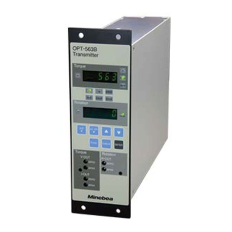
Minebea CSA-524 User manual

TRANSMITTER
CSA-524
INSTRUCTION MANUAL
MINEBEA CO., LTD
Measuring Components Business Unit
EN294-1301


I
Forwards
Thank you very much for your purchasing Minebea's Transmitter CSA-521.
This manual explains installation procedures and connecting method and also
operating method for the Transmitter CSA-521. Make use of it properly after
reading through the manual carefully.
Moreover, the end user should keep the manual at hand.
Marks and arrangements used in this manual
The following marks are attached to the explanation on the matters that
indicate ”Don't do this.", “Take care." and “For reference".
Be sure to read these items where these marks are attached.
Warning
Notice
Warning may cause injury or accident to the operator, even death might occur.
Never do these things described here.
Injury or harm that might occur to the operator during maloperation is made, or occurrence of physical harm, such as physical harm.
Caution during operation and working.
Be sure to read the item to prevent malfunction.

IIII
For safe operation
Be sure to read these senstences before use.
1. Installation place
Notice
● Environmental temperature:-10 ℃ to 50 ℃
● Environmental humidity:Less than 85 %RH (Non condensing.)
Warning
① Location where installation is not allowed.
● Don't locate the instrument in direct and/or high temperature area.
● Don't use the instrument in a high humid area.
● Don't install the instrument where there are vibrations and shocks.
● Don't use the instrument where there is excess of dusts and fine particles.
● Don't use the instrument where there are corrosive gas and salt and like that.
● Don't install the instrument where there is rapid change of temperature and humidity.
● Don't install the instrument near the devices that are magnetized or generate an electromagnetic field.
● Don't install the instrument where the instrument may be affected by radioactivity or radial rays.
● Avoid the location where chemical reaction may take place such as in a laboratory, or like that.
Use the instrument where the temperature/humidity specifies with the range as follows:
Don't locate the instrument on the places as follows:
It may cause an unexpected faulty in the instrument.

III
② Installation
Warning
Each dimensions of the instrument and required dimensions for the environmental spaces are
as follows:
5 130
140
565
75
4-φ3.5
Face of parts Side
Height of parts
15 at maximum 1.6
When installing the instrument, install as referring to the following figures and secure the space around the instrument.
Unit:mm

IVIV
1. Power supply
Warning
Warning
Notice
2. Application note
Notice
Notice
Notice
Notice
Be sure to check that the power supply is off in connecting each cable. If the work is done while the power is on, there may have the case that
electric shock to the operator or even may have damage to the instrument.
Before supplying the power, check that the indication of power supply voltage and its specifications for the instrument and the power going to
supply should be the same.
If they are not equal, contact with Minebea.
If you use the instrument without checking it, that may cause a damage in the instrument or electric shock to the operator.
An earth wire should be grounded securely.
When an earth wire is not connected, it may cause a malfunction of the instrument or electric shock to the operator.
Before using a new instrument or exchanging the strain gage applied transducer for a new one, be sure to make calibration. If calibration will not
be made, the correct measuring results may not be obtained nor which may cause malfunction in the instrument and there may exist damage in
peripheral equipments.
Even though calibration has been made, there may occur the similar case when the results are not correct, so make calibration again.
In case of using the instrument, check that the connections are executed properly. If not connected properly, the correct measured result will
not be obtained, nor may it cause malfunctions of the instrument, damage to the peripheral equipments or even more serious accidents.
When change of setting is made carelessly on the instrument during measurement, correct measured results may not be obtained and it may
cause malfunction in the instrument and even have the possibility of damage in peripheral instruments.
Do not shock the instrument such as throwing something on it.
If neglected, it may cause destruction of the parts and damage to the electrical circuits.

V
Record of revision
Date Instruction manual No. Revised reasons (contents)
2008/10 DRW. NO.EN294-1301 First revision

CONTENTS
FORWARDS ...............................................................................................................................................................................I
FOR SAFE OPERATION..........................................................................................................................................................II
1.
INSTALLATION PLACE..........................................................................................................................................................II
1. POWER SUPPLY.........................................................................................................................................................................................IV
2. APPLICATION NOTE ..................................................................................................................................................................................IV
RECORD OF REVISION......................................................................................................................................................... V
1. EACH NAME AND FUNCTION................................................................................................................................................1
2. CONNECTION...........................................................................................................................................................................3
2-1. A LAYOUT OF TERMINAL BOARD............................................................................................................................................................3
2-2. NOTES RELATED WITH CONNECTION......................................................................................................................................................4
2-3. CONNECTION WITH THE STRAIN GAGE APPLIED VECTOR SENSOR CONNECTION WITH THE STRAIN GAGE APPLIED
VECTOR SENSOR......................................................................................................................................................................................4
2-4. CONNECTION WITH POWER SUPPLY AND THE EARTH...........................................................................................................................5
2-5. CONNECTION WITH ANALOG OUTPUT ....................................................................................................................................................6
3. CALIBRATION...........................................................................................................................................................................7
3-1. CALIBRATION METHOD ............................................................................................................................................................................7
3-2. CALIBRATION PROCEDURES ...................................................................................................................................................................8
4. FUNCTION AND OPERATION............................................................................................................................................. 11
4-1. RANGE OF ZERO ADJUSTMENT.......................................................................................................................................................... 11
4-2. RANGE OF GAIN ADJUSTMENT........................................................................................................................................................... 11
4-3. CALIB VALUE ....................................................................................................................................................................................... 11
4-4. RESPONSE FREQUENCY........................................................................................................................................................................ 11
4-5. BRIDGE POWER SUPPLY VOLTAGE ...................................................................................................................................................... 11
5. TROUBLE-SHOOTING......................................................................................................................................................... 12
6. SPECIFICATIONS.................................................................................................................................................................. 18
6-1. SPECIFICATIONS.................................................................................................................................................................................... 18
6-2. GENERAL SPECIFICATIONS................................................................................................................................................................... 18
6-3. ACCESSORIES........................................................................................................................................................................................ 18
6-4. SPECIFICATIONS FOR STANDARD SHIPMENT ..................................................................................................................................... 18
7. WARRANTY............................................................................................................................................................................ 19

7-1. WARRANTY............................................................................................................................................................................................. 19
7-2. REPAIR ................................................................................................................................................................................................... 19


1
1.Each name and function
① POWER LED
Lights up with the power ON.
② CALIB SW
Outputs the calibration value of Fx, Fy and Fz.
③ GAIN adjustment trimmer for Fx axis
The trimmer for adjusting amplification degree of Fx axis.
④ ZERO fine adjustment trimmer for Fx axis
The trimmer for fine adjustment on zero point of Fx axis.
⑤ ZERO coarse adjustment trimmer for Fx axis
The trimmer for coarse adjustment on zero point of Fx axis.
⑥ GAIN adjustment trimmer for Fy axis
The adjustment trimmer for amplification degree of Fy axis.
⑦ ZERO fine adjustment trimmer for Fy axis
The trimmer for fine adjustment on zero point of Fy axis.
⑧ ZERO coarse adjustment trimmer for Fy axis
The trimmer for coarse adjustment on zero point of Fy axis.
⑨ GAIN adjustment trimmer for Fz axis
The trimmer for adjustment of amplification degree of Fz axis.
①②③④⑤ ⑥⑦⑧ ⑨⑩⑪
⑫⑬⑭⑮

22
⑩ ZERO fine adjustment trimmer for Fz axis
The trimmer for fine adjustment on zero point of Fz axis.
⑪ ZERO coarse adjustment trimmer for Fz axis
The trimmer for coarse adjustment on zero point of Fz axis.
⑫ Terminal board for power supply
Make connection with DC power supply and a grounding wire.
⑬ Terminal board for connection with Fx axis
Makes connection with the Fx axis of strain gage applied vector sensor and also connects with the
analog out put of Fx axis.
⑭ Terminal board for connection with Fy axis
Makes connection with the Fy axis of strain gage applied vector and also connects with the analog
output of Fy axis.
⑮ Terminal board for the connection with Fz axis
Makes connection with the Fz axis of strain gage applied vector and also connects with the analog
output of Fz axis.

3
2.Connection
2-1.A Layout of terminal board
Terminal
board
Name of terminal
board Description Application
1 DC power supply (+)
2 DC power supply (-)
⑫
3 F.G.
Supply power source
1 Fx axis bridge power supply (+)
2 Fx axis bridge power supply (-)
3 N.C.
4 Amplifier input for Fx axis (-)
5 GND
A vector sensor applied vector
sensor
Connection with Fx axis
6 GND
7 Voltage output terminal for Fx axis (+)
⑬
8 Voltage output terminal for Fx axis (-)
Analog output for
Fx axis
1 Bridge power supply for Fy axis(+)
2 Bridge power supply for Fy axis (-)
3 N.C.
4 Amplifier input for Fy axis (-)
5 GND
Strain gage applied vector sensor
Connection with the Fy axis
6 GND
7 Voltage output terminal for the Fy axis(+)
⑭
8 Voltage output terminal for the Fy axis(-)
Analog output for the Fy axis
1 Bridge power supply for the Fz axis (+)
2 Bridge power supply for the Fz axis (-)
3 Amplifier input for the Fz axis (+)
4 Amplifier input for the Fz axis (-)
5 GND
Strain gage applied vector sensor
Connection with the Fz axis
6 GND
7 Voltage output terminal for the Fz axis
(+)
⑮
8 Voltage output terminal for the Fz axis
(-)
Analog output for the Fz axis
● The terminal of voltage output (-)and the terminal of DC power source (-)are isolated.
● The GND terminal and the DC power supply terminal(-)are isolated.
● The GND terminal and the voltage output (-) terminal are connected internally.
⑫⑬ ⑭⑮
1 2 3 1 2 3 4 5 6 7 8 1 2 3 4 5 6 7 8 1 2 3 4 5 6 7 8

44
2-2. Notes related with connection
● When connecting, be sure to make it with the power supply OFF.
● Never turn on electricity until the installation has completed.
● Separate the cable to connect with the instrument from the noise sources such as power supply lines
and/or I/O lines for control as much as possible.
● Use the exclusive conduit wiring for this instrument, and avoid using with another line together.
● Be sure to connect with the grounding wire. The grounding should be the D class single earth.
Never use with the grounding of power supply line together.
● The suitable ranges of wires for the terminal board for the instrument are as follow:
・Sizes of electric wire :0.14 mm2 to 1.5 mm2(AWG26 to AWG16) stranded wire
・The length of electric wire peeled away:5 mm ± 1mm
● Recommended torque to tighten the terminal screws for terminal board is as follows:
・Claming torque:0.22N・m to 0.25N・m
2-3.Connection with a strain gage applied vector sensor
Connection with a strain gage applied vector sensor
You can connect the instrument with the strain gage applied vector sensor.
● When the cable length is more than 10 m totally, there may have the case that the accuracy is out of warranty, because the resistance
of cable makes the supply voltage to the strain gage applied transducer decreased.
● When the cable length is more than 10 m, the CALIB value becomes out of application.
Strain gage applied vector sensor
Fx axis:Half bridge
Fy axis:Half bridge
Fz axis:Full bridge
EXC
+
EXC-
SIG
-
シ
ー
ルト
゙
EXC
+
EXC
-
SIG
-
シ
ー
ルト
゙
1
2
3
4
5
6
7
8
1
2
3
4
5
6
7
8
1
2
3
4
5
6
7
8
EX C
+
EXC
-
SIG
+
SIG
-
シ
ー
ルト
゙
Shield
Shield
Shield

5
2-4.Connection with power supply and the earth
Connections with the power supply and the earth should be made as follows:
Grounding should be the D class with single earth.
Power supply voltage DC24 V (Allowable variable range: DC18 V to DC36 V)
Current consumption Approx: 100 mA
Notice
● Connections with the power supply and the earth should be made securely according to the figures and also within the rated capacity
of the instrument.
● Grounding should be the D class with single earth. If neglected, it may cause an unexpected malfunction due to the effects of
external noise from other equipments.
1
2
3
D class single earth
+
-
DC24 V(DC18 V to DC36 V)

66
2-5.Connection with analog output
The connections with voltage output shall be made as the following figure.
● Be sure to connect with a shielded cable for the analog output, and the shield wire should be connected with the GND terminal.
If not connected, there may have the possibility of malfunction due to the effect of external noises.
Fz voltage output
・DC0 V to DC±5 V
・Load resistance is more
than 2kΩ.
Fy voltage output
・DC0 V to DC±5 V
・Load resistance is more
than 2kΩ.
Fx voltage output
・DC0 V to DC±5 V
・Load resistance is more
than 2kΩ.
6
7
8
6
7
8
6
7
8
V
+-
シールド
V
+-
シールド
V
+-
シールド
Shield
Shield
Shield

7
3.Calibration
3-1.Calibration method
Load calibration methods for the instrument are two as follows:
① Calibration with the actual load
② Calibration with CALIB inputs
Notice
● Before using a new instrument or after exchanging the strain gage applied vector sensor with a new one, be sure to make calibration.
If calibration is not made, correct measured results may not be obtained, or it may cause malfunction to the instrument and it may damage
the peripheral equipment.
Moreover, even if calibration has made, there may occur the similar case as above when the result is not correct.
So make precise calibration again.
● Make calibration with the CALIB SW to OFF position.
● The accuracy of calibration with CALIB input is 1/500 or so.

88
3-2. Calibration procedures
3-2-1.Calibration with actual load
Step 1 Connect the instrument with a strain gage applied vector sensor.
Step 2 To stabilize the instrument and a strain gage applied vector sensor,
turn on electricity for about 20 minutes.
Step 3 Make the condition that initial load (tare weight) is applied on the
strain gage applied vector sensor.
Cancel the initial load (tare weight) with ZERO coarse adjustment
trimmer and ZERO fine adjustment trimmer for each Fx axis, Fy axis
and Fz axis.
With the ZERO coarse adjustment trimmer, you can make
adjustment of input portions of approx. ±3 000μst in input
conversion.
With the ZERO fine adjustment trimmer, you can make adjustment
of input portions of approx.±300μst in input conversion.
Make fine adjustment so that the voltage output value shall become
0.000 V for each axis.
Step 4 Load standard weights (use them as near as the standard weights)
on whichever one axis in Fx axis, Fy axis and Fz axis, then adjust
with the GAIN trimmer for the corresponding axis so that the
voltage output value to be set shall be obtained.
With the GAIN trimmer, you can change the range of full scale of
1/1 to 1/2. You can adjust in the same way for another axes.
Step 5 Remove the standard weights applied in the step 4, and check that
the voltage output value shall be 0.000 V.
If not obtained, return to the step 3.
Step 6 The calibration due to actual loads shall be completed.
ZERO adjustment
SPAN adjustment
Check on ZERO point
Connection with a strain
gage applied vector sensor
After feedin
g
p
ower, turn on
electricity for 20 minutes.
End of calibration

9
3-2-2. Calibration with input of CALIB
Step 1 Connect the instrument with a strain gage applied vector sensor.
Step 2 To stabilize the instrument and the strain gage applied vector
sensor, turn on electricity about 20 minutes.
Step 3 Make the condition that the initial load (tare weight) is applied on
the strain gage applied vector sensor.
Cancel the initial load (tare weight) with ZERO coarse adjustment
trimmer and ZERO fine adjustment trimmer for each Fx axis, Fy axis
and Fz axis.
With the ZERO coarse adjustment trimmer, you can make
adjustment of input portions of approx. ±3 000μst in input
conversion.
With the ZERO fine adjustment trimmer, you can make adjustment
of input portions of approx. ±300μst in input conversion.
Make adjustment so that the voltage output value shall become
0.000 V with these trimmers.
Step 4 Make the CALIB SW ON.
Input value equivalent to 3 000 μst±15 μst for Fx and Fy,
300 μst±1.5 μst for Fz shall be obtained as output value.
With the rated load value of the strain gage applied vector sensor
connected and rated output value at the rated load value, voltage
output value equivalent to CALIB value can be calculated.
In order to become the voltage output value calculated, make
adjustment with the GAIN trimmer on the each axis.
[An example of calculation of output value equal to CALIB value]
With the rated load of 20 N at the Fx axis and the rated output is
4 600 μst, the following is the case when the rated capacity is
20 N and voltage output value is required as 5.000 V
Rated load value of Fx axis 20 N
Rated output value of Fx axis 4 600 μst
Voltage output value at rated output of Fx axis 5.000 V
CALB value at Fx axis 3 000 μst
(Voltage output value equal to CALIB value)
(Voltage output value of rated load applied)×(CALIB value)
(Rated output value of Fx axis when rated load is applied.)
5.000 V×3 000 μst
4 600μst
≒3.261 V
SPAN adjustment
Connection with a strain
gage applied vector sensor
After feeding power, turn on
electricity for 20 minutes.
=
=
ZERO adjustment

1010
In due course, the voltage output value during the CALIB SW ON
can be adjusted to 3.261 V with the GAIN adjustment trimmer.
Step 5 Press on the CALIB SW.
Check that the voltage output value becomes 0.000 V.
If not, return to the step 3.
Step 6 Now, calibration has completed with input of CALIB.
Notice
● The rated output value applied to the calculation should be the value that has written on the Test Report individually.
Check on ZERO point
End of calibration

11
4.Function and operation
4-1.Range of ZERO adjustment
With the ZERO coarse adjustment trimmer and the ZERO fine adjustment trimmer, the zero point
can be varied.
Axis Variable ranges with ZERO coarse
adjustment trimmer
Variable ranges with ZERO fine adjustment
trimmer
Fx axis -3 000 μst~3 000 μst -300 μst~300 μst
Fy axis -3 000 μst~3 000 μst -300 μst~300 μst
F z axis -3 000 μst~3 000 μst -300 μst~300 μst
4-2.Range of GAIN adjustment
Sensitivity can be variable with the GAIN coarse adjustment SW and the GAIN fine adjustment trimmer.
Axis Variable ranges with GAIN fine adjustment trimmer Sensitivity
Fx axis ±300 μST to ±5 000 μST Approx. 325 times to approx. 650 times
Fy axis ±300 μST to ±5 000 μST Approx. 325 times to approx. 650 times
Fz axis ±300 μST to ±2 000 μST Approx. 3 450 times to approx. 6 900 times
Above variable ranges are input converted values to obtain output of DC5V.
4-3.CALIB value
Equivalent voltage to the set CALIB value (input conversion value) can be output from each axis
at the same time.
Axis Input conversion value to output.
Fx axis 3 000 μst ± 15 μst
Fy axis 3 000 μst ± 15 μst
Fz axis 300 μst ± 1.5 μst
4-4.Response frequency
Response frequency is set as follows:
Response frequency Attenuation factor
100 Hz -12 dB/oct Butterworth filter type
4-5.Bridge power supply voltage
The bridge power supply voltage shall be set as follows:
Bridge power voltage Specifications
5 V 5 V±0.15 V

1212
5.Trouble-shooting
When abnormal point(s) is/are found during the operation of the instrument, check by the following
procedures. However, when you can't find applicable item nor solve the symptom of trouble even after you
have taken some measures, contact Minebea.
Operation
Supply power, again.
Execute trouble-shooting
Start of measurement
NG
Abnormal operation
OK
Normal operation
Table of contents
Other Minebea Transmitter manuals

Minebea
Minebea OPT-564-71 User manual

Minebea
Minebea CSA-528-80-4 User manual

Minebea
Minebea CSA-507C User manual

Minebea
Minebea CSA-522B User manual

Minebea
Minebea CSA-593 User manual

Minebea
Minebea CSA-591 User manual

Minebea
Minebea CSA-521 User manual

Minebea
Minebea NS100A User manual

Minebea
Minebea CSA-562B User manual

Minebea
Minebea OPT-563B User manual