The Bradley Collection GLIDERPOLE User manual

GLIDERPOLE®
THE BRADLEY
COLLECTION
INSTALLATION
INSTRUCTIONS
www.bradleycollection.com
thebradleycollection
Specialised fixings for mounting brackets will be required in certain situations and are not provided as standard.
Steel items are not recommended for damp conditions such as shower rooms.
Crystal finials and acrylic poles should not be positioned in direct sunlight, and are not suitable for use in conservatories.
Fluid Metal items are supplied unlacquered and will tarnish over time.
The Bradley Collection reserves the right to modify design and materials without prior notice as part of a process of continual product
improvement.
Products are protected by Design Rights, under provisions of Copyright, Designs & Patents Act 1988.
Bradley®, The Bradley Collection®and Logo are registered Community trademarks of The Bradley Collection Ltd. in Europe and
registered trademarks of the Bradley Collection, Inc. in the USA.
The Bradley Collection Ltd Lion Barn • Maitland Road • Needham Market • Suffolk • IP6 8NS • UK
UK & REST OF THE WORLD
+44 (0)1449 722 724
USA & CANADA
+1 (310) 815 8255
info.us@bradleycollection.com
CONTACT
Published: 1021 • Copyright © The Bradley Collection Ltd. 2022
2
Please do not use any solvent or chlorine based cleaners as this will damage the finish.
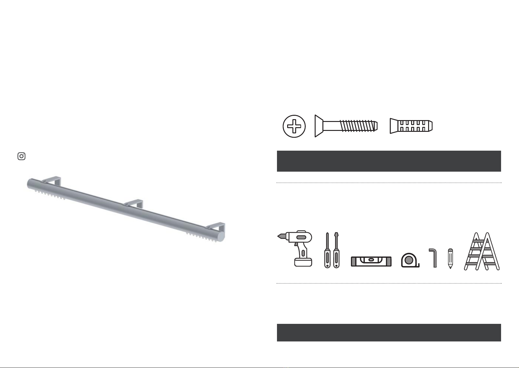
FIXINGS
As a courtesy we have supplied a set of fixings for the system.
These screws and wall plugs are designed to be used in wood and brick walls. We understand our sys-
tems may be used on a variety of materials; drywall, aluminim and steel stud, or lath and plaster.
To properly secure a system onto these or other types of surfaces; appropriate fixings must be inde-
pendently obtained.
Assess your own wall construction and source the appropriate screw type.
PLEASE NOTE, that the enclosed fixings may not be suitable for all wall types.
GLIDERPOLE®
INSTALLATION INSTRUCTIONS
THANK YOU FOR YOUR ORDER
Before fitting this product please ensure that you have thoroughly read these instructions.
We have taken every care to design and manufacture a quality system;
incorrect installation could lead to poor performance.
If any queries arise when reviewing these instructions or during installation please feel free to contact
us for assistance. We will be glad to talk you through the process.
Please retain these instructions for future reference.
SHARE YOUR INSTALL ON INSTAGRAM
TAG: @bradleycollection
Introduction Page 2
FIXINGS Page 2
TOOLS Page 2
CARE & MAINTENANCE Page 2
Flat & Round Gliderpoles Page 3-4
Square Gliderpoles Page 5-6
Alternative Brackets Page 7-8
Adding/Removing Gliders & Rollers Page 9
Corded Systems Page 10
TOOLS
For the installation of the system the following items may be required.
CARE & MAINTENANCE
This gliderpole can be cleaned using a soft cloth and furniture polish.
43
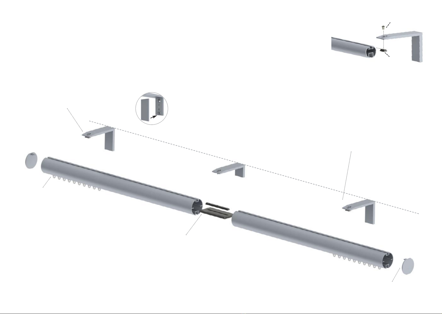
FINIALS
Attach the finials by pushing them into position
and tightening the set screws on the finial.
FITTING GLIDERPOLE TO THE BRACKETS
Offer the gliderpole up to the bracket, and tighten
the button head screw into the fixing insert, ensuring
that the pole is fully secured. Making sure that the
overhangs at each end are equal.
If the gliderpole is made of two connected lengths,
the mid bracket should be fitted on the join.
In this instance remove the fixing insert & screw
the button head screw directly into the joiner.
Fixing inserts are pre-installed into the poles.
Spare fixing inserts are supplied with the brackets.
GLIDERPOLE®FLAT POLE - H36mm (17
/
16”) Round pole - Ø30mm (13
/
16”) • 50mm (2”)
POSITIONING & FIXING
SINGLE & DOUBLE BRACKETS FOR ALTERNATIVE BRACKETS TYPES SEE PAGE 7-8
Brackets should be positioned approximately 100mm (4”) from the ends of the pole.
❶Mark the position of the brackets. For longer poles one or more mid bracket are required,
and should be equally spaced along the system.
PLEASE NOTE, Where systems are made in multiple sections.
Joins must be supported by a mid bracket, which must be fitted directly over the join.
To align the brackets, the top of the mid brackets should be fitted in line with the top of the side brackets.
❷Drill holes & use a suitable wall fixing when attaching the plate to the wall.
❸Screw each bracket into position.
Fit the cover plate, the cover is held in place by magnets.
BRACKET ALIGNMENT BRACKET ALIGNMENT
T-Bar
Button Head Screw
JOINING THE GLIDERPOLE
Gliderpoles are supplied pre-cut to your specified lengths, in
some cases the Gliderpole may be made in two or more parts,
joined by a connector.
Push the joiner* into the pole ends and push the gliderpoles
together. Tighten the set screws in the top channel of the profile.
PLEASE NOTE, All joins must be supported by a bracket.
If there is a gap between joins gliders/rollers may
not run efficiently.
* Internal joiner will vary between gliderpole type and diameter.
ADDING AND REMOVING
GLIDERS/ROLLERS
Gliderpoles are supplied with
gliders/rollers pre-installed, in some
instances it may be necessary to
add or remove gliders, to do this
follow the steps on page 9.
CLICK
65
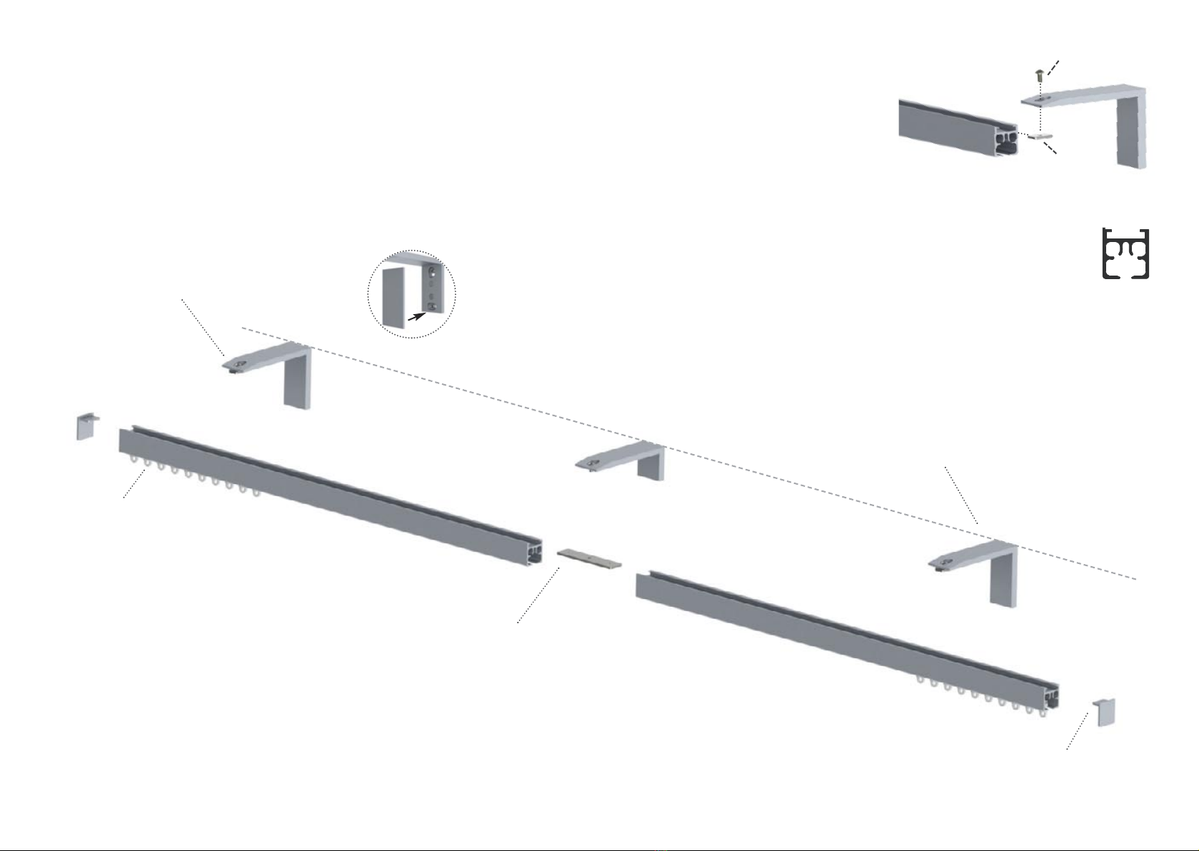
GLIDERPOLE®SQUARE POLE - H27mm (11
/
16”)
FINIALS
Attach the finials by pushing them into position
and tightening the set screws on the finial.
FITTING GLIDERPOLE TO THE BRACKETS
When fitting the track ensure the
higher edge of the profile is at
the front.
Offer the gliderpole up to the bracket, and tighten
the button head screw into the fixing insert, ensuring
that the pole is fully secured. Making sure that the
overhangs at each end are equal.
If the gliderpole is made of two connected lengths,
the mid bracket should be fitted on the join.
In this instance remove the fixing insert & screw
the button head screw directly into the joiner.
Fixing inserts are pre-installed into the poles.
Spare fixing inserts are supplied with the brackets.
JOINING THE GLIDERPOLE
Gliderpoles are supplied pre-cut to your specified lengths, in
some cases the Gliderpole may be made in two or more parts,
joined by a connector.
Push the joiner into the pole ends and push the gliderpoles
together. Tighten the set screws in the top channel of the pro-
file.
PLEASE NOTE, All joins must be supported by a bracket.
If there is a gap between joins gliders/rollers may
not run efficiently.
ADDING AND REMOVING
GLIDERS/ROLLERS
Gliderpoles are supplied with
gliders/rollers pre-installed, in some
instances it may be necessary to
add or remove gliders, to do this
follow the steps on page 9.
POSITIONING & FIXING
SINGLE & DOUBLE BRACKETS FOR ALTERNATIVE BRACKETS TYPES SEE PAGE 7-8
Brackets should be positioned approximately 100mm (4”) from the ends of the pole.
❶Mark the position of the brackets. For longer poles one or more mid bracket are required,
and should be equally spaced along the system.
PLEASE NOTE, Where systems are made in multiple sections.
Joins must be supported by a mid bracket, which must be fitted directly over the join.
To align the brackets, the top of the mid brackets should be fitted in line with the top of the side brackets.
❷Drill holes & use a suitable wall fixing when attaching the plate to the wall.
❸Screw each bracket into position.
Fit the cover plate, the cover is held in place by magnets.
BRACKET ALIGNMENT BRACKET ALIGNMENT
Fixing Insert
Button Head Screw
CLICK
CEILING BRACKETS
Light Duty Ceiling Brackets - Suitable for use with Square • Flat • Round 30mm (13
/
16”) Gliderpoles
Heavy Duty Ceiling Brackets* - Suitable for use with all Gliderpole types
PLEASE NOTE, Bracket must be secured to the Gliderpole before being fitted to the ceiling.
All joins must be supported by a bracket.
Where gliderpoles join, substitute the T-bar/Fixing insert for a joiner.
87
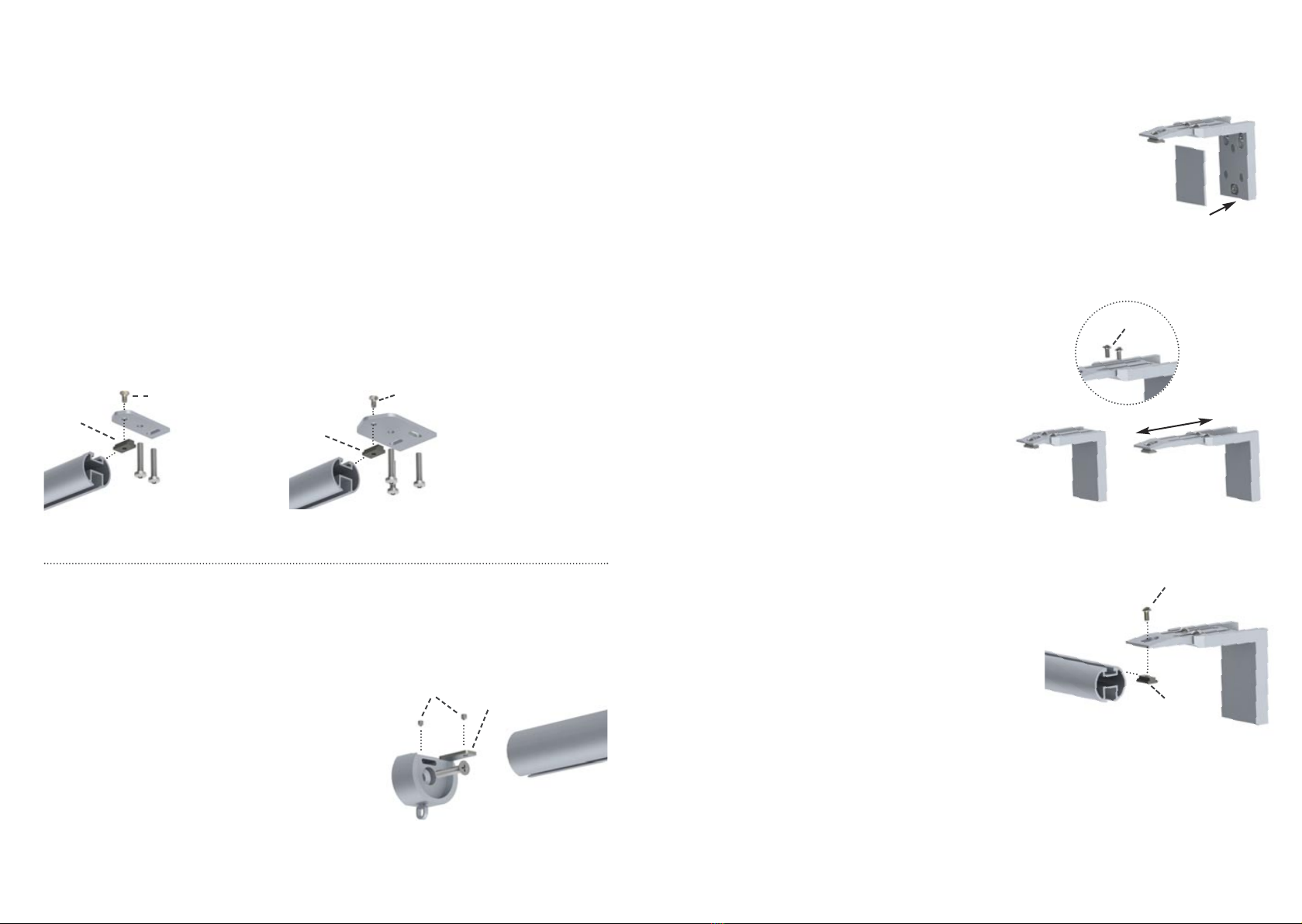
ADJUSTABLE BRACKETS
❶Mark the position of the brackets.
For longer poles a mid bracket is required.
❷Drill holes & use a suitable wall fixing when
attaching the plate to the wall.
❸Screw each bracket into position.
Fit the cover plate, the cover is held in place by
magnets.
❺Screw in the button head screws into the bracket
arm and slide to the desired projection, once the
projection is set tighten the screws to ensure the
bracket arm is firmly secure.
❻Offer the gliderpole up to the bracket, and tighten
the button head screw into the t-bar, ensuring that
the pole is fully secured.
PLEASE NOTE, All joins must be supported by
a bracket. where poles join, substitute the
T-bar/Fixing insert for a joiner.
GLIDERPOLE®ALTERNATIVE BRACKETS
❶Mark the position of the brackets.
❷Drill holes.
❸Locate T-bar/Fixing insert into the top of the pole & tighten the counter sunk screw.
❹Screw each bracket into position, using suitable fixings.
RECESS BRACKETS
PLEASE NOTE, Not suitable for use with ceiling brackets
❶Mark the position of the brackets.
❷Drill holes & use a suitable wall fixing when attaching
the plate to the wall.
❸Screw each bracket into position.
Slide the locking tab inside the top of the pole up
in to the fix plate.
❺Tighten the set screws in both the top of the bracket
and top channel of the pole.
T-Bar/
Fixing Insert
Counter Sunk Screw
T-Bar/
Fixing Insert
Counter
Sunk Screw
Locking Tab
Set Screw
LIGHT DUTY CEILING BRACKET* HEAVY DUTY CEILING BRACKET
* 50mm (2”) Gliderpole not suitable for use with the Light Duty Ceiling Bracket
T-Bar/
Fixing Insert
CLICK
Button Head Screws
Button
Head
Screws
Table of contents
Other The Bradley Collection Indoor Furnishing manuals


Popular Indoor Furnishing manuals by other brands

Regency
Regency LWMS3015 Assembly instructions

Furniture of America
Furniture of America CM7751C Assembly instructions

Safavieh Furniture
Safavieh Furniture Estella CNS5731 manual

PLACES OF STYLE
PLACES OF STYLE Ovalfuss Assembly instruction

Trasman
Trasman 1138 Bo1 Assembly manual

Costway
Costway JV10856 manual


