The Drip Store K001 User manual

Copyright ©2010. 011110 All rights reserved. #26-501
DRIPPER WATERING SCHEDULE
WATERING FREQUENCY
TYPE OF PLANT LENGTH OF WATERING HOT WARM COOL
Flowers, vegetables 30 min – 1 hr 1-2 days 3 days 3-4 days
Small trees, shrubs 1-2 hours 1-2 days 2-3 days 3-4 days
Vines 3-6 hours 1-2 days 2-3 days 3-4 days
Medium trees, shrubs 5-7 hours 2-3 days 2-3 days 4-5 days
Large trees, shrubs 6-8 hours 1-2 days 2-3 days 5-6 days
Pots to 15” 3-5 minutes 1-2 days 2-3 days 4-5 days
Pots over 15” 5-10 minutes 1-2 days 2-3 days 4-5 days
MICRO SPRAYER WATERING SCHEDULE
Flowerbeds, groundcover 30 min – 1 hr 1-2 days 3 days 4-6 days
Small trees 1-2 hours 2-3 days 4-5 days 5-6 days
Medium trees 2-3 hours 2-3 days 4-5 days 6-7 days
Large Trees 2-5 hours 2-3 days 4-5 days 5-7 days
Greenhouses, hothouses 5-10 minutes 2-4 times/day 2 times/2 days 1 time/2 days
DESIGN TIP
• Maximum flow rate recommended for individual drip hose: 220 GPH.
• Minimum spacing between the drippers: 12” to 18”, depending on type of plants.
• Water in the early hours for the best result.
• Allowing the 1/2” drip hose to sit in the sun will make it easier to lay out.
WATERING SCHEDULE
The Drip Store
980 Park Center, Ste. E
Vista, CA 92081
Tel: 760-597-1669
Toll Free: 877-597-1669
Fax: 760-597-1673
INSTALLATION INSTRUCTIONS
Drip & Micro Sprayer
Watering System for
Home Landscape Area
Model K001, K002, K003
INTRODUCTION
Thank you for purchasing one of The Drip Store’s Drip & Micro Sprayer Kits. After installing the drip hose,
turn the water on and flush the system. Then, close the end of the 1/2” drip tubing (model T00X) using
hose end (model A006). Turn the water on again and test the system to make sure that no leaking occurs
along the drip hose connections. Please take the time to read through the enclosed instructions and follow
them step by step. If you have any questions, please call us toll free at 1-877-597-1669 or email: help@
dripirrigation.com.
GENERAL DESCRIPTION
This manual applies to 3models: K001, K002, K003. Use these guidelines for the design and installation of
a cost effective and reliable drip and micro sprayer irrigation system in your landscape area, to promote
efficient water use and to protect natural resources.
ABOUT OUR DRIP AND MICRO SPRAYER KITS
The Drip Store provides you with five different kits. Each kit contains all the parts needed to install a drip
and micro sprayer system for a landscaped area. These kits can be easily installed or expanded above or
below the ground installation in any landscape or garden area.
When installing a low volume irrigation system, please remember that drip and micro sprayer systems
require clean water and operate at a lower pressure than regular sprinkler systems. During the installation,
use the filter and the pressure regulator provided to ensure that your system will remain trouble free for
years to come.
small shrubs, flowers and groundcover vegetable gardens potted plants trees and large shrubs
LEGEND:
Before installation, familiarize yourself
with all the parts that are in the kit
that you have purchased. See the part
list and description in the back of this
instruction booklet.
PLANNING AND DESIGN

INSTALLATION
HEAD ASSEMBLY
Begin the installation at the water source by attaching the backflow device to the faucet. If you decide to
automate your system connect the controller to the faucet using the adapter included and then attach the
backflow device (see B). Thread the “Y” filter to the outlet side of the controller nipple (if used – see B) or
to the 3/4” backflow device (see A). Thread the pressure regulator to the filter and thread the swivel
adapter to the pressure regulator. Attach the 1/2” drip hose to the swivel adapter by pushing and wiggling
the 1/2” drip hose into the adapter.
DISTRIBUTION NETWORKS
Next, lay down the 1/2” drip hose. If you plan to leave it above the ground, allow the drip hose to sit in the
sun before installation. This will make it easier to work with. Use the 1/2” stake (Model S006) to secure
the drip hose to the ground. If you are burying the drip hose, dig a drench about 6” from the roots of your
plants. A shallow trench 5-8” deep is all that is needed to keep the drip hose safe from cultivation
practices. Do not bury the end of the drip hose, allow it to remain on the surface for periodic flushing.
After you install the drip hose, flush the line, then close the end of the drip hose. Turn the water on again
and make sure that water is not leaking. Test the controller, if installed, via the manual button. Make sure
that the water flow direction in each component is in line with the water flow arrows. Finally, program the
controller.
Make a rough sketch of the areas you would like to water. Show the site’s water sources and paved
areas. This will require measuring the area you wish to water. We recommend using graph paper; this
will make drawing to scale easier. Make sure you take into account plant types, location of trees, shrubs,
and groundcovers, planting density and soil type. Based on the plant size and concentration of planting,
determine the number of drippers per plant or the use of micro sprayers and spacing.
When designing your system, make sure to have a design drawing before you start the job. Design
drawings should be clearly readable, to scale. They should also include water location, layout of plant
materials and sidewalks. When the scale layout of the home is complete, it is time to consider the design of
the irrigation system. To cover concentrated areas such as flowerbeds or densely planted groundcover, use
one micro sprayer 5’-6’ apart. For shrubs, vines, and roses use 1 or 2 drippers per plant with a minimum of
12” apart. These drawings illustrate some methods of the many options when designing a system.
34
LF005 LF001
LF007
S005
SF001
1/2” Drip Hose
1/4” Micro Tubing
— MSA00X
— 1/2” Drip Hose
For Models K002, 3 and 4
NOTE: If the backflow device is under constant pressure (when used with a controller), move the backflow
device in front of the controller (Model K004).
/— A015 Backflow Preventer
/— F300 Filter
Fig. A
CONNECTING AND INSTALLING 1/2” FITTINGS
To install the 1/2” fittings, cut the drip hose with a hand pruner, being careful to keep dirt from entering
the line. Hold the fitting in one hand and the drip hose in the other and force the drip hose into the fitting by
wiggling it from side to side. Make sure that the drip hose is pushed about 1/2” inside the fitting.
CONNECTING 1/4” FITTINGS
To install the 1/4” barbs, push the micro tubing over the barbed ends. Soaking the micro tubing in warm
water will make the micro tubing softer and the fittings easier to install.
/— C000 Controller
(Model K004)
— FHTxFNPT Adapter (included with controller)
/— F300 Filter
/— A013 Pressure Regulator
/— A010 3/4” Adapter
/— Drip Hose
/— LF503 3/4” Adapter
Fig. B
/— A013 Pressure Regulator
/— Drip Hose
/— LF503 3/4” Adapter /— A015 Backflow Preventer
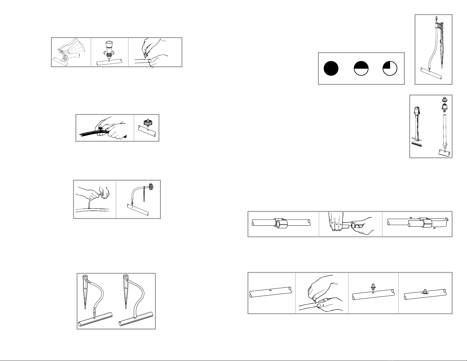
INSTALLING MICRO SPRAYERS (MODEL K003 ONLY)
Install the micro sprayers into the drip hose using the same method as used for
installing a dripper. First remove the spray head. Then install the spike assembly
with the micro tubing and flush the line, then thread the spray head with the pattern
that you selected. We recommend installing the micro sprayers a minimum of 6”
above the surface and at around 5’ to 6’ apart for best coverage.
NOTE: The micro sprayers may be
a complete assembly.
INSTALLING MICRO SPRAYERS ON SEMI RIGID RISERS (KIT K002 ONLY)
Install the micro sprayer on the 1/2” drip hose using the same method as used for
installing the drippers.
Option 1:
Puncture the drip hose using the punch and insert the spray jet directly into
the drip hose. This option will provide you with a very small coverage and is
recommended for individual shrubs.
Option 2:
Puncture the drip hose using the punch and insert the rigid poly riser. Then thread
the spray jet directly into the poly riser. This option will provide you with a larger
coverage. Recommended spacing 3’ to 4’ apart.
INITIAL SYSTEM START-UP
Before turning the system on for the first time, leave the 1/2” drip hose ends open, turn the water on and
allow it to run freely for a few minutes. This will flush out any dirt that may be in the system.
Close the end of the drip hose by using a “figure 8” hose end Model A006. Turn the system on again and
check to see that the drippers and micro sprayers are operating correctly and that no leakage is occurring.
REPAIRING OR PLUGGING A HOLE ON 1/2” DRIP HOSE
If leakage occurs on 1/2” hose at the base of a dripper or micro sprayers, remove the dripper/micro sprayer
and insert a goof plug to close the hole. Reinsert the dripper or micro sprayer in a different area.
USING THE PUNCH
To insert drippers, micro sprayers and 1/4” fittings into the 1/2” drip hose, hold the drip hose in one hand
and apply just enough pressure with the punch to puncture the drip hose.
INSTALLING THE DRIPPERS INTO 1/2” DRIP HOSE
Drippers are installed by punching a hole in the 1/2” drip hose and snapping the larger barbed side into
the drip hose. If the drip hose is buried, the drippers should always be located above the ground. This is
achieved by inserting a 1/4” barb or tee into the drip hose and running a 1/4” micro tubing to the surface
where the dripper is installed to the end of the micro tubing.
INSTALLING THE DRIPPERS TO 1/4” MICRO TUBING
For plants far from the drip hose, first punch a hole in the 1/2” drip hose, then insert a 1/4” barb or tee into
one end of the 1/4” micro tubing and run the micro tubing to the plant. Next, insert the barbed inlet of the
dripper into the end of the micro tubing and secure with a stake, Model S005.
INSTALLING ADJUSTABLE DRIPPERS TO 1/2” DRIP HOSE (KITS K003 AND K004 ONLY)
Adjustable drippers can be installed on 1/2” drip hose using a 1/4” micro tubing. First, insert a 1/4” barb
into the micro tubing, then puncture the drip tubing using the punch and insert the other side of the barb
into the drip hose. Run the 1/4” micro tubing to the shrub or to a tree and attach the micro tubing to the
barb side of the adjustable dripper. You have the option of changing the flow by twisting the dial on top of
the adjustable dripper; flow can be adjusted between 0 to 10 GPH.
5 6
Up to 12’
360° Red
Up to 6’
180° Blue
Up to 6’
90° Black
360ϒ
180ϒ
90ϒ
D032
MSA00X
MS006
A003
SF007
A006
A019
In Model K009
A035
Kit Model K003 & K004
Kit Model K002

Qty Qty Qty Color
Model # K001 K002 K003 Code Description
C000 0 0 0 1 station DC controller with hose or pipe thread
A010 1 1 1 3/4” MNPT x MHT Plastic Nipple
A015 1 1 1 3/4” FHT x 3/4” MHT Backflow device
F300 1 1 1 3/4” FHT x MHT Y filter with 155 mesh
polyester screen
A013 1 1 1 3/4” FHT x MHT 25 PSI preset
pressure regulator
LF503 1 1 1 3/4” FHT x .700 OD swivel adapter
with washer
T002 0 0 0
500’, 1/2” drip hose with .700 OD x .600 ID
T003 1 1 2 100’, 1/2” drip hose with .700 OD x .600 ID
T009 1 1 0 50’, 1/4” micro tubing .245 OD color black
T010 0 0 1 100’, 1/4” micro tubing .245 OD color brown
LF001 3 3 5 1/2” Drip hose coupling .700 OD
LF005 5 5 5 1/2” Drip hose tee .700 OD
LF007 2 2 5 1/2” Drip hose elbow .700 OD
D076 50 50 50 black 1 GPH PC button dripper
D077 0 0 0 green 2 GPH PC button dripper
D078 0 0 0 red 4 GPH PC button dripper
PARTS LIST
Qty Qty Qty Qty Color
Model # K001 K002 K003 Code Description
D032 0 0 20 0-10 GPH adjustable dripper on stake
MS006 0 5 0
Spray jet 10 GPH, 3’ to 13’ diameter, full circle
DF090
0 5 0 green 90° deflectors
DF180 0 5 0 orange 180° deflectors
A003 0 5 0 6” semi-rigid poly riser with 1/4” barb
A018 0 0 0 1/4” barb x 1/4” barb mini-valve
SF001 15 15 15 1/4” barb connector
SF003 0 0 0 1/4” barbed tee
A006 6 6 6 1/2” drip hose figure “8” hose end
SF007 1 1 2 Goof plugs, strip of 10
A019 1 1 1 Tubing punch
A035 0 0 0 Large punch
S006 15 15 30 1/2” drip hose holder stake
S005 15 15 15 1/4” microtubing holder stake, 4”
MSA001 0 0 5
blue/ 360° microspray jet assembly with 13” stake,
red 24” micro tubing and barb. Flow of 12 to
14 GPH and coverage of up to 12’
MSA002 0 0 5 blue/ 180° microspray jet assembly with 13” stake,
blue 24” micro tubing and barb. Flow of 12 to
14 GPH and coverage of up to 12’
MSA003 0 0 5 blue/ 90° microspray jet assembly with 13” stake,
black 24” micro tubing and barb. Flow of 12 to
14 GPH and coverage of up to 12’
I0002 1 1 1 Instruction booklet
1
2
3
4
5
6
7
8
9
10
11
12
13
14
15
16
17
18
19
20
21
22
23
24
25
26
27
28
7 8
This manual suits for next models
2
Table of contents
Other The Drip Store Lawn And Garden Equipment manuals

Popular Lawn And Garden Equipment manuals by other brands


MTF
MTF WBE 2000 V Translation of the original instructions

Acorn Safety
Acorn Safety S0001 Installation, operation and maintenance instructions

SKOTTE GARDEN
SKOTTE GARDEN 102102 installation guide

Smithco
Smithco 45-205 Parts & Service

Garden Gear
Garden Gear G1357 instruction manual

Black & Decker
Black & Decker BDSTGA9701 Assembly instructions