The Fisher Stereophonic 220 User manual
'.:
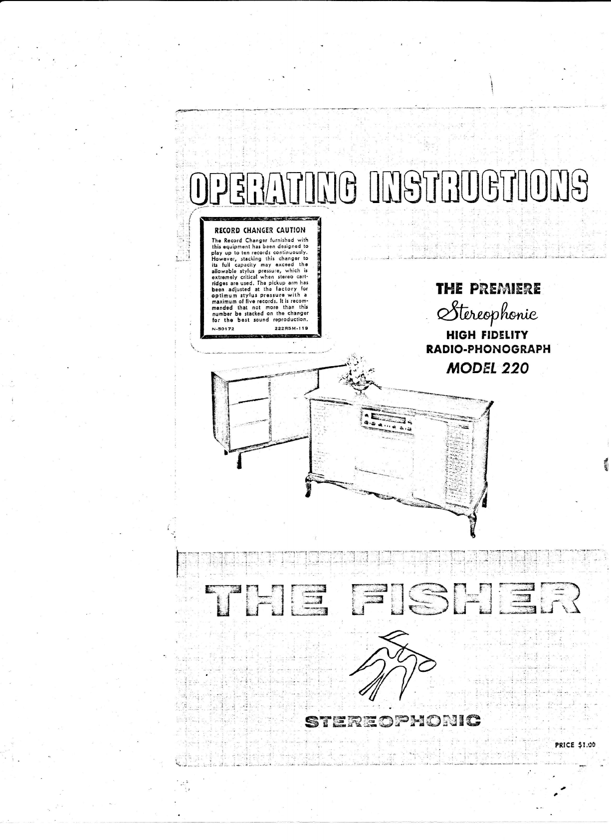
RECORDCHANCIR
CAUTION
lhe Record Ch!nge. lurnished with
thi5 oquipn6nt ha. been designed to
glay up to ten rgcordt continuou5ly.
llow€ver, ita.king this changer to
it! full capacity nay €xeeod lhe
allowable stylur prersure, which i:
extrgmelv critical whed stereo cart'
ridg.s are used, The PickuParm h3s
bsen adiusted at lh. lacto,Y lot
optimum stylsr PreltulE with a
naxinum ol live rEcords.
lt ii recom'
nendsd thal not nore th.n thir
number bc stacked on the chanEor
lor the bert tound toProduction.
N.50t72 22aR5M-l l9
[m8
[m$unuGu[0m8
THEPRESbIIER,E
dt^^pl,*tu
HIGHFIDELITY
RADIO.PHONOGRAPH
1 : : ' -i ; : l- . ,-'
, ;, : ;..;i,..--..t"r",.i *,.:;-*"; " ".,.t
' .*r * d:,-- :.."-; -.-..
tr*H fi fl l-';;s
!t i];lr:J
tl rJ il u:m F*T,3 *-l .rh l"'1 F-l r-:::= r::-\
i 5'lr*J\i ; i, -:3 , ; I
Ll Li q:-J Ll iJ ---m il \}.
4tal a I nfi
i
._l
i$'t' l .--- ..!
:.:
- tr..\.i,
-
.' .::\.:,-j1.. -.-
"
"l;;*oFsi :
l93t First
hightidelity
sound
systems.featuring
a
- beamoower
amplifier,
inverse
feedback,
acous'
tlc ioeaker
compartri:ents
(infinite
baffle
and
bass-tefter)
and
magnetic
cartridges'
1937
Firstelclusively
high
tidelity
TRF
tuner'
featuring
broad-tuninS
20,000
cvcle
fidelity.
llltT First
ttYcunit
high
fidelitysystem
withseparate
spealer
enclosure.
133! First
coarial
speaker
system'
l93EFirst
hiSh
tidelitv
tsner
withamplified
AvC.
1339
First
Dyn3nic
Range
Erpander.
1939
FirstSitay Speaker
in a highfidelity
svstem'
1!39 First
Center+f'Channel
Tuning
Indicator'
tg.dti
Fitst
Preamplifier'
Equalizer
withselective
Ph0'
nograph
equalization.
194,1t
First
Dynamic
Range
Expandef
Y/ithteedback.
t9{9 First
FM-AM
Tuner
Y{ithvariable
AFC.
1952
First
50-watt,
all-triode
amplifier.
1952
First
sell-powered
MastetAudio
Control.
195:l
Firstself-poviered,
electronic
sharp-cut'off
fil'
terststem
{or
h,tl Fdelity
use.
l!53 FirsiUniversal
Horn-Tvpe
speakerEnclosure
for
anY
momlocation
and
anyspeal(er.
t953 Fiist
FM-Atrl
Receiver
witha Cascode
FrontEnd.
1954First
l0w{ost etectronic
Mirer'Fader.
AVEBY FISHER
Fosda aad Preidett,
Firtq Rodio CsPorilio^
The
Msn Behind
the Prodr.lct
//-\vER 20
yEARS
Aco, Avery Fisherintroduced America's first high fidelity radio-
Lrl phonograph.
That instrument attainedinstantrecognitionas
heraldinganew
era
inthe
enjoyment
of reproduced
music.
A number
of thefeatures
of thatearly
high
fidelity
radio-phonograph
wereso basic
that they are usedto this day in all high
fidelity
equipment.
Theengineering
achievements
of AveryFisherand
theworld-wide
reputation
of his
productshave
been
thesubject
of articles
io Fortune,Time,
Pugeant,
The New York Titnes,
Coronet,
Life, Hi7h Fidelity, Esquire,
and otherpublications.
Benefit
concerts
for the NationalSymphony
Orchestra
in Washingtonand the Phila-
delphia
Orchestra,
demonstrating
thegreatadvances
in reproducing
equipment,
used
FISHER.
instruments
to play back the recordings
that had just been
madein the
presenceof theaudience.
"Fascinating
evening,
acousticalll'
andmusically,"
wasthe
fhiloadpnio Inqtirer's comment,"the reproduction
had remarkable
fidelity"' Ttrte
magazine
stated,
"Listeners
could
hardly
tell
thedifference
between
real
andelectronic."
TheFISHER
instrument
youhave
just
purchasedhas
beendesigned
to give
youmany
yearsof pride and enjoyment.
It is the product of a comPany
dedicated
to bringing
ieproOuceO
music
inits
finest
form,
tothehomes
ofAmerica.
If atanytime
you
should
desire
information
or assistance
regarding
theperformance
of your FISHER instru-
ment,
please
donothesitate
towrite
directly
to Avery Fisher,
President,
Fisher
Radio
Corpoiation,
Long IslandCity 1,New York. Your communications
will be welcome'
FISHER 'FIRSTS' - Milestones ln Audio History '"
f954 First
moderately-priced,
professional
FM
Tuner
withTWo
meters.
1955First
PeakPower
lndicator
in high
{idelity.
1955
FirstMaster
Audio
Control
Chassis
viithfive'
position
mxlng
facilities.
1955
First
correctly
equalized,
direct
tape'head
mas'
teraudis
cofltrols
andself{owered
preamplifier.
1955
First to iqcorporate
Power
Monitor
in a home
amplif
ier.
1955First All-Transistorized
PreamPlifier'Equalirer.
1956
Firstdual
dynaoic
limiters
in an FM
tuner
for
hone use.
1955
FirstPerformance
Monitor
in a high quality
amplilier
tor home
use.
l!58 First
FM-AMtuner
v{ith
TWo
meters.
1956
Firstcomplele
graphic
response
curYe
indicator
tor bass
andtreble.
1957first Gold
CascodeFM
Tuner.
195t First
MictoRay
Tuning
Indicator.
t95E
First
Stereophonic
Radio-Phonograph
witi Mag'
neticStereo
Cartridge
1959
First
high-quality
Stereophonic
Remote
Control
SYstem.
tgls Firltcomptete
Stereophonic
FM'AM
Receiver
(FM'
AM
tuner,
audio
control,
4o-watt
amplifier).
!r- -- -!'
/
THE
FISHER
Prerniere
W
High FidelirY
Rsdio-PhonogroPh
Model 22O
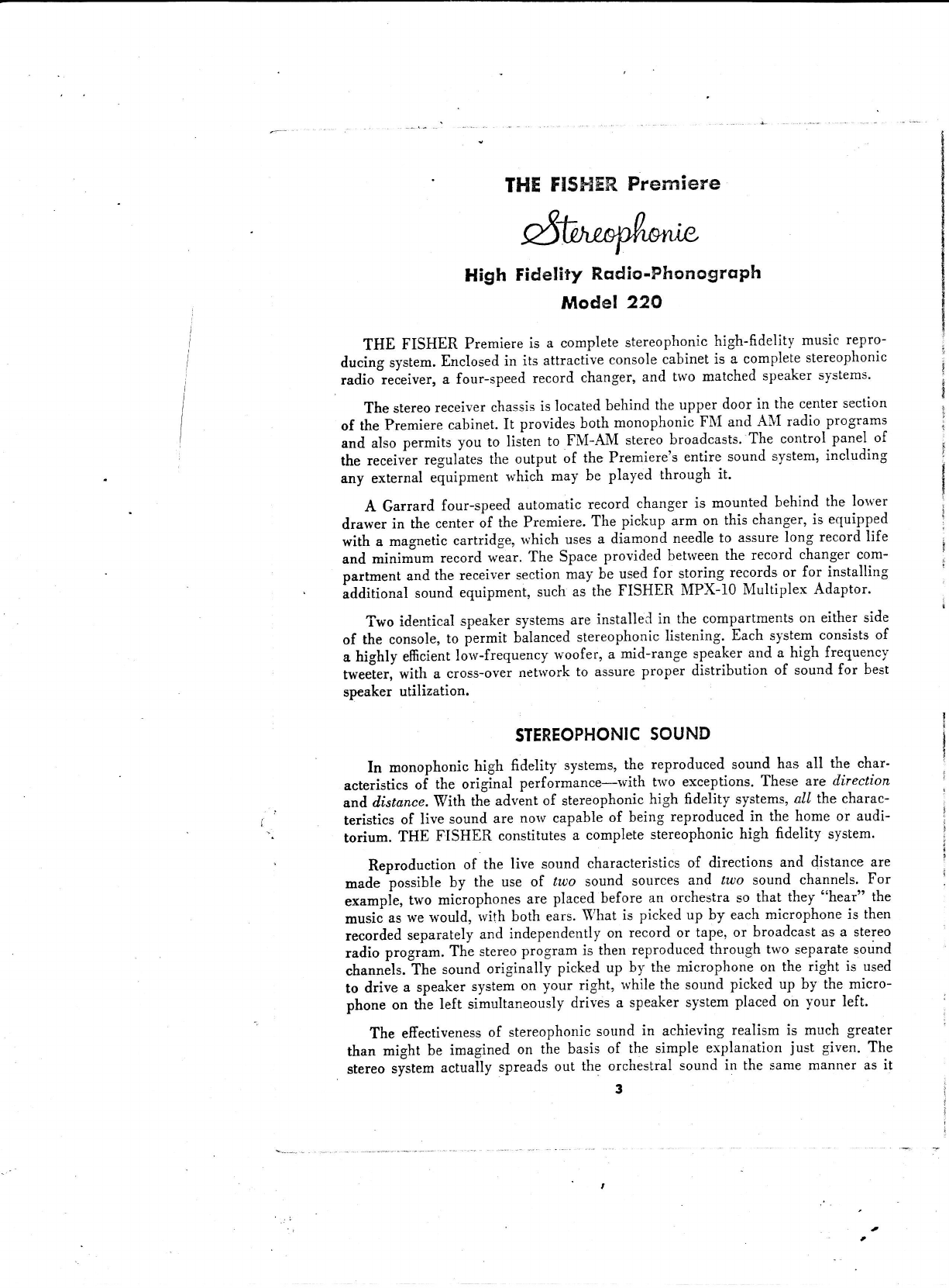
THE FISHER Premiere
is a complete
stereophonic
high-fidelity musicrgpro-
ducing system.
Enclosed
in its attractiveconsole
cabinet
is a complete
stereophonic
radio-receiver,
a four-speedrecord changer,
and two matchedspeaker
systems'
The stereo
receiver
chassis
islocated
behind theupper door in the center
section
of thePremiere
cabinet.
It providesboth monophonicFNI and ANI radio programs
and also permits you to lisien to FNI-AM stereo
broadcasts.'The
control pa-nel
of
the receivesegulates the output of the Premiere's
entire soundsystem,
including
any external equipment which may be played through it.
A Garrard four-speedautomaticrecord changeris mounted behind the lorver
drawer in thecenter
of the Premiere.
The pickup arm on this changer,
is equipped
with a magnetic
cartridge,rvhichuses
a diamond needle
to assure
long recordlife
and mininium record wear.The Space
provided between
the record changercom-
partment andthe receiver
section
maybe used
for stor!1S
re99r{s or for installing
additiotral soundequipment,
suchas the FISHER MPX-10 Multiplex Adaptor.
Two identicalspeaker
systems
are installeC
in the compartments
on either side
of the console,
to permit balanced
stereophonic
listening. Eachsystem consists
of
a highly efficient
lorv-frequency
woofer, a mid-range speaker
and a-high lre-quenc,v
tweeier,
with a "ro.r-ou.i net'lvork
to assure
Proper distribution of soundfor best
speaker
utilization.
STEREOPHONIC
SOUND
In monophonichigh fidelity systems,
the reproducedsound-
has all the char'
acteristics
of the original performance-lvith trvo exceptions.Theseare direction
and.
ilistance.
With theadvent
of stereophonic
high fidelity systems,
all thecharac-
teristics of live soundare norv capableof being reproducedin the home or audi-
torium. THE FISHER constitutes
a completestereophonic
high fidelity system.
Reproduction of the live sound characteristics
of directions and distatrceare
made possible by the use of lroo sound sources and tuto sound channels.For
"*"-pir, two microphones
are placedbefore an orchestra
so that they 'ohear"
-the
music
as
wewould,
rvilh both ears.
Vhat is pickedup by each
microphone
is then
recorded
separately
and independently
on record_ort-apj,or broadcastasa stereo
radio program.The stereo
program is then reproduced
through two separatesound
channels.
the soundoriginally picked up by the microphone on the right is used
to drive a speaker
system
on your right, rvhilethe sound picked_
up by the_micro-
phone on the left simultaneously
drives a speakersystem
placedon your left.
The effectiveness
of stereophonic
sound in achieving realism is mueh greater
than might be imagined on the basis of the simple explanation just given. The
stereo
system
actually spreads
out the orchestralsound in the samemanner as it
3

I
tll
e
!c
=
ul
e
4
ttt
-
I
z
c,
llf
a
o
c
o
t!
(9
z
ET
v,
o
e
z
o
(,!
rl|
ta
o
c
o
o
I
!o
t
I
a
o
o: o
c;
='5
!>
90
90
E.g
o=
I=
sE'
oE
r.3
eg
Io
xi
lio
o
rg
€E
<;
!>
oo
i.9
o:
t:
o<
o>
::
,;j
:'8
<q
o
!:.!
.iE=
L:t
9 Sdci
-o <
o c ;o
"'F:&
Ps1=
-; E<
99- o
.! oo-
iIg
:.*
<E>
9E;
:=
x6
E
.9-
o.:
OF
X:
€=
9€
9's,
2v
E
n:
oo
to
U>
.gE'.
9 J:
Y-9 c
!3-
d *.-c
!q9
g
ie
ry€
.!o
F:
tr<
!c!
qE
:6
-o
6o
*<
g<
>d
G
3e
r!
sH
"iF
;.=
o9
q!
r5
og
,:E
Io
T
:<
;<
.E
q
>5
cv
c
1:l
ol
II
o
),
x>
1n
:6
^E
;i
;3
o
=6
oE
o
F
XI;
:;5
J;',
U::
s54
-1--
dao
:T=
i5:
'-;=
odz
€.s
o
9x€
s=
o
;
.:
€
o
o
F
-
j-
a9
F>
o-
€6
^-
i;
;F
otr
x€<i
l: o
<'3
vPi
-<
6:
gEa
< "'.:
J;
.=
i f <
1e=
5*z
8xi
F€
v
U
=
i
6
.=
€
o
o
o
g
E
Io
ci€
z2
o)
€6
u
o
U
a
F
q
o
-
z
o
=
o
&f
6
ju
e
o
4
F
o9
e-
o6
j
o
oo
e
9o
Hr
J:
6t
€
€€
€€
*
x
€
€
x
z
€z
rXz
+-
>o
tgp
:r!
;c;.:-
x3E
{!-
*o€
o
io
5-a
z'=
OO
)<.5
<5
e
o
!Y
>o
a;.
P
PrE
;Eg
xllg
=n-
o+
T
X-
+3
E'=
-o
oo
x.9
<b
6
I
t
g
3l
o.9
E3
r9
q
=.
=
!
T
o
z
!o
q
o
!
!
Tt
q
'-
E
=
!
o
.4
,-lx-'
x ,s!
-goo
: *:<
:TEE
i; - r'r
i,=cv
diii
x .oH
€a
3
5r
==<
x5"
E=E
I3--
E ;':
odz
: FX
5.:€
;c-
oo
u
ai
e
d
c
.E
.9
=
!
D
o
z
xa'
?-E
9<
xq
-ei
o;
g)u
.:.!
!o
o
o
o
=
!
o
z
.=X
:F
..t 26
'E;E "
dg ^<
:e-P
b
r
!_s
-U
g:fi
i:=
A Y:
vo
ey
d&
U
e
b@'
H
X;
'E
c€(
-E€**
I V<E
"io:
S
E.T,:
) t:L
v.s oq
;i o ov
a6zd€
o
(J
o
F
^O
XZ
o-
:d
t 3= o
- * o{
6 S-;
X A-* r
v c >,:
-! o
4
Hxs
'E;€<
69 -.
i Yx6
FH<E
r'o:f
- t:a
x; bx
9! Ytr
Y32
"=
!c
!
o
;
o
c
o
-
F
a
t
o
E
o
o
E
ll
o
o
€
€
.9
o
o
:
€€
=
o
o
5
3
'a
:
€
a
€
i
>!
96
xY
:b
E-yt€
6= q'i
N- I q
u! F "
E
56E
*;= I
o- c I
x:o-
-gol
o
E
g-
UC
90
o';
:3=
5T€
6.'5
!q
3=
4-
:--
6.:
='
!
.9
o
=
TC
9sB
; l=
^o€
go
qq
!_-
YO
E.
oP
oL
Pq
o: ,'
!
o
o
4
II
l
j
l
j
l
l
I
I
I\
lvould emanate
from the stage.
In other rvords,
instruments
locatedat centerstage
appear to be heard at a point midrvay betrveen
the speakers.
The other orchestral
insiruments
canbelocated
accordingly
from left to right.
This results
in a realism
and clarity neverbefore possible
in high fidelity systems.
It is rvellto emphasize
that stereo
is something
addedto high fidelity to form
a better music repioducing
system,
not a substitute
for it. A monophonic
high
fidelity sysrem
wiil actually surpass
in performance
a stereo
system
19191
!tS!
fidelity standards.
For this reason,
all theadvances
rvhichhavemade
THE FISHER
. t"oild leader in high fidelity for over two decades,
assureyou of the best in
stereophonic
high fidelity instruments.
INSTALIATION
THE FISHER Premiere
operates
on AC only.The AC PorverCordat theback
of the instrument
must be connected
to a line receptacle
supplying 105 to 120
volts at 60 cycles.
A step-up transformer can be used where the line voltage is
lower,a step-down
transformer
whereit is higher.
THE FISHER can be modified
for SO-cycle
operation
by meansof an adaptor
for the recordchanger,
available
from your FISHER Dealer.
The polverconsumed
by the receiversection
of the Premiereis 175 u'atts,
and
and additional15 watts
is supplied
rvhen
the record
changer
is operating.
A 3.2-
ampereslorv-blorv
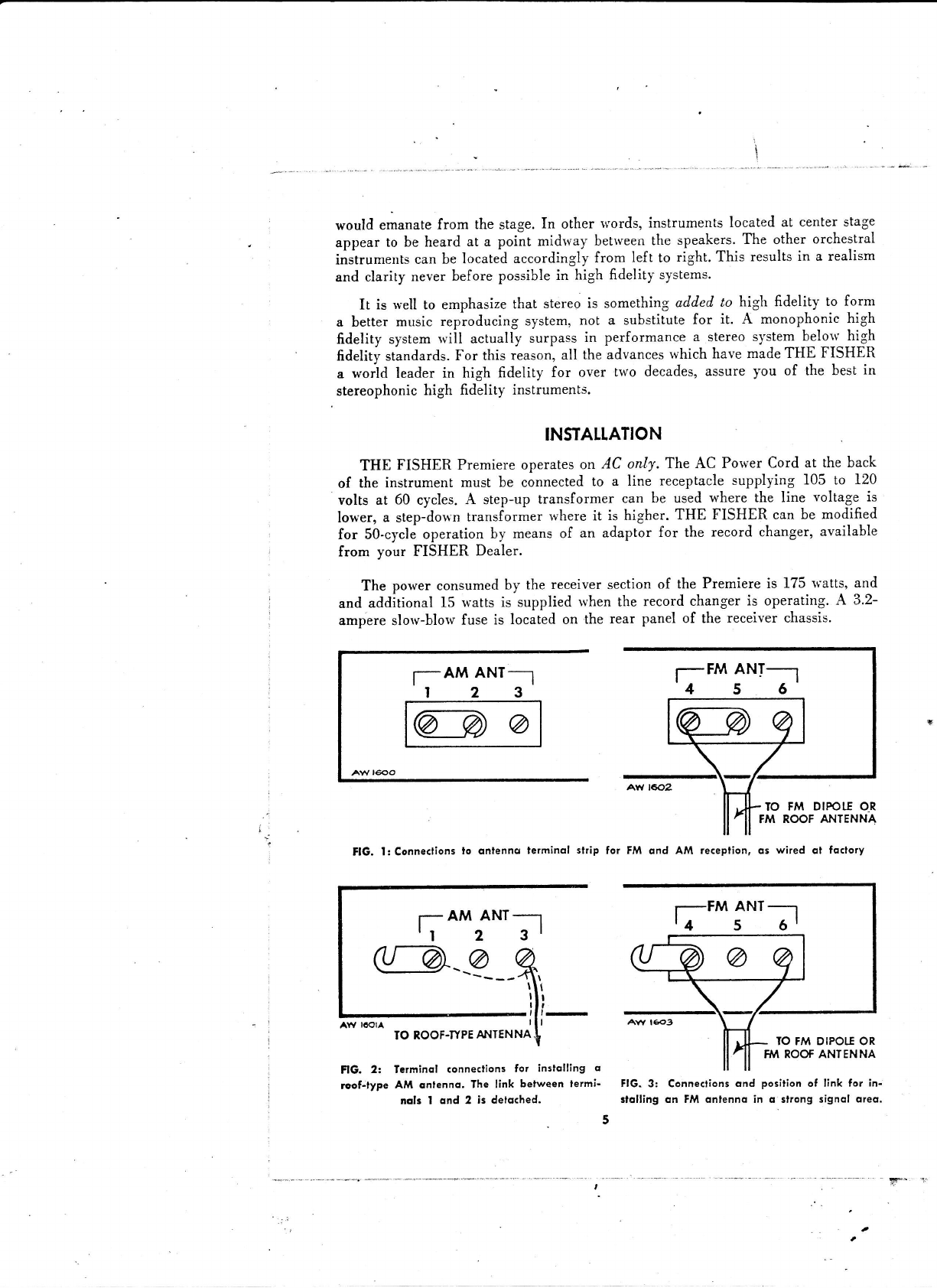
fuse is located on the rear panel of the receiverchassis.
f AMANT-*I f FMANI-_1
456
AW 1602
IO FM DIPOI,TOR
FM ROOFANTENNA
FlG. I: Connections
lo dntenno lerminql slrip for FM qnd AM reception,os wired ol fotlory
r- AM ANT--
It 2 3l
IO ROOF.TYPE
AAITENNA
FlG. 2: Terminal conneslions fot instolling o
roof-type AM qnfenno. The link belween fermi-
ncls I ond 2 i3 detq(hed. FlG. 3: Connections
ond position
of link for in-
slolling on FM onlenno in o slrong signol oreo.
l--FM ANT-]
'4 5 6'
IO FM DIPOTIOR
FM ROOfANTENNA
t

recordchqnget'...
TIIE FISHER is shipped with a holding
screw at the back of the Record Changer
drawer to prevent it from opening in transit,
plus two screws designated by red and white
tags holding the record changer on wood
blocks 6rmly against its mounting shelf. Be
sure that the screws and the wood shipping
blocks have been removed. This is normally
done when the instrument is delivered and
set up. Be sure, also, that the protective cover
<in the phonograph cartridge has been re'
moved, erposing the stylus. If it has not, hold
the pick-up arm firmly and remove the guard
with a fingernail.
Tbe Record Changer should ride on its
ghock mounts. This can be verified by depress'
ing each side of the changer, which should-
spiing back. Consult your FISHER Dealer if
ii does not move downward under hand pres'
gure.
onfennq connections . . .
THE FISHER Premiere is equipped with
a built-in FM dipole antenna for FtrI recep-
tion and with a ferrite loopstick lor AII re-
ception. Figure I shows the antenna connec-
tions, located at the rear of the receiver chas'
sis, as wired at the factory. These antennas
will provide suitable reception in all but ex'
Eem; ftinge' areas or where special local
couditions may afiect the quality of reception.
To reach some weak or distant ANI sta'
tions, a roof-type antenna may be required in
place of the {errite loop antenna. A roof an'
ienna should be connected to terminal 3 and
the link between terminals I and 2 detached,
ae shown in Figure 2. For best reception in
troisy areas, a shielded cable should be used
as the antetrna lead'in. In this case the
shield is connected to lerminal 1.
The AI!1 antetrna is rotatable, and, after
the receiver has been turned on, it may be
twned horizontally to the position which will
provide the best average reception across the
AM band. Before rotating the antenna, loosen
tie mounting screw which Iastens tle loop'
stick to the chassis.The extent to which the
anteona is rotated should not exceed 45 de'
glees.
Il fringe signal areas, an external roof an-
tenna designed for FII reception may be re'
quired. A 300-ohm antenna is recotrrmended
{or this purpose, which should be connected
between terminals 4 and 6 in place of the
Ftr{ dipole originally installed at the factory.
Itr strong signal areas, however, the dipole
is more than srrscient for most purposes. A
roof antenna is ordinarily not required, and
its use may sometimes overload the sensilive
tuner circuits. To prevent any possible over-
load under these conditions, detach the link
belween terminals 4 and 5, as shown in
Figure 3,
otherconnections...
THE FISHER Premiere
is shipped
lrom
the factory with all the components properly
connected to permit you to listen to mono'
phonic and stereophonic phonograph records,
monophonic FII and AII radio programs, and
stereophonic FII-AII broadcasls' In addition,
connections are provided on the rear panel of
ttre receiver to plug in a tape recorder, multi'
plex adaptor or other equipment to be oper-
ated in conjunction with the Premiere. In-
struction for installing and operating auxiliary
equipment oI this type appear on page 12'
ouxilisry receptscle. . .
For your convenience, there is an unused
auxiliary receptacle on the rear panel of the
receiver chassis. Use this receptacle to pro'
vide power to associated equipment, such as
a tape recorder used with the Premiere. ]Iake
sure that the rated poryer consumption of the
equipment connected does not exceed 345
watts. Po'$'er is supplied to the associated
equipment as well as to the Premiere when
the AC switch on the Volume control is
turned on. In this way, your tape recorder or
other equipment plugged into the unit is
turned on and ofi with the Premiere power
switch.
ocpower...
After you have made the connections de-
scribed above, connect the AC power line on
the rear panel oI the Premiere to a source of
AC current. The Premiere will operate be-
tween 105 and 120 volts, 50 or 60 cycles. A
step-up or step-down transformer is necessary
to use the unit at other voltages. Note also
that if you have S0-cycle current, your record
player and other associated equipment may
have to be adapted to operate properly at this
frequency.
Gqution . . .
Now that your connections have been made,
you may be tempted to start operating your
Premiere, belore you have read the rest of
the operating iastructions. 'We strongly urge
you to resist this temptation. The next section
contains important information on operating
the controls which is essential for proper use
and real enjoyment of the Premiere Radio-
Phonograpb.
6

USING
THECONTROLS
All controls
and srvitches
requiredfor normal operation
of the Premiere
are
locatedon the control panelof the receiver
chassis.
The control panel,
shorvn
in
Figure4, hasbeen
carefully
designed
for convenience
and ease
of operation,
and
the control
functions
are clearly marked
on thepanel.
Horvever,
to enable
you to
operate
the
Premiere
effectively,
a brief description
of thepurpose
of eachcontrol
is provided belorv.
qc off sv/itch . . .
This switch is part of the Yolume control
located at the lower right side of the control
panel. When this switch is turned to its ex-
treme counterclockwise position, a click signi'
6es that the AC power has been turned ofi.
'When the knob is rotated clockrvise from
the orr position, AC porver is supplied to the
Premiere and at the same time also to any
associated equipment which may be plugged
into the auxiliary receptacles on the rear
panel of the receiver chassis, The dial glass
is illurninated to show that the power is on.
fmtuning...
The FM Tuning knob on the upper left
side ol the control panel is used to select F\I
stations in the BB to 108 megacycle band.
Turning this knob moves the pointer across
the FilI dial scale.Accurate tuning is achieved
by turning the FII Tuning knob until the dial
pointer is at the approximate frequency of
the Ftr{ station desired, then tuning in with
tbe }IicroRay Tuning Indicator.
fm micro-rqy tuning indicqior . . .
The FII llicroRay Tuning Indicator located
behind the dial glass next to the FII Tuning
knob, is a bright bar of light divided into
two sections by a small, clearly defined, dark
area. When you turn the tuning knob to the
vicinity of an FII station, the gap between
the two sections of the bar of light becomes
smaller. You are tuned to the exact center
of the channel when you have made the gap
ia tle bar of light as small as possible. This
point has been reached when turning the knob
in either direction'rvidens the gap.
omtuning...
The AM Tuning knob, on the upper right
sideof the controlpanel
is usedto select
AII
stations
in the 550to 1600
kilocyclestandard
broadcast
band.Turning this knob moves
the
pointeracross
theAII dial scale,
and also
op-
€rates the A.\I trIicroRayTuning Indicator'
Set the dial pointer to the approximate
fre-
quency of the AII station desired, then tune
in precisely with the XlicroRay Tuning Indi'
caIor.
om micro-roy tuning indicator . . .
The
AII llicroRay
Tuning
Indicator
is lo-
cated behind the dial glass next to the AII
tuning knob. It permits precise tuning of AII
stations in the same manner as the FII
llicroRay described above.
qm bqndwidth swifch . . .
The AII Bandwidth switch, located in the
center of the lront panel, has two positions
marked Atr BRotD and lu sH.{RP.\I''hen there
is no interference from neighboring stations,
the bandryidth switch should be set to eno.ro
position rrhich provides the optinum in band-
width and the best tonal quality. This is es-
peciaily imporiant when listening to FII-A)I
stereo broadcasts in rvhich the :\lI tone qual-
ities should be as nearly equal to FII as pos'
sible. For maximum selectivity and minimum
i-nterferencefrom adjacent stations, switch the
AII Selector to SE.\RP
position.
loggingscqle...
In addition to the scales lor locating FII
and AII stations, the dial glass on the control
panel includes a Logging Scale numbered lrom
0 to 100. With its aid your favorite stations
can be tuned in more easily, since only a two-
digit number need be remembered. The scale
can be used Ior both FII and AlI.
selectorswitch...
The Selector switch in the center of the
control panel permits you to choose the pro-
gram material which is played through the
Premiere. The five positions of this srvitch and
their respectivefunctions are as follows:
FM-AM: Use this position to listen to mono-
phonic FII or AII radio programs and to
FII-AII stereo broadcasts.
PHONO: Use this position for playing steieo.
phonic and monophonic records. Note, horv'
ever, that 78-rpm records must not be played
t'
i
i
rj
II
I
I
I
I
I
I
{
I
I
I
I
l
I
I
I
,"i
1
I
I
I
i
l.
I
I
lI
I
I
a
ss,
=q
s]
Ira
oij
\x a\?
L': t{
t>
lo
d
3!r-r -
aEr 16
uo=:
3.3 0
e.n E
*,V 2"
=!E
:
=
5l-ls
,il-**l:g
n:l--lB
,.A,t
tVu=
=gn,t
9:3 5
i''\, H
t.*
E?
nz ".
^\ \ / F .
d \-/r
'5.
^E
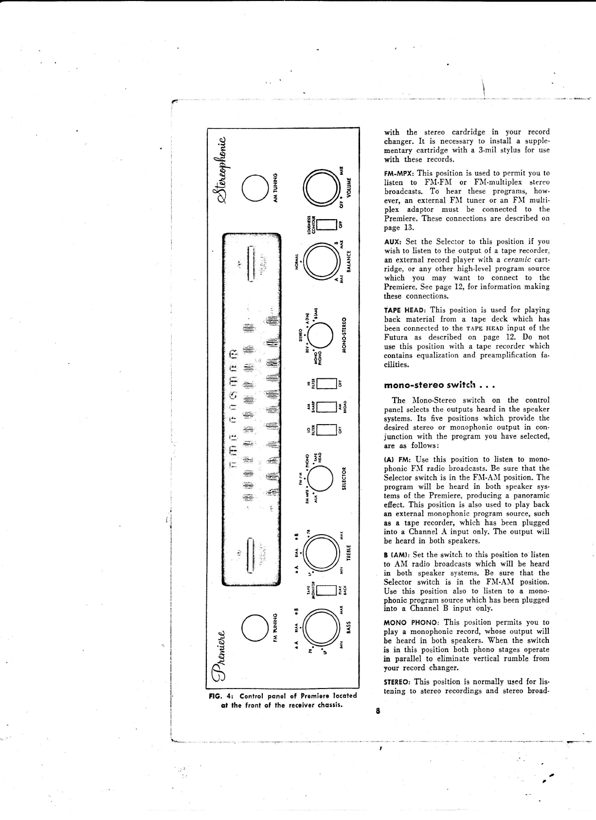
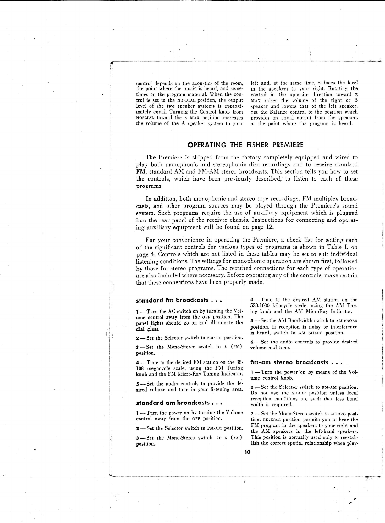
FlG. 4: Control ponel of Premierelocoled
ot the fronf of the recsiverchosris. g
with the stereo cardridge in your record
changer. It is necessary to install a supple'
mentary cartridge with a 3-mil stylus for use
with tiese records.
FM-MPXr
This position is used to permit you to
listen to FII-FXI or FilI.multiplex stereo
broadcasts. To hear these programs, how-
ever, an external FII tuner or an FII multi-
plex adaptor must be connected to the
Premiere. These connections are described on
page 13.
AUX: Set the Selector to this position if you
wish to listen to the output of a tape recorder,
an external record player with a cerantic cart-
ridge, or any other highJevel program source
which you may want to connect to the
Premiere. See page 12, for information making
these connections.
TAPE
HEAD: This position is used for playing
back material from a tape deck which has
been connected to the TArE rlEADinput of the
Futura as described on page 12. Do not
use this position with a tape recorder which
contains equalization and preamplification fa-
cilities.
mono-stereoswitch...
The trIono-Stereo switch on the control
panel selects the outputs heard in the speaker
systems. Its five positions which provide the
desired stereo or monophonic output in con-
junction with the program you have selected,
are as follows;
(Al FM: Use this position to listen to mono-
phonic FII radio broadcasts. Be sure that the
Selector switch is in the FII-AII position. The
program will be heard in both speaker sys-
tems of the Premiere, producing a panoramic
efiect. This position is also used to play back
aa external monophonic program source, such
as a tap€ recorder, which has been plugged
into a Channel A input only. The output will
be heard in both speakers.
I (AMl: Set the switch to this position to listen
to AII radio broadcasts which will be heard
in both speaker systems. Be sure that the
Selector switch is in the FI'I-AII position.
Use this position also to listen to a mono-
phonic prograrn sourcewhich has been plugged
into a Channel B input only.
MONO PHONO: This position permits you to
play a monophonic record, whose output will
be beard in both speakers. When tbe switch
is in this position both phono stages operate
in parallel to eliminate vertical rumble from
your record changer.
STEREO:
This position is normally used for lis-
tening to stereo recordings and stereo broad-
T

6asts. With the switch in this position, the
spatial arrangement of the orchestra is repro-
duced in your speakers as it rtas originally
recorded-or broadcast, rvith the strings heard
predominantly at the left and the brass to
your right. If you have an external stereo
input connected, the Channel --l input rvill
be heard in the speakers to )our left, and the
Channel B input in the right-hand speakers.
REV:This position reverses the normal stereo
listening arrangement by feeding the FII or
Channel A input to the speakers on the right
ind the AII or Channel B input to the speak-
ers on the Ieft side. This position rvill nor-
mally be used only if a tape recording or
other stereo input has been reversed channel-
wise and you wish to restore the original
spatial arrangement of the orchestra.
oudiocontrols...
There are six audio controls on the front
panel of the Premiere, rvhich permit you to
vary the volume and tonal characteristics of
progr:am material. The Bass and Treble con-
trol knobs provide individual tone regulation
in each channel, iI desired, to ryatch the
acoustic conditions of your iiving room. The
other controls are ganged to provide identical
cheracteristics in both output channels for
convenience in operating your sound system.
VOIUME: This is the master yolume control
which controls the level simultaneously at bo:h
speakers. Turning the knob away from orr to
uax position, increases the sound output from
both speaker systems,
BA55: The Bass Tone Control is a dual knob
which permits you to regulate the intensities
of the low-frequency or bass tones in either
the FII (A) channel A or in the FII (B)
Channel B, or in both channels simultaneously.
The smaller knob, marked rvith a gold tri-
angle, controls the bass response in Channel
,{" The larger knob, marked rvith a gold dot,
regulates the bass tone in Channel B.
The knobs are friction loaded, so that rvhen
one is turned tbe other turns with it, thereby
perm.itting simultaneous contol of both chan-
nels. II individual control of the bass is de-
sired in Channel A, hold the large Channel B
kaob with one hand and rotaie the small
Cbannel A brob to the desired position with
the other hand. Reverse the procedure to reg-
ulate the bass tones in Channel B.
The three positions marked on the Bass
contro! indicate the recommended points at
whicb the control should be set to assure
correct basstones for the various phono equali.
eations used with difierent types of records.
Use the nr,r.l position for all stereopbonic and
new monophonic records. This also represents
the "normal" position when listening to FII
and AII radio.
Set switch to r-e position for long-playing
records produced before 1955.The 78 position
is Ior playing old-type shellac records rvhich
'were cut at 78 rpm. Avoid extreme settings
of the Bass control at high volume as this may
cause distortion and rumble at the speakers.
TREBTE:The Treble Tone Control is operated
by a dual-knob, marked with a triangle for
Channel A (FlI) and wirh a dot for Channel
B (FlI). This dual control is used to regulate
the treble response in each channel in the
same manner as descri.bedabove for the Bass
Tone Control.
The Treble tone control alters the intensity
of the high-Irequency treble tones. The knob
is turned to the right towards rrAx to provide
greater treble intensity, and to the lelt towards
MI:{ for less treble, There are three positions
on the Treble control which indicate the posi-
tions to which the control should be set to
provide correct treble equalization for RIAA,
LP or 78 rpm records. If uniform response is
desired, set this switch to RL\A.
IOUDNESSCONTOUR:
r\s the relative volume
of sound is reduced, our natural hearing sen-
sitivity drops ofi more rapidly in the bass and
upper treble regions than it doesin the middie
Irequency range. The Loudness Coniour switch
pernrits you to l.isten to program material at
low levels rvithout being deprived of the high
and low frequencies which would otherwise
be lost. Setting this srvitch to LouDriEsscoti-
TouR automatically increases tbe amount of
loudness compensation as you lorver the VoI-
ume control and decreases this compensation
as you increase the vol.ume.
[O FIITER:
The Low Filter srvitch is used to
eliminate possible rumble or other low-fre-
quency disturbances, Turn this sryitch to Lo
rtrrrn position iI you encounter rumble or
ottrer undesirable lorv frequencies when play-
ing your record player or tape deck.
Hl FTLTER:
Set this switch to nt rnrrn position
to eliminate needle scratch or other unlvanted
high-frequency sounds originating in your
phonograph records. This position may also
be used to suppress whistling and other high-
frequency interference rrhich may be present
in some AII broadcasts.
bqlance . . .
The Balance control, provides the correct
balance between the speaker systems in the
Premiere for Iistening to stereophonic pro-
grams, Tbe proper setting of the Balance
I
,l-. -*
control depends on the acoustics of the room,
the point where the music is heard, and some-
times on the program material. When the con.
trol is set to the NoRIIAL position, the output
level of ihe two speaker systems is approxi-
mately equal. Turning the Control knob from
NoRlrAL toward the e lr.rx position increases
the volume of the A speaker system to your
left and, at the same time, reduces the level
in the speakers to your right. Rotating the
control in the opposite direction to\yard B
rrex raises the volume of the right or B
speaker and lowers that of the left speaker.
Set the Balance control to the position which
provides an equal outpu! from the speakers
at the point rvhere the program is heard.
OPERATING
THEFISHERPREMIERE
The Premiere
is shipped
from the factory completelyequippedand rvired
to
play both monophonic
and stereophonic
disc recordings
urld to receive
standard
FM, standardAM and FNI-Ali stereobroadcasts.
This sectiontellsyou hoiv to set
the controls, 'rvhich
have been previously described,to listbn to each of these
Programs.
In addition,
both monophonicandstereo
taperecordings,FNImultiplexbroad-
casts,
and other program sources
may be played through the Premiere's
sound
system.
Such
programs
requirethe useof auxiliary equipmentwhich is plugged
into therearpanelof thereceiverchassis.Instructionsfor connecting
and operat-
ing auxiliary equipment
will be found on page12.
For your convenience
in operating the Premiere,a checklist for settingeach
of the significant controls for various types of programs is shorvnin Table I, on
page
4. Controls
which arenot listedin thesetablesmay be setto suit individual
listeningconditions.
The settings
for monophonic
operationareshorvnfirst,follorved
by those
for stereo
programs.
The requiredconnections
for each
type of operation
arealso
included
rvhere
necessary.
Before
operatingany
of thecontrols,make
certain
that these
connections
have
been
properly made.
stsndqrd fm broqdcssts . . .
| -Tura theAC switcb
onbyturningtheVol'
ume controlawayfrom the orr position.The
panellights shouldgo on and illuminate the
dial glass.
2-Set theSelector
s'rvitch
to rn'rI position.
3- Set the Mono-Stereoswitch to r, (r*r)
position.
4-Tune to thedesired
FII station
onthe 88-
108 megacycle
scale,using the FfI Tuning
knobandtheFi\I trIicro-Ray
Tuning Indicator.
5-Set theaudiocontrols
to provide
thede-
siredvolumeand tone in your listeningarea.
stondqrd qm broqdcqsls.. .
| -Turn thepoweron by turningtheVolume
control
awayIrom the orr position.
2-Set theSelector
switch
to rtt-,rlt position.
3-Set the ilIono-Stereoswitch to r (elr)
position.
4-Tune to the desired AII station on the
550-1600 kilocycle scale, using the AII Tun-
ing knob and the AII trIicroRay Indicator.
5 * Set the Al{ Bandwidth s'rvitch
to .{}t BRoAD
position, If reception is noisy or interference
is heard, switch to A1r sHARp position.
c-Set the audio controls to nrovide desired
volume and tone.
fm-om s?ereo broqdcqsts . . .
I - Turn the power on by means of the Vol-
ume control knob.
2 -Set the Selector switch to rn-err position.
Do not use the sx-rne position unless local
reception conditions are such that less band
width is required.
3- Set the llono,Stereo srvitch to srrnro posi-
tion. REvERsE
position permits you to hear the
FII program in the speakersto your right and
the AII speakers in the left-hand speakers.
This position is normally used only to reestab-
lish the correct spatial relationship vhen play-
l0
t'
tIi.
ing d recording which has been made with the
channels reversed.
4 - Tune to the respective frequencies of ihe
FM and AII stations which are transmitting
the stereo program, using the FIl and AtrI
Tuning knobs and the corresponding MicroRay
Indicators.
5 - Set the AII Bandwidth switch to AMBRoAD
position. Do not use the sn.lnp position unless
local reception conditions are such that less
band widtb is required.
6 - Set the audio controls to provide the de'
sired volume and tone, and set the Balance
control for best stereophonic listening.
monoPhonic re(ordings . . .
| - Turn the Volumecontrolknob so that
power is applied to the set.
2 - Set the Selecror switch to rroxo position'
3-Set the tlono-Stereo switch to MoNo'
rnoxo position.
4 - Set the Bass and Treble tone controls for
both channels to RIAA position, if the mono'
phonic record you are playing is a new
iecord which has been made with this equali-
zation. For 33-1,/3 and 45 rpm records made
before 1955, use the r,r position.
5 - Place the record changer in operation in
accordance with the separate instruction book
Iurnished. To obtain the best sound reproduc-
tion, it is recommended that not more than
,tlree to 6ve records be stacked on the
changer.
6 - Set the remaining audio controls to pro-
vide the desired volume, loudness control and
6"ltering.
Varning! The stereo cartridge supplied with
your changer must not be used to play 78 rpm
records. If you wish to play these old sheilac
records, it will be necessary to instail a
second plug-in cartridge, which is available
from your Fisher dealer. You may also con-
nect an external record player with a ceramic
cartridge to the Premiere, as described on
page 13. To provide proper equalization with
these records. set the tone controls to ?8
position.
stereophonic recordings . . .
t - Turn the Volume control knob so that
power is applied.
2 - Set the Selector switoh to rnoxo position.
3 - Set the Nfono-Stereo
switch to srERsoposi-
tion. Use the nsvrnse position if you wish to
transpose the output channels.
4 - Set the Bass and Treble tone controls to
nn.l positions to provide normal equalization
in each channel. Il you wish to vary the tone
in either channel. set the dual Bass and Treble
knobs as required.
5 - Place the record changer in operation in
accordance with the operating instructions fur'
nished for the changer. Do not stack more
than three to 6ve records on the spindle to
insure good listening results.
6 - Set the remaining audio controls as re'
quired and adjust the Balance control to pro'
vide the best stereoPhonic efiect.
INSTAtttNG
AND OPERATING
ASSOCIATED
EQUIPMENT
In addition to providing FM and A1\{ broadcastsand playing both stereo-
phonic and monophonic phonograph records,external sound sources
can be con-
nect€dto the Premiereto provide other high fidelity program material. Associated
equipment which canbe usedrvith the Fremiere include a tape recorder or tape
deck, an adaptor for FM multiplex reception,an external FM tuner for FM-FII
'stereobroadcasts,
and an externalrecord player rvith a ceramic cartridge.
' Instructions for connectingand operating these auxiliary sound sources
are
cbntainedbelorv.
All input and output connections
are made to the jack bracket
,locatedon the rear panel of the receiverchassis,
asshown in Figure 5.
.-fl
F-*',r

1
i
,t
I
:
1; i
AEITA 6N{rcTIONI @a
CHANXEL
A CHANNEL
A
rdttutrt-lxruT'-
@e9 q_9_9_9
* .oo. *on euxmrxllllrff,f
o
rsPK A---lrlMP 8-.l [sPK
cl
t6taoaa16tGx T-rEvEl s€r------l ATIXITIARY
ECETACtES
PHASI
m@@@o@@ @@@o @@
!@@@
t^
,^\ n\
(t i> (/ > {ru*)(/Z)
-.W \./ \/I!,/
6w stw .tii",if.
FlG.5: Reor
pon€l of the receiverchossisshowing locotion
of iock brocket
for moking conneclions
lo exlernql equipment.
l
.
\
tqperecorder...
. A standard tape recorder, either stereo'
phonic or monophonic, can be used for two
purposes with the Premiere. First, it can be
used to record on tape A[1 or FM broadcasts
or phonograph records being piayed through
tle Premiere sound system. Secondly, it will
play back through the Premiere sound sy-stem
ptogt"^ material which has previously been
recorded on magnetic tape. Permanent connec'
tions between the tape recorder and the rear
panel o{ the receiver chassis to permit both
iunctions to be carried out may be made as
indicated below.
II your recorder utilizes separate record and
playback heads, connect a cable between the
icnon ourpur jack on the Premiere and the
input or record jack on your tape recorder'
Connect another cable between the output or
playback jack on the recorder and the ilIoNI'
ToR rNPUTjack on the Premiere. If you are
using a stereo recorder, make these connec'
tions to both the Channel A and Channel B
RcRDR
and MoNIToRjacks. If a monophonic re-
corder is being used, make these connections
ao either Channel A or Channel B. These con'
trections will permit you not only to record
and play back as described above, but also to
monitor, or play back, material as you re-
cord it.
II your recorder utilizes a common head for
both recording and playback, the output cable
Irom the tape recorder should be connected to
the AUx input on the Premiere, If the eux in'
put is already occupied by another program
source,
you may use the lroxtroR or MPx in-
put, Another cable is connected between the
ncRDRourPUT jack on the Premiere and the
input or record jack on your tape recorder. If
you irre using a stereo recorder, make these
connections in both the A and B channels'
With a monophonic recorder, connect either
A or B. Using the AUxinput provides a sirong-
er playback signal
Set the Selector switch on the Premiere to
prroNo, or FM-Alr depending on which pro.
gram source you are recording on magnetic
tape. For playing back taped programs, set the
Selector to AUx or FM-[rPx depending on in'
put connections.
If you are using a monophonic tape re.
corder se! the Mono-stereo switch on the Pre'
miere control panel to A or B, depending on
whether the tape recorder has been connected
to the A or B channel. A stereo recorder
should be set to srEREo,or to REVERSEif you
wish to reverse the tape output channels,
The tape monitor switch, located on the
front panel, has two positions, uotrlton and
pLAyaAcK. If the tape recorder has been con-
nected to the tr{onitor Inputs of the Premiere,
set this switch to xroNlroR. This wiil pernit
you to hear the program as you have recorded
it. To play back program material from a tape
recorder which is not connected to the }Ioni-
tor Inputs, set the Tape }fonitor switch to
PLAYBACK.
Set the volume, tone and balance controls on
the Premiere as required. Operate the tape
recorder in accordance with the instructions
furnished with it.
tapedeck...
A tape deck is a tape transport mechanism
without a preamplifier. It is connected to a
sound system to provide playback from re-
corded tapes. If you have a stereo tape deck,
connect the A and B output cables to the re-
spective inputs marked rApE HEAD in both
Channel A and Channel B. A monophonic
tape deck may be connected to either the
Channel A or Channel B tlpp HEAD
input.
The reps nr.lo inputs provide the pream-
plification and equalization required when con-
nected directly to tape heads.Do not use these
inputs lor standard, tape record,ers in which
i{
T
I
l2
L

playback preamplifers are incorporated. These
iecordets should be connected as indicated un'
der Tape Recorder.
Set the Selector srvitch on the Premiere to
T.{pE HEAD.Turn the llono-Stereo switch to
srEREo if you are using a stereo tape deck'
With a monophonic tape deck, set the ]Iono-
Stereo switch to A or B position, depending on
the Channel to rvhich lhe tape deck has been
corulected. Turn the Tape llonitor switch to
PLAYE.TCK.
Set ttre volume, tone and balance controls
as required, For other information on oper-
, ating the tape deck, see the instructions fur'
nished with it.
multiplexsdqPtor...
A multiplex adaptor, such as the FISHER
model trIPX-l0, is required to receive multi'
plex stereocasts.
The adaptor can be perma'
Dently connected to the Premiere receiver
chassis to hear these broadcasts whenever
they are available. Connect a cable from the
MPx ourPUT jack on the rear panel of the re'
ceiver to the appropriate input jack on your
multiplex adaptor. Then connect the Channel
A and Channel B ourpur jacks of the adaptor
to the coresponding urx Ixeur jacks of the
. Premiere. See the operating instructions fur-
nished with your multiplex adaptor {or addi-
tional inormation.
Set the Selector switch on the Premiere con'
tiol panel to Flr-)IPx. The ]Iono'Stereo srvitch
shoutd be set to srEREo.
Set the Tuning knob
to the FII station which is transmitting the
stereo broadcast.The volume and tone controls
on the Futura are set as required. The sepa-
ration and other controls on the adaptor should
be operated as described in the instructions
furnished with the multiplex adaptor.
The Fisber IIPX-10 llultiplex Adaptor can
be readily fitted into the record storage com'
partment in the Premiere cabinet.
fm-fmsfereo...
This rype of stereo broadcast, available in
some areas, requires an external FII or FII-
A.r\I tuner in addition to tbe receiver in the
Premiere. Connect this external tuner to the
Channel B trpx llpur jack on tire rear panel
of the Premiere's receiver chassis' Also con'
nect a jumper betw-eenthe rlr ouirur jack
and the Channel A rrrx txeur jack.
Caution! The shielded cable leads from the
Flr ourpur and rrpx ourPur jacks should be
kept as far away as possible from the FJI
anlenna, antenna lead-in or antenna terminals.
The receiver in the Premiere should supply
the left or A channel of the stereo broadcast,
and the external tuner should provide the B
channel. It i{ill be necessaryfor you to ascer-
tain from your neuspaper which FII station
is broadcasting the respective channels and to
set your tuners accordinglY.
Set the Selector switch on the Premiere
conirol panel to FII-upx, and the ]Iono-Stereo
switch to srEREo.The tone and balance con'
trols on the Premiere control panel should be
set as required.
exlernql re€ord ployer . . .
A second record player with a ceramic cat'
tridge may be connected to the Premiere to
provide another phonograph source. If the ex-
ternal record player is equipped with. a 3-mil
sty.lus,you can play 78 rpm records without
changing the cartridge in the Premiere record
changer, The external record player may be
equipped with either a monophonic or a
stereophonic cartridge.
II the external record player or changer you
are using has a ceramic slereo cartridge, con-
nect the leads from the cartridge to the inputs
on the Premiere jack bracket marked ,rux.
Connect both Channel A and Channel B. A
monophonic ceramic cartridge may be con-
nected to the lux input in either channel. The
input impedance ol the .lux jack is 2 meg-
ohms and is, therefore, highly suitable for
ceramic cartridges.
Note! An external record player with a mag-
zeac cartridge must not be connected to the
AUx inputs. If you wish to use an external
player o{ this type, it can only be plugged into
the inputs marked tIcN PHoNo, into rvhich
the Premiere's record changer is normally
plugged.
MAINTENANCE
AND ADJUSTMENTS
There are five Level Setsand a PhaseReversingsrvitch located on the rear
panelof the
Premiere
receiver
chassis
(see
Figure5). Thesecontrols
may require
some
adjustment
whentheconsole
is firstinstalled,
but theyarenot normally used
in subseguent
operation. t3
'**- E-'-'"F
,
$
levelsets...
Tbere are 6ve Level Sets marked Phono
A, Phono B, ilIPX A, IIPX B, aad AlI. The
Phono and the AII Level sets have been ad-
justed at ttre lactory to provide a uniform out-
put lyith various program sources which are
standardized with the unvarying FII output.
II a tape recorder or multiplex adaptor has
been connected to the Premiere, the IIPX
Level Sets will probably require adjustment
from the ilIaximum position in rvhich they are
shipped from the factory. Turn the IIPX Level
iet counterclockwise until the volume of the
tape recorder or trIPX stereo program is equal
to the other levels.
Note! The Phono level set can also be used
to adjust the level of tape deck inputs.
phasereversing switch . . .
The Phase Reversing switch provides a
means of compensating for improperly phased
speakers. Since the. speaker systems in the
Premiere have been properly phased at the
factory, this srvitch is not normally used.
If the speakers are out of phase,
it is neces'
sary to reverse the leads to one of the speak-
ers. This .is accomplished by the Phase Re-
versing switch which electrically reverses the
leads to Speaker B. Set this switch to REvERsE
positiou..
tube locotion snd functions
. . .
A tube loeation diagram appears on the
model label oI tbe Premiere,
locatedon the
rear of the cabinet.
lbe tube fuactions
oI the
receiverchassis
are as follows:
FM SECT|oN:
Vl-Cascode
RF Stage (ECCBJ/
6AQB); V2-IIixer and Oscillator (ECC85/
6AQB)
; V3, V4- IF Amplifier (6AU6); v5-
Limiter and IF Amplifier (6AU6); V6-trIicro-
Ray Tuning Indicator (EIIBd/6FG6). l
lc i'r.'t
AM SECTION:
V7-TunedRF Amplifier 16BJ6);
V8-lIixer, Oscillator and IF Amplifier
(ECH8I/6AJ8) ; Y9-IF Amplifier and
Demod'
ulator (EBF89)
; Vl0-llicroRay Tuning Indi-
cator (E}I84,/6FG6),
POWERSUPPTY:
V1l-Rectifier for Amplifiers
(G234/5AR4) ; Vl2-Rectilier for Tuners
G.A0/6V4).
CHANNET
B AMPIIFIER:
Vl3-Tone control am-
pliiler (7025/ECCB3,/12AX7) ; Vl4-Driver and
Phase Inverter (7199) I V15, Vf6-Push-Pull
Power Amplifier (7189) I Vl7-Phono-Tape Pre-
amplifier \iO2S/ECCB3/
l2AX7) i'
CHANNEL
A AIAPUFIER:
\'18-Phono-Tape Pre-
amplifier (7025/ECCB3/ 12-'\X?) ; V19-Tone-
Control Amplifier (7025/ECCB3/12AX7) ; V20-
Driver and Phase Tnverter (7199)
i Y21,22-
Push-pull Porver Amplifier (?189). '' , ) +7
There is also a matched pair of crystal di-
odes in the FfI detector stage Iocated on the
top of the FJI discriminator transformer.
replqcing pqne! lighrs . . .
When tle AC power is turned on, two panel
lights will go on to illuminate the dial glass
of the Premiere control panel. These lamps
are located behind the front panel on either
side o{ the dial glass, and are not visible. To
replace these bulbs, it is necessaryto remove
the front panel, first disconnecting the AC
cord as a safety precaution.
The front panel is held in place by means
of four hex nuts located behind the Volume,
Bass, FII Tuning and Am Tuning control
knobs, Remove the knobs and hex nuts and lift
ofi the {ront panel. The bulbs are held in
place by spring clips and may be removed
with the fingers or pried loose, i{ aecessary,
wittr a screwdriver. Replace rvith a new lamp,
available {rom your FISHER dealer as Part
No. 150082-3.
ol your service . . .
It is the constant desire of Fisher Radio
Corporation to have your FISHER give you its
best possible performance. Toward that objec-
tive, we solicit your correspondence on any
special problems that may arise. A{ter you
have had an opportunity to familiarize your-
self with THE FISHER, rve would appreciate
your letting us knory how it is meeting your
requirements.
your fisher deqler . . .
Be sureto consult
your FISHERDealer
promptlyif any situationarisesthat indicates
a possible
defect.
Your FISHER Deaier
stands
ready
to assist
you at any time.
t'
E2,al
FRll -9PorlNo. N765.104
t4
-"-.--_*-..€.....'?
O '!d
H ,q | €o .
o h d E-r
g d.q trrt
+tn{ O E! I d d+: d {srt t
5'd J4 dr{+ tr . o trr
Ad o d < g .q o k o gg o{J
o +Cr{og o +do.ChOh!!
.q O t H R.rr o .r{ dJ4'P+ f{ O O
{r+O o o o . ts o d q{ E
.Cdd ol E!
Ft Ao ort h
-or{+ p{5 E o-{ ,rJ o p{+) d o F,to
+t fu O O O dd.r{ Oid 4l .rlF{ Orl
o t g+{ Crl tr+' F AS J4 X€ q.l
r{+ C O O qOd P{.r4 H O d tB+ttl
Jldd Edoo+t .r{ odoooFl
o o-dF{ h oT{ 5+.r{.f-o o A
O${O OFI b0Ar{ ct{.r{ o O+{ E
I g d g . o E s!{' oCi d
d h d C.r{ O o O h o 5.'{FrO
O O O AO{P+t+Tl O O+D g€ Oq'.l
.r{€+ .rl o O d 'o gX+ t Fl O
'c'd g ft{5 (1,
i F o o t d .
.{, d O d.rr C o O..d d O O '4 O O
C)odC{rhA -l{5o d{'Pp.
+{ c f.rd o (o o o J .drl h q0 >r
O d< d o.r.t tr g o O -P o d g g+t
O Fl o OFI .( @ id O d
- q0.q -C sid "{ E d or{ g g gFl o o
gr1l g{i .+r d tr g+r H .o o a0 d E
E{l T{.'-r h d d o o S h'l .({J C f{+l
c|l rr F+' g Q0 o .oft o oid(j) o.f{ o
Zl g Tr O HJ4 o o "{ o g J4 ti
- .r{nJ-.| '{OtElrl tF{OthO.|:dO
h O.rl'd{: d O Or{ O rr gO O"ci O O A
AA{J O O'r?hO..{ O A O+r+t O gt
Add o F f.r Aq.r tr +r o
or{srrcut -h o 8..{ooo u
E 5 k-l d.r{ h Od{J d .q(JPO o g
+ cto o O.q o H o -€ O,qr{
O > tr O.ur{ E t rlF{ Odr{{)rct
Fr rl +{ O O O d O+{.qr{ C
O o P FrOrr O o.{r g Ft O+ 5 O O O
{J d+ Ftrl{5r{ g Tt o+ o.|J'P A
$.rBr{O g Oo T{C{lE! O
d C ft E qo.d o .{t o i o !a At{E
r:]O .Odg+rg .r{OOt{ 5O A.
hd g) @ stTl ,?l E 't, E+{ t{ d o P
F{t:l t0tlrt+{ o g.C O E O+ o O${.C (n
+H o o..l& d Q0o d El o) oT{,orlf
t{= t{J4 srd+ O 5 t SFlq'r -l Q0 t
olu () o d g .r:o o od'r?.oT{ g AE! 0
.qd g d.d E od,.d.q .( o't, dF{ d E o ?l
['tp{rtcr)o d.t5 d+5.tr F > 6 () p|o dr.t ,A
B
a
*
,1
.*Y
'*-Di, :.
i
A
Table of contents


