The Handy THPK27L User manual

OWNER
MANUAL
THPK27L 193826001
THPK35CH 193827001 BRUSH
CUTTER
P
Pl
le
ea
as
se
e
r
re
ea
ad
d
t
th
he
e
f
fo
ol
ll
lo
ow
wi
in
ng
g
i
in
ns
st
tr
ru
uc
ct
ti
io
on
ns
s
c
ca
ar
re
ef
fu
ul
ll
ly
y
b
be
ef
fo
or
re
e
y
yo
ou
u
u
us
se
e
t
th
he
e
m
ma
ac
ch
hi
in
ne
e
t
to
o
e
en
ns
su
ur
re
e
s
sa
af
fe
e
o
op
pe
er
ra
at
ti
io
on
n
13/06/2014

CONTENTS
1. DESCRIPTION OF SYMBOLS
2. SAFETY RULES
3. PARTS IDENTIFICATION
4. TECHNICAL DATA
5. ACCESSORIES
6. EXPLANATION OF TERMS
7. ATTACHMENT SETUP
8. EXAMPLE OF FUEL-MIXING
9. STARTING, OPERATION, STOPPING
10. TRIMMING
11. MAINTENANCE
12. DECLARATION OF CONFORMITY
-1. DESCRIPTION OF SYMBOLS
Read and follow this operator’s manual. Failure to do so
could result in serious injury.
Wear head, eye and hearing protection during the
operation of this machine.
Wear heavy-duty gloves, preferably made of leather.
Wear steel-toed safety boots with non-slip soles.
Beware of thrown objects.
Make sure no one is within 15 metres of the machine
during operation.
The maximum speed of the cutting attachment shaft
Sound Power Level measured in accordance with
2000/14/EC + 2005/88/EC
1

2. SAFETY RULES
2-1. Notes when using the nylon-cutting head and 3 teeth blade.
1. The grass trimmer was designed to cut grass and small, soft vegetation. Never use the trimmer for any other purpose.
2. Only use nylon cutting heads that meet the trimmer rotation rate requirements. Use nylon cords designated for the nylon cutting heads.
3. After starting the engine, pull the throttle lever gradually. The engine speed will increase and the nylon-cutting head or 3 teeth blade will
start rotating.
4. When the throttle lever is released, the engine goes back to idle speed automatically.
5. Operate the unit at full throttle while cutting. Best fuel efficiency is obtained by releasing the throttle when swinging back after cut.
6. The blade rotates counterclockwise. For best performance and to avoid being struck by debris, move the blade from right to left while
working.
2-2. Notes when using the unit.
1. Wear close fitting, tough work clothing that will provide protection, such as long slacks or trousers, safety work shoes, heavy duty work
gloves, head protector (helmet), a safety face shield, or safety goggles for eye protection and a good grade of ear plugs or other hearing
protection.
2. Refuel in a safe place. Open fuel cap slowly to release any pressure which may have formed in fuel tank. To prevent a fire hazard, move at
least 3 metres from the fueling area before starting.
3. Comply with all fire prevention regulations. Compliance with all local laws is the user’s responsibility. Your unit comes with a spark arrester
screen in the user kit. Replacement spark arrester screen kits are available from the distributor.
4. Turn off the unit before setting it down.
5. Always hold the unit firmly with both hands, the thumb and fingers encircling the handles.
6. Keep all screws and fasteners tight. Never operate your equipment when it is improperly adjusted or not completely and securely
assembled.
7. Keep handles dry, clean and free of fuel mixture.
8. Keep the cutting-head as close to the ground as possible. Avoid hitting small objects with the cutting-head. When cutting on a slope, stand
below the cutting-head. Never cut or trim on a hill or slope, etc. if there is the slightest chance of slipping, sliding or losing a firm footing.
9. Check the area you will be trimming for debris that may be struck or thrown during operation.
10. Keep all parts of your body and clothing away from the cutting-head when starting or running the engine. Before starting the engine, make
sure the cutting-head will not come into contact with any obstacle.
11. Stop the engine before examining the cutting line.
12. Store equipment away from possible ignition sources, such as gas-powered water heaters, clothes dryers, or oil-fired furnaces, portable
heaters, etc.
13. Always keep the debris shield, cutting-head, and engine free of debris build-up.
14. Operation of equipment should always be restricted to mature and properly instructed individuals.
15. WARNING: The emission of exhaust gases is toxic.
16. Emergency Stopping Procedure. When it is necessary to stop the engine immediately, move the switch to the stop position.
17. This unit has a centrifugal clutch which enables the cutting attachment to stop turning once the engine is idling.
2

3. PARTS IDENTIFICATION
THPK27L GRASS TRIMMER
THPK35CH BRUSH CUTTER
1 Engine 2 Air cleaner 3 Fuel Tank
4 Harness point 5 Handle 6 Handle clamp
7 Shaft tube 8 On/Off switch 9 Gear case
10 Nylon line cutter head 11 Engine stopping device 12 Throttle trigger lockout
13 Throttle trigger 14 Throttle lever lock button 15 Harness
3

4. TECHNICAL DATA
Model No. THPK35CH BRUSH CUTTER / THPK27L GRASS TRIMMER
Engine Brands KAWASAKI
Engine Model TJ35E TJ27E
Stroke 2 Cycle
Displacement (cm3) 33.3 26.3
Engine empty weight (kg) 3.6 2.5
Fuel capacity (L) 1.0 0.5
Spark plug (NGK) CM5H / CMR5H BMR-6A
Fuel
Petrol and mineral 2 cycle oil mix ratio (25 : 1)
Petrol and semi-synthetic 2 cycle oil mix ratio (50 : 1)
Carburettor Diaphragm Type
Air Cleaner Polyurethane foam
Cutting Device 3 Teeth Cutting Blade / Twin Line Bump Feed
Drive shaft Length 1500 mm
Cutting width 254mm for blade / 465mm for bump head
Handle Type THPK27L: Loop handle / THPK35CH: Ergonomic handle
Ignition Electronic
Drive Centrifugal Clutch
Sound Pressure Level 103 dB (A) 102 dB (A)
Sound Power Level 108 dB(A) 107 dB (A)
Guarantee Sound Power Level 112 dB (A) 110dB (A)
Vibration level during use (Max.) <8.2 m/s2 ﹤9 m/s2
Vibration level for idling (Max.) ﹤6.1 m/s2 ﹤6 m/s2
Maximum engine performance 1.4kW 1.2 kW
Engine speed (rotational frequency) at
recommended max. spindle rotational frequency 12500 min-1
Maximum rotational frequency of the spindle 10000 min-1
Idle speed (Max.) 2850 min-1
Fuel consumption 632g / kWh 544 g / kWh
4

5. ACCESSORIES
MODEL THPK35CH BRUSH CUTTER / THPK27L GRASS TRIMMER
Engine Model TJ35E TJ27E
Displacement (cm3) 33.3 26.3
Engine Dry weight (kg) 3.6 2.5
Fuel capacity (L) 1.0 0.5
Screw wrench 17 x 19 mm
Spanner 8 x 10 mm
Standard tools
Allen wrench 4mm-5mm
Cutting accessories 3 Tooth Blade + 2.4mm Nylon line cutter , Tap & Go , M10 x 0.25 Left handed nut
Handle THPK27L : Loop handle ( Ø 25 mm )
THPK35CH : Ergonomic handle tube ( Ø 19 mm )
Safety Guard CE Standard
Bracket spacer Double shoulder harness
Mounting screws Screw Socket M6 x 30 mm
6. EXPLANATION OF TERMS
1 Brush cutter The trimmer with a blade, for cutting weeds, shrubs and bushes.
2 Grass trimmer
The trimmer with a grass trimmer head, for cutting weeds, grass and
similar soft shrubs.
3 Cutting attachment General term for blade and grass trimmer heads.
4 Idling
Minimum stable speed with the carburettor adjusted to the manufacturers
specifications.
5 Throttle lock Locks the throttle at half revs.
6 Quick release mechanism Device to allow the operator to halt operation and disengage trimmer in an
emergency.
7 Throttle trigger lock out Device to prevent the throttle trigger from accidental activation before it is
released manually.
5
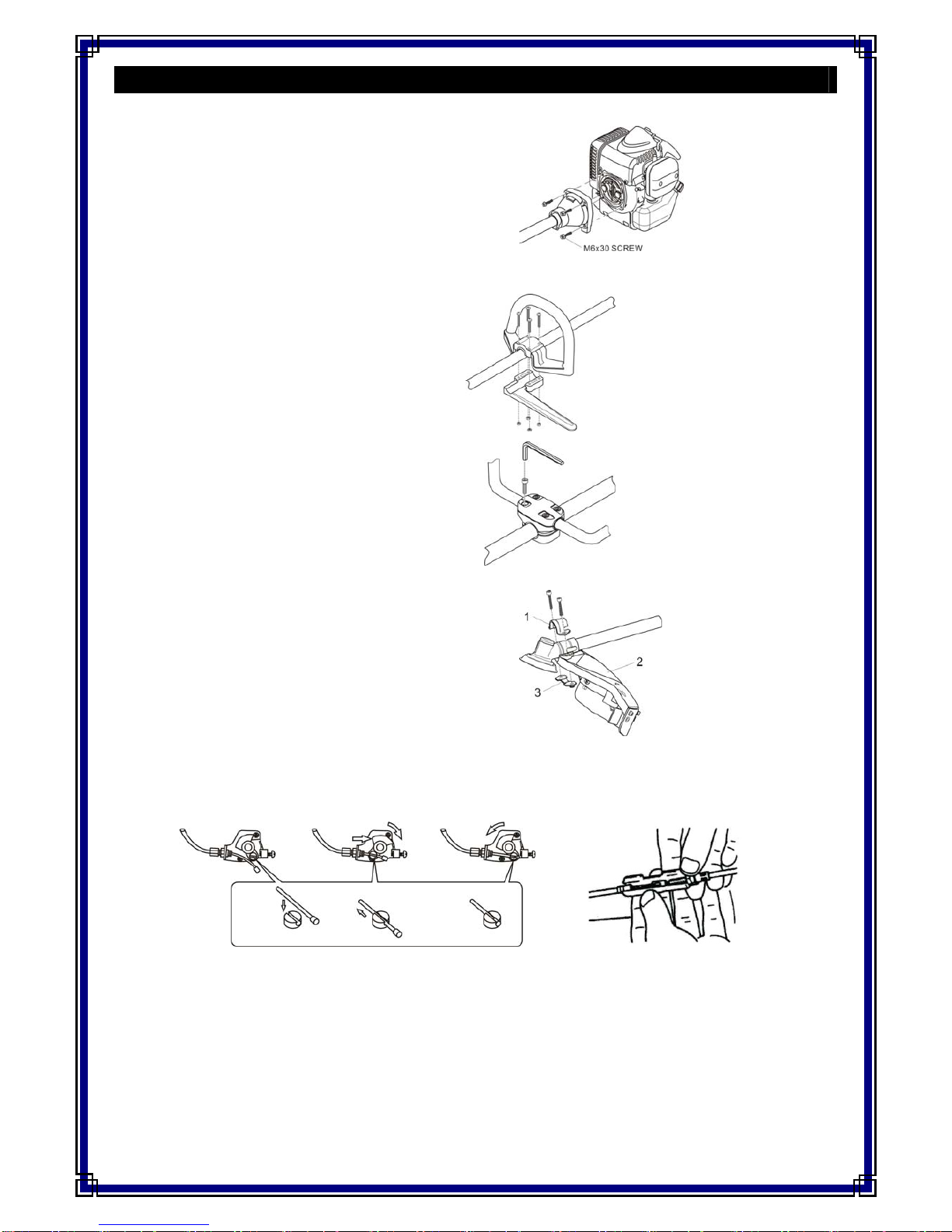
7.ATTACHMENT SETUP
7-1. Attach the Engine to the shaft tube
1. Put engine and shaft tube on the ground then assemble as shown in
Fig.1.
2. Ensure the M6x30 screws are tightened to prevent them coming loose
during operation.
Fig.1
7-2. Handle
D-LOOP HANDLE
1. Adjust the loop handle to the most comfortable position for
the user.
2. Join the loop handle to the main pipe as in Fig. 2-1.
3.Locktightbolts. Fig.2-1
DOUBLE-HAND HANDLES
1. Insert both of the handles into Handle Joint A evenly. Fig.2-2.
2. Adjust the handle joint to the most comfortable position for the
user.
3. Adjust the handles to a suitable angle.
4. Lock tight bolts.
Fig.2-2
7-3. Cutting attachment guard mounting
1. Join the two parts of the cutter guard together using the screws and
nuts supplied.
2. Fit the guard assembly to the drive shaft housing using brackets,
screws and nuts as in Fig 3.
Fig.3
7-4. Throttle wire mounting
1. Pass the throttle wire through the adjusting screw. Fig.4.
2. Move the carburettor swivel toward the attachment.
3. Fit the tip (thick portion) of the throttle wire into the hole in the swivel.
4. Fit the tip of the throttle wire from the throttle trigger into the tip of the throttle wire from the engine. Fig.5.
5. Close the cover so that the arrow mark is set toward the lever by holding the joint of the 2 throttle wires.
Fig. 4 Fig. 5
6

7-5. Lead wire
Connect the 2 lead wires from the throttle trigger to the corresponding 2 wires from the engine as in Fig.6.
Fig.6 Fig.7
7-6. Wearing the double-shoulder harness
Pass your arms through the straps as if putting on a coat. Buckle the harness at the front of your body.
Set the shoulder pads properly. Fig. 7
CAUTION
Only use the quick release mechanism in an emergency!
The double-shoulder harness has a quick release mechanism so that you can release the harness instantly
in an emergency.
1. Pull the harness grip upward to separate the hook from the harness so that the harness is separated from the trimmer.
2. To reconnect the harness to the trimmer, readjust the grip by pulling it and reset the hook ring as in Fig.8-2.
Fig.8-1 Fig.8-2 Fig.8-3
7-7. Cutting attachment mounting.
For the nylon line cutting attachment
1. Match the hole in the side of the cutting attachment guard with the hole in the side of the gear housing.
2. Then insert a 4mm Allen wrench into the holes to stop the clamp moving. Fig. 10
3. Undo the shaft nut by turning in a clockwise direction with the spanner provided.
4. Insert the upper clamp and lower clamp into the gear housing.
5. Rotate the nylon cutting head counterclockwise by hand to attach it to the gear housing.
6. Remove the Allen wrench.
Fig.9 Fig.10
7
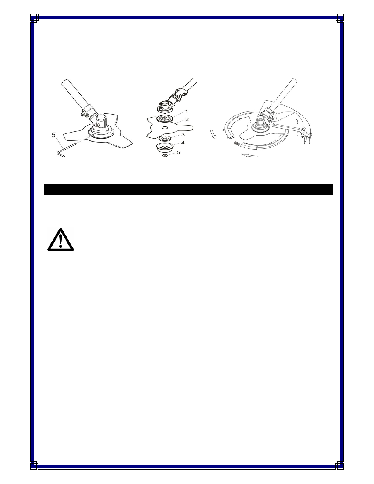
For the blade cutting attachment
1. Match the hole in the side of the cutting attachment guard with the hole in the side of the gear housing.
2. Then insert a 4mm Allen wrench into the holes to stop the clamp moving. Fig.11
3. Undo the shaft nut on the blade cutting attachment head by turning in a clockwise direction with the spanner provided.
4. Remove the blade cutting attachment tightening nut, cup washer and lower blade mounting washer from the gear housing.
5. Fit the cutting blade as in Fig. 12 and tighten the nut securely in an anti-clockwise direction.
6. Remove the 4mm Allen wrench.
7. When not in use store the blade in its protective cover as in Fig. 13.
Fig. 11 Fig. 12 Fig. 13
8. EXAMPLE OF FUEL - MIXING
8-1 Fuel mixing
Use unleaded petrol containing 4%, 2 stroke mineral engine oil (or a ratio of 25:1) or for 2 stroke semi-synthetic or synthetic engine oils
follow the oil manufacturer’s instructions.
WARNING
1. Use a container to mix petrol with 2 stroke engine oil. Do not mix them in the fuel tank directly. Wipe off spilt fuel immediately.
2. Do not use mixed fuel that is older than 30 days as it will deteriorate over time and adversely affect the engine.
3. Do not smoke while mixing fuels.
8
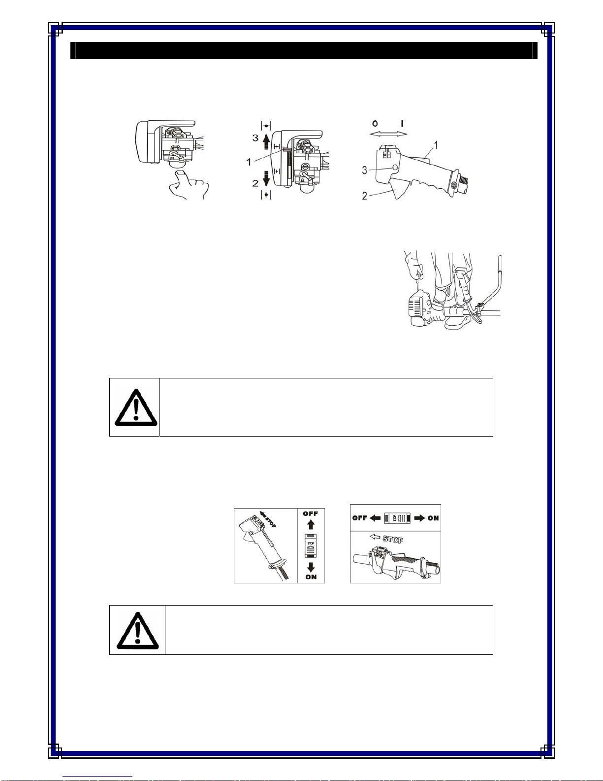
9. STARTING, OPERATION, STOPPING
9-1 Before starting the engine
Check for loose screws and nuts and fill with properly mixed fuel. Place the engine on stable ground with the engine stand (fuel tank) and the
guard resting on the ground.
9-2 To start a cold engine
Fig.14 Fig.15 Fig.16
1. Push the priming pump 5 times. Fig.14.
2. Fully close the choke lever. Fig.15.
3. Set the switch to the Iposition. Fig. 16
4. Hold the trimmer shaft near the engine firmly and as in Fig. 17 pull the starter strongly.
5. When ignition is heard, reset the choke and pull the starter.
6. Warm up the engine for about 3 minutes.
7. When the engine has started at the initial ignition open the choke lever gradually.
9-3 When the engine has been warmed up
1. Fully open the choke lever.
2. Push the priming pump 5 times. Fig.14.
3. Hold the handle and depress the throttle trigger. Release the throttle trigger while
pushing the throttle lock button on the handle. Fig. 17
4. Set the switch to the Iposition. Fig. 16
5. Hold the trimmer shaft near the engine firmly and as in Fig. 17 pull the starter strongly.
6. If the engine does not start, repeat 9-2, the procedure for starting a cold engine.
CAUTION
1. After starting the engine, accelerate and decelerate the engine several times by opening and
closing the throttle trigger.
2. Air in the carburettor causes poor acceleration or engine stoppage.
3. Re-fuel before the fuel is used up. Starting the engine after using all of the fuel is very difficult.
9-4 Operation
After starting the engine, warm it up for about 3 minutes and gradually increase the speed.
9-5 Stopping
Do not suddenly stop the engine when
operating the machine at high speeds.
See Fig. 18 for the Double-Handles or Fig. 18-1
for the D-Loop Handle.
Gradually release the throttle trigger and idle
the engine before setting the switch to STOP.
Fig.18 Fig.18-1
CAUTION
Do not operate the engine at high speeds with no load on the cutting attachment, especially when
the engine is new. When operated at high speeds with no load, it will accelerate to an excessively
high speed that might harm the engine.
9

9-6 When the engine does not start
If the engine does not start or flames flow back through the muffler even though you have pulled the starter many times, remove and check the
spark plug.
1. If the spark plug is dry, no fuel has been fed into the cylinder. Check the fuel pipe and carburettor.
2. Clean or replace the spark plug if they are wet or dirty.
3. If fuel has overflowed into the crank case, remove the spark plug, open the throttle and pull the starter 2 or 3 times
to remove excess fuel from the crank case.
CAUTION
1. Before trimming, check that all the safety devices are attached. The nylon cutting head is fixed securely, the 4mm Allen
wrench has been removed and the nylon cord is the appropriate length.
2. When using the trimmer, be sure to wear goggles, hearing protection and gloves.
10. TRIMMING
1. Wear the harness and hold the brush cutter handle when starting or trimming as in Fig 19 for the Double Handles, or Fig. 19-1 for the
D-Loop Handle.
2. Move the brush cutter attachment from right to left. Be careful of thrown objects. Fig. 20
3. If you have to slant the nylon cutting attachment or blade cutting attachment downward make sure to tilt it towards the cutting side.
Take care not to drag the head on the ground.
4. When using the nylon cutting head the length of the nylon lines will decrease in normal use. To feed more line, with the machine running and
the head rotating, bump the head on the ground as shown in Fig. 21 and the line will automatically increase in length.
Fig.19 Fig.19-1 Fig.20 Fig.21
11. MAINTENANCE
11-1. Cleaning air cleaner
A dirty air cleaner will choke the engine, therefore causing the engine
to stop.
Wash the air cleaner as required.
Replace the cleaner when it becomes dirty.
1. Detach the cleaner mounting screws and remove the cleaner cover.
2. Remove the element.
3. Follow the same procedure as in Fig.22.
Fig.22
CAUTION
The trimmer was designed to cut weeds, grass and similar soft vegetation.
Never use the trimmer for any other applications!
10

Do not store in an enclosure where fuel fumes may accumulate or reach an open flame or spark. Serious
personal injury may result.
11-2. Lubricating the gear housing with grease
The gear housing has a greasing port. Remove the greasing ports screw and feed grease into the port. Grease the port after every 20 hours of
operation. Fig. 23
Fig.23 Fig.24
11-3. Checking the gear housing mounting screws
Loose gear housing fixing screws are very dangerous even though they have covers to prevent them from coming off. Be sure to check them
before operating the trimmer. Tighten the screws securely with the Allen wrench provided with the trimmer.
11-4. Spark plug
The spark plug has a standard electrode-to-electrode distance of 0.6 to 0.7mm Fig.22.
The spark plug electrodes are dry and brown under optimum operating conditions. Clean as necessary.
Use spark plugs designated for the engine.
11-5. Fuel strainer cleaning
The fuel hose has a felt strainer at its end (in the fuel tank) to prevent foreign matter such as sand from entering the carburettor. Clean the strainer
as required because the pump cannot suck up fuel if the strainer is clogged, this would cause the engine to stop. Replace the felt strainer if it is
clogged or damaged.
11-6. Adjusting the throttle cable
Adjust the throttle cable length with the adjusting nut. If the Nylon cutting head rotates even after you have released your hand from the throttle
trigger to idle the engine, adjust the throttle cable length. Loosen the lock nut and turn the adjusting nut to adjust the cable length. Turn the
adjusting nut clockwise to lengthen the throttle and counterclockwise to shorten it. Tighten the lock nut after adjustment.
11-7. Carburettor
11-8.Storing
When shutting down your trimmer for a prolonged period of time (30 days or longer), store it properly, so that it will operate normally when you
need it. The Trimmer may not start smoothly if stored improperly.
1. Store the unit in a dry dust free place, out of the reach of children.
2. Place the stop switch in the “OFF” position.
3. Remove any accumulation of grease, oil, dirt and debris from the exterior of the unit.
4. Perform all periodic lubrication and services that are required.
CAUTION
The engine has been adjusted before shipment. In cases of engine trouble, contact your service
dealer because the engine trouble is not caused by a faulty carburettor alone.An engine that is not
adjusted properly will damage not only the carburettor but also the engine itself.
IMPORTANT
Some tree sap and resins are corrosive. Thoroughly wash the blades after each use, then coat metal parts with light oil.
11

11-9. Storage for engine
1. Drain the fuel tank completely and pull the recoil starter handle several times to remove fuel from the carburettor.
2. Remove the spark plug and pour 7cc (1/4 oz) of fresh, clean, two–stroke engine oil into the cylinder through the spark plug hole.
A. Place a clean cloth over the spark plug hole.
B. Pull the recoil starter handle 2-3 times to distribute the oil inside the engine.
C. Observe the piston location through the spark plug hole. Pull the recoil starter handle slowly until the piston reaches the top of its
travel and leave it there.
3. Install the spark plug (do not connect spark plug cable).
4. Attach the cover to the cutting blades during storage.
MAINTENANCE RECORD
12

12. PARTS DIAGRAMS AND LISTS
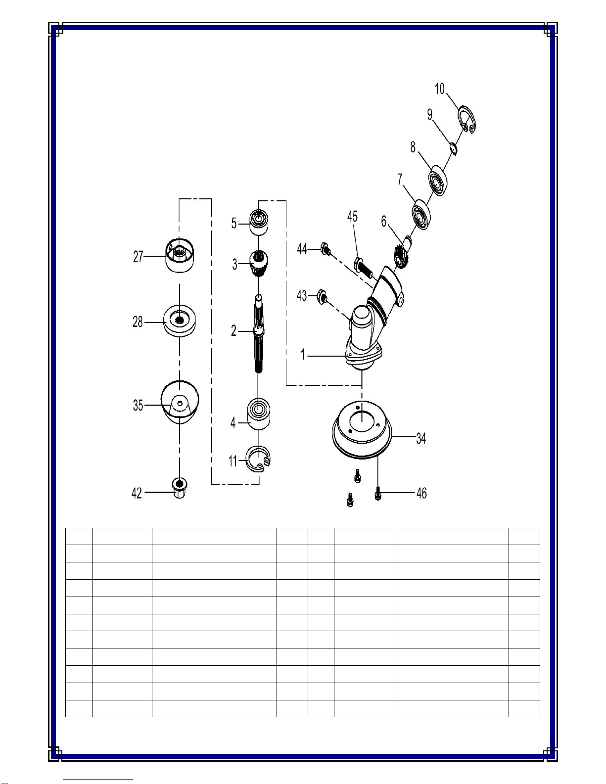
12.1 THPK27L (193826001) – Gear Case
No. Part No. Description No. Part No. Description
1 TH209-1 Gear Case 11 TH209-11 Circlip R28
2 TH209-2 Spline Shaft 39 TH209-39 Hex Bolt M6x8
3 TH209-3 Pinion 40 TH209-40 Hex Bolt M5x10
4 TH209-4 Bearing 6001-2NSE 41 TH209-41 Hex Bolt M6x25
5 TH209-5 Bearing 627(KSK) 28 TH209-28 Inner Blade Washer
6 TH209-6 Gear 29 TH209-29 Outer Blade Washer
7 TH209-7 Bearing 609(KSK) 42 TH209-42 Blade Nut M10
8 TH209-8 Bearing 609Z(KSK) 36 TH209-36 Cover
9 TH209-9 Circlip R-S9 37 TH209-37 Nut Cover
10 TH209-10 Circlip R24 43 TH209-43 Bolt M4x8
13
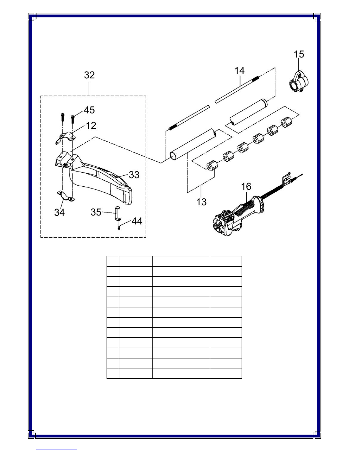
12.2 THPK27L (193826001) – Trigger and Guard
No. Part No. Description QTY
12 TH209-12 Guard Clamp Upper 1
44 TH209-44 Hex Bolt M5x12 1
13 TH208-39 Shaft 1
14 TH208-40 Internal Driveshaft 1
15 TH208-41 Harness Clamp 1
16 TH208-42 Trigger Assembly 1
32 TH209-32 Guard Assembly 1
33 TH209-33 Guard 1
34 TH209-34 Guard Clamp Lower 1
35 TH209-35 Cutter 1
45 TH209-45 Hex Bolt M6x25 2
14
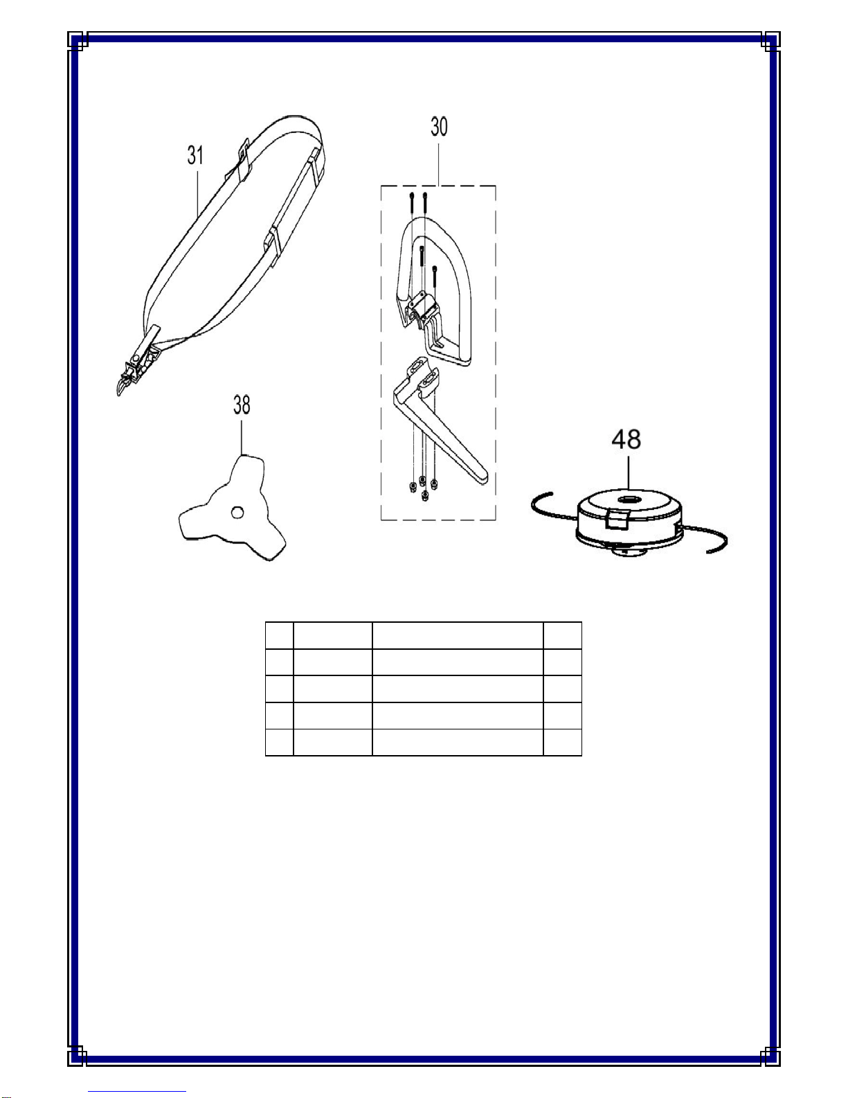
12.3 THPK27L (193826001) – Handle Assembly
No. Part No. Description QTY
30 TH208-54 Loop Handle Assembly 1
31 HP-161 Single Harness Assembly 1
38 WP02641 Blade 1
48 HP-116 Nylon Head 1
15
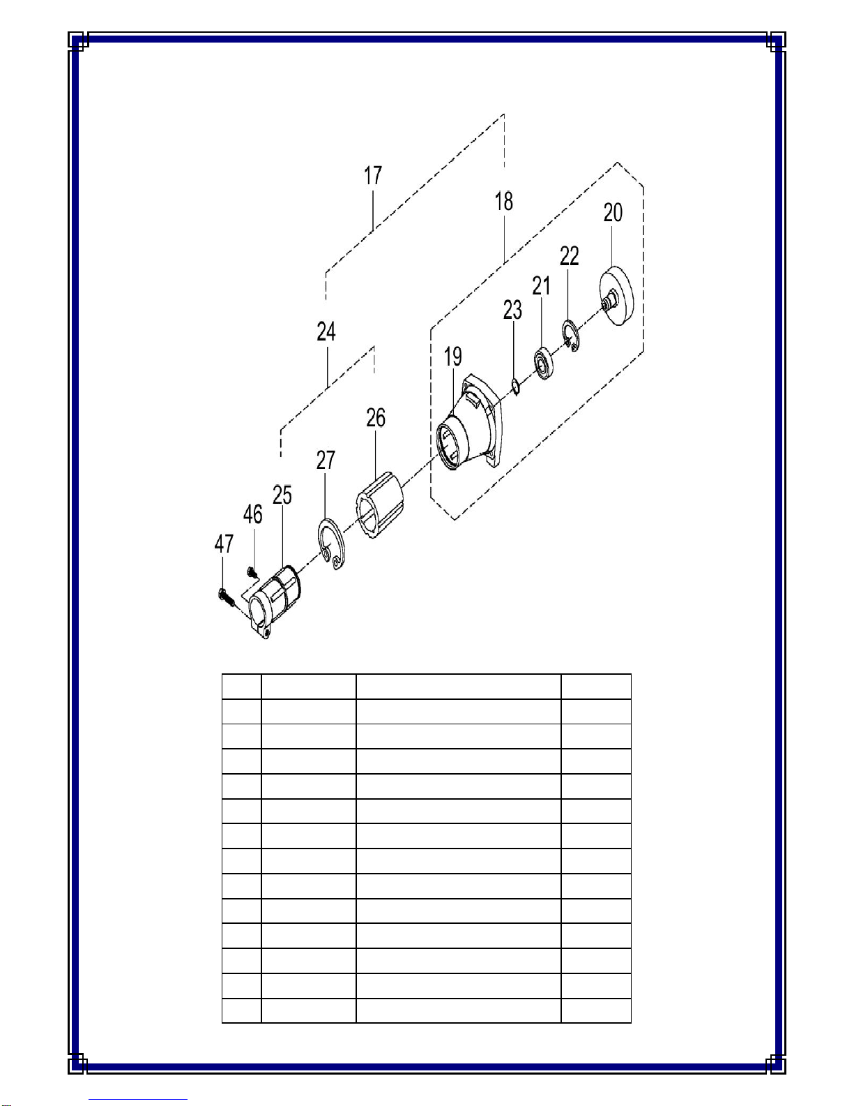
12.4 THPK27L (193826001) – Clutch Assembly
No. Part No. Description QTY
17 TH208-43 Clutch & Boss Assembly 1
18 TH208-44 Clutch 1
19 TH208-45 Clutch Case 1
20 TH208-46 Clutch Drum 1
21 TH208-47 Bearing 6001ZZ 1
22 TH208-48 Circlip R28 1
23 TH208-49 Circlip S12 1
24 TH208-50 Boss Assembly 1
25 TH208-51 Boss 1
26 TH208-52 Rubber Damper 1
27 TH208-53 Circlip R45 1
46 TH208-78 Hex Bolt M5x12 1
47 TH208-79 Hex Bolt M6x28 1
16
12.5 THPK35CH (193827001) - Gear Casing
No. Part No. Description QTY No. Part No. Description QTY
1 TH210-1 Gear Case 1 11 TH210-11 Circlip R32 1
2 TH210-2 Spline Shaft 1 27 TH209-28 Inner Blade Washer 1
3 TH210-3 Pinion 1 28 TH209-29 Outer Blade Washer 1
4 TH209-4 Bearing Z6201-UU 1 34 TH210-34 Cover 1
5 TH210-5 Bearing Z629 1 35 TH210-35 Nut Cover 1
6 TH210-6 Gear 1 42 TH209-42 Blade Nut M10 1
7 TH210-7 Bearing Z6000 1 39 TH209-39 Hex Bolt M6x8 1
8 TH210-8 Bearing Z6000Z 1 40 TH209-40 Hex Bolt M5x10 1
9 TH210-9 Circlip R-S10 1 41 TH209-41 Hex Bolt M6x25 1
10 TH210-10 Circlip R26 1 43 TH209-43 Hex Bolt M4x8 3
17

12.6 THPK35CH (193827001) - Shaft & Guard
No. Part No. Description QTY No. Part No. Description QTY
12 TH210-12 Shaft 1 38 TH210-38 Guard Shield 1
13 TH210-13 Internal Driveshaft 1 39 TH210-39 Guard Clamp Lower 1
15 TH210-15 Harness Clamp 1 40 TH210-40 Guard Clamp Upper 1
16 TH210-16 Circlip R-IR28 1 41 TH210-41 Cutter 1
36 TH210-36 Guard Assembly 1 47 TH209-45 Hex Bolt M6x25 2
37 TH210-37 Guard Top 1
18

12.7 THPK35CH (193827001) – Clutch & Boss
No. Part No. Description QTY No. Part No. Description QTY
17 TH210-17 Boss Assembly 1 23 TH210-23 Bearing Z6202ZZ 1
18 TH210-18 Boss 1 24 TH210-24 Clutch Drum 1
19 TH208-52 Rubber Damper 1 25 TH210-25 Circlip R35 1
20 TH208-53 Circlip R45 1 26 TH210-26 Circlip R-S15 1
21 TH210-21 Clutch Assembly 1 48 TH208-78 Hex Bolt M5x12 1
22 TH210-22 Clutch Case 1 49 TH208-79 Hex Bolt M6x28 1
19
Other manuals for THPK27L
1
This manual suits for next models
1
Table of contents
Other The Handy Brush Cutter manuals


 Technical data")


