The Handy THTPDC Installation and operation manual

OPERATOR’S MANUAL & PARTSLIST
MODEL –THTPDC
650LB TOWED POLY DUMP CART
Spares & Support: 01793 333212
Please read & understand this manual, paying particular attention to the safety
instructions, before use.
The manufacturer reserves the right to change the product specification and
livery according to continued product improvements.
193845001 15/06/2015


Assembly Is Required
This product requires assembly before use. See the “Assembly” section for instructions. Because
of the weight and size of the Trailer, it is recommended that a minimum of TWO adults be
present to assist with the assembly.
CONTENTS
SPECIFICATIONS
SAFETY INSTRUCTIONS
OPERATING INSTRUCTIONS
MAINTENANCE & STORAGE
ASSEMBLY
PARTS DIAGRAM & LIST
GUARANTEE
NOTES

SPECIFICATIONS
Model
THTPDC
Product Number
193845001
Load Capacity
650lb (295kg)
Bed Dimensions (mm)
(L)1025 x (W)765 x (H)275
Overall Dimensions (mm)
(L)1550 x (W)870 x (H)690
Tyre Size
407mm (16”)
Tyre Type
Pneumatic
Tyre PSI (Recommended/Maximum)
20 PSI/25 PSI (Do not exceed)
Weight
25kg
The manufacturer reserves the right to change the product specification and livery according to
continued product improvements.

SAFETY INSTRUCTIONS
Read and understand the owner’s manual and labels affixed to the machine. Learn its application
and limitations as well as the specific potential hazards. Retain these instructions for future
reference. The operator is responsible for following the warnings & instructions in this manual and
on the product.
During Operation
•
Do not at any time allow anyone to sit or stand on the Trailer.
•
Do not allow children to play on, stand upon or climb in the Trailer.
•
Always inspect the Trailer before use to ensure it is in good working condition.
•
Immediately replace or repair damaged or worn parts before using the Trailer.
•
Always check and tighten hardware and assembled parts before operation.
•
Do not exceed the equipment maximum load capacity of 650lb (295kg).
•
Do not try to carry loads that make the truck unstable.
•
Avoid large holes and ditches when using the Trailer.
•
Be careful when operating on steep gradients (hills) the Trailer may tip over.
•
Always operate at a reduced speed in rough terrain, along creeks, ditches and on hillsides.
•
Do not operate close to creeks, ditches and public roads.
•
To avoid personal injury and/or equipment damage DO NOT EXCEED 10 MPH.
•
Always use caution when loading and unloading the Trailer.
•
Only tow with recommended vehicles (Lawn/Garden Tractors and ATVs).
•
Always secure and lock the Towed Trailer to the vehicle hitch before operating.
•
Check and inflate the tyres. We recommend the use of FOOT or HAND inflation devices only.
Recommended pressure is 20PSI. Do not inflate above 25psi.
Crush and Cut Hazards
•
Always keep your hands and feet clear from moving parts while operating the equipment.
•
Always keep the work area clean and clear when operating.
•
Always wear safety gear, eye protection, gloves and work boots when operating the Trailer.
Safety alert symbol. Used to alert you to potential personal injury hazards. Obey all safety
messages that follow this symbol to avoid possible injury.
DANGER - Indicates an imminently hazardous situation which, if not avoided, will result in
serious injury.
WARNING - Indicates a potentially hazardous situation which, if not avoided, could result in
serious injury
CAUTION - Indicates a potentially hazardous situation which, if not avoided, may result in
minor or moderate injury.
CAUTION
Used without the safety alert symbol indicates a potentially hazardous situation which, if not
avoided, may result in property damage.

OPERATING INSTRUCTIONS
WARNING –Before using the Trailer, review the below instructions & safety information
within the manual. Failure to follow these instructions may result in property damage or injury to
the operator or bystanders.
1. DO NOT at any time carry passengers.
2. DO NOT exceed the rated capacity of 650lb (295kg).
3. ALWAYS secure and lock the Trailer to the vehicle hitch before operating.
4. ONLY use approved vehicles when towing the Trailer (Lawn/Garden Tractors and ATVs)
5. NEVER tow the Trailer with the box raised.
6. DO NOT over fill the Trailer. This could cause the Trailer and towing vehicle to lose traction and
skid out of control.
7. ONLY fill the Trailer to a manageable dumping load. Extremely heavy loads will be difficult to
operate the tipping mechanism.
8. ONLY use the Trailer for its intended purpose.
9. ALWAYS make sure that the combined weight of the tow vehicle and the operator is greater than
the load of the Trailer. If the Trailer is heavier it may be difficult to control.
10. DO NOT use the Trailer on public roads.
11. NEVER exceed 10mph when towing the Trailer.
12. DO NOT make sharp turns as this may cause the Lawn/Garden Tractor or ATV tyres to rub against the
Towed Trailer.
13. ALWAYS slow down before turning.
14. ALWAYS use caution when reversing the Trailer. To avoid the Trailer “jack-knifing” always reverse in
a straight line.
CAUTION –To avoid possible injury, be sure that no bystander is near the cart before
releasing the latch.
TOW CART
To convert the cart for towing, remove the plastic cap from the draw bar. Remove the Ø13x98 clevis
pin and R Pin which secure draw bar A in the storage position underneath draw bar B. Pivot draw bar
A outward and secure it in the towing position using the same clevis pin and hairpin cotter. Pushthe
handle in all the way against the front of the tray depressing the buttons in the bottom of the handle.
Always test to make sure your tractor has adequate towing and braking capabilities whenever hauling
a substantial amount of weight in your cart. Use extra caution when operating on slopes.
Do Not Exceed the 650 LB. (295kg) weight capacity of the cart.
CAUTION –Vehicle braking & stability may be affected by the cart. Be aware of changing
conditions on slopes
Distribute the weight of the load evenly in the cart to improve handling and traction.
Todump material from the cart, remove the clevis pin Ø13x28 from the latch on the draw bar and
release the latch. The cart bed will then tilt backwards to empty its contents. After emptying, pull the
front of the bed down toward the cart draw bar until the latch snaps into place. Reinstall the clevis pin
in the latch to prevent accidental release.
The maximum towing speed for this cart is 10 m.p.h.

PUSH CART
Important: Leave the latch lock clevis pin in place at all times while using the cart as a push cart.
To convert the cart for push operation, remove the Ø13x98 long clevis pin and R Pin Ø3 which secure
the draw bar in the towing position. Pivot draw bar A into the storage position underneath draw bar B
and secure it using the Ø13x98 long clevis pin and R Pin Ø3.
Distribute the weight of the load evenly in the cart to improve handling and help prevent accidental
tipping.
Do not load more weight into the push cart than you can physically handle and control comfortably.
To dump material from the push cart, lift up on the handle and tilt the cart backwards. Be sure that the
latch mechanism on the draw bar is locked and secured with the clevis pin to prevent accidental
release of the latch.
MAINTENANCE & STORAGE
WARNING - Improper maintenance & storage of the Trailer may void your warranty.
MAINTENANCE
After each use clean any material out of the Trailer.
Rinse/dry inside and outside of the Trailer after each use.
Before operating make sure the tyres have the recommended tyre pressure of 20 PSI (Do not exceed
25PSI). We recommend the use of FOOT or HAND inflation devices only.
Grease the axle and the wheel bearing area regularly with Multi-purpose grease.
Periodically check all nuts & bolts for tightness.
Annually clean and lightly lubricate parts including the latch, pivot bolt and the area of the axle
where the draw bar pivots, with Maintenance spray.
Use a glossy enamel spray paint to touch up scratched or worn painted metal surfaces.
Never exceed the load capacity rating of 650lb (295kg) this will damage the Trailer.
IMPORTANT:
Only use the manufacturer’s original replacement parts. Non-original replacement parts will
invalidate
your warranty and may result in a safety hazard or poor operation. Parts are available by
calling 01793 333212.
STORAGE
Never allow material to remain in the Trailer for extended periods of time.
For years of trouble free service, make sure the Trailer is clean and dry before storing.
Store indoors or in a protected area during severe weather and winter months.
When storing outside always keep the draw bar a little higher than the back of the Trailer to allow
any moisture to run out of the back and not to accumulate in the carry area.

ASSEMBLY
Remove the hardware pack and all loose parts from the carton. Be sure the carton is empty before
discarding.
Insert the latch lock between the latch mount brackets and connect them using an M6x20 hex bolt
and a M6 lock nut. Tighten so that the latch lock can still pivot. Attach the extension spring to the
latch lock and the latch mount bracket as shown in figure 1.
Insert the Ø13x28 clevis pin through the holes in the latch mount brackets and secure with an
Ø3 R-pin.
Attach the latch lock assembly to draw bar B using two M6x16 hex bolts and M6 lock nuts & tighten
securely.
Draw Bar B

Lay draw bar B (open side facing up) onto the Wheel Support. Insert the axle through the wheel
support and draw bar B.
Connect the hitch bracket to draw bar A, using two M8x20 hex bolts and M8 lock nuts. Tighten.
Attach the leg stand bracket to draw bar A, using a M8x20 hex bolt & M8 lock nut. Tighten.
Draw Bar B
Draw Bar A
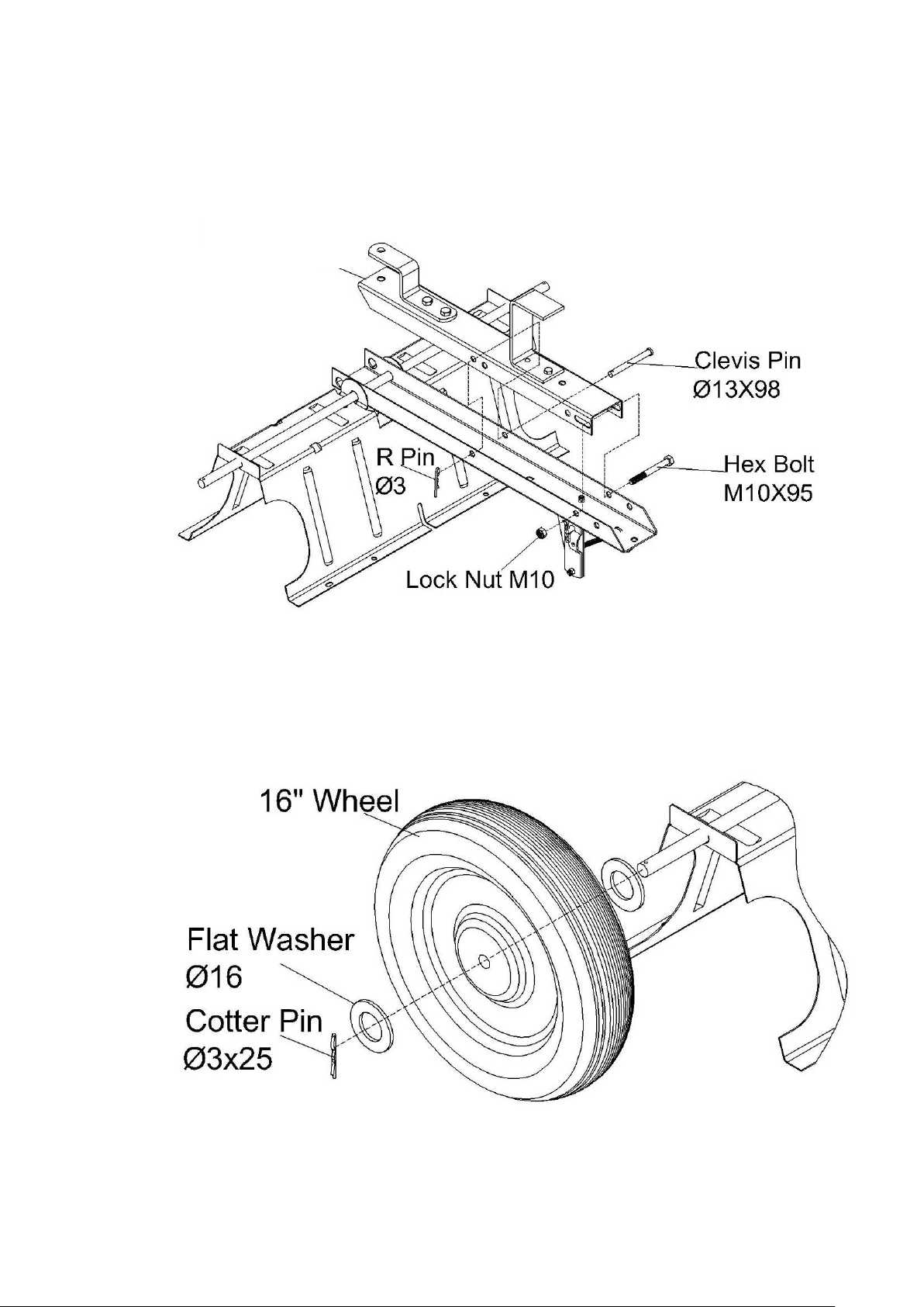
Place draw bar A, inside draw bar B as shown below. Fasten the draw bar sections together using an
M10x95 hex bolt and a M10 lock nut. Tighten, leaving the nut just loose enough that the sections of
the draw bar can pivot freely.
Insert clevis pin Ø13x98 through both parts of the draw bar and secure with an R Pin Ø3.
Place Flat Washer Ø16 onto the Axle, followed by the wheel, ensuring the inflation valve is facing
away from the assembly. Add a second Flat Washer Ø16 before inserting Cotter Pin Ø3x25through
the axle.
Repeat the same actions on the opposite side.
Draw Bar A

Turn the wheel support over to rest on the wheels. Place the Latch Stand Bracket onto the draw bar,
sliding it underneath the Latch Lock. Place the Latch Stand Plate on top of the latch stand bracket.
The tabs at the ends of the channels must face the rear.
Place the poly tray down onto the Wheel Support & the Latch Stand Plate. Fasten the tray to the
wheel support using eight M8x16 flat head bolts and M8 lock nuts. Fasten the tray to the Latch Stand
Plate & Latch Stand Bracket using four M6x16 Flat head bolts and M6 lock nuts. Ensure finger tight
only.
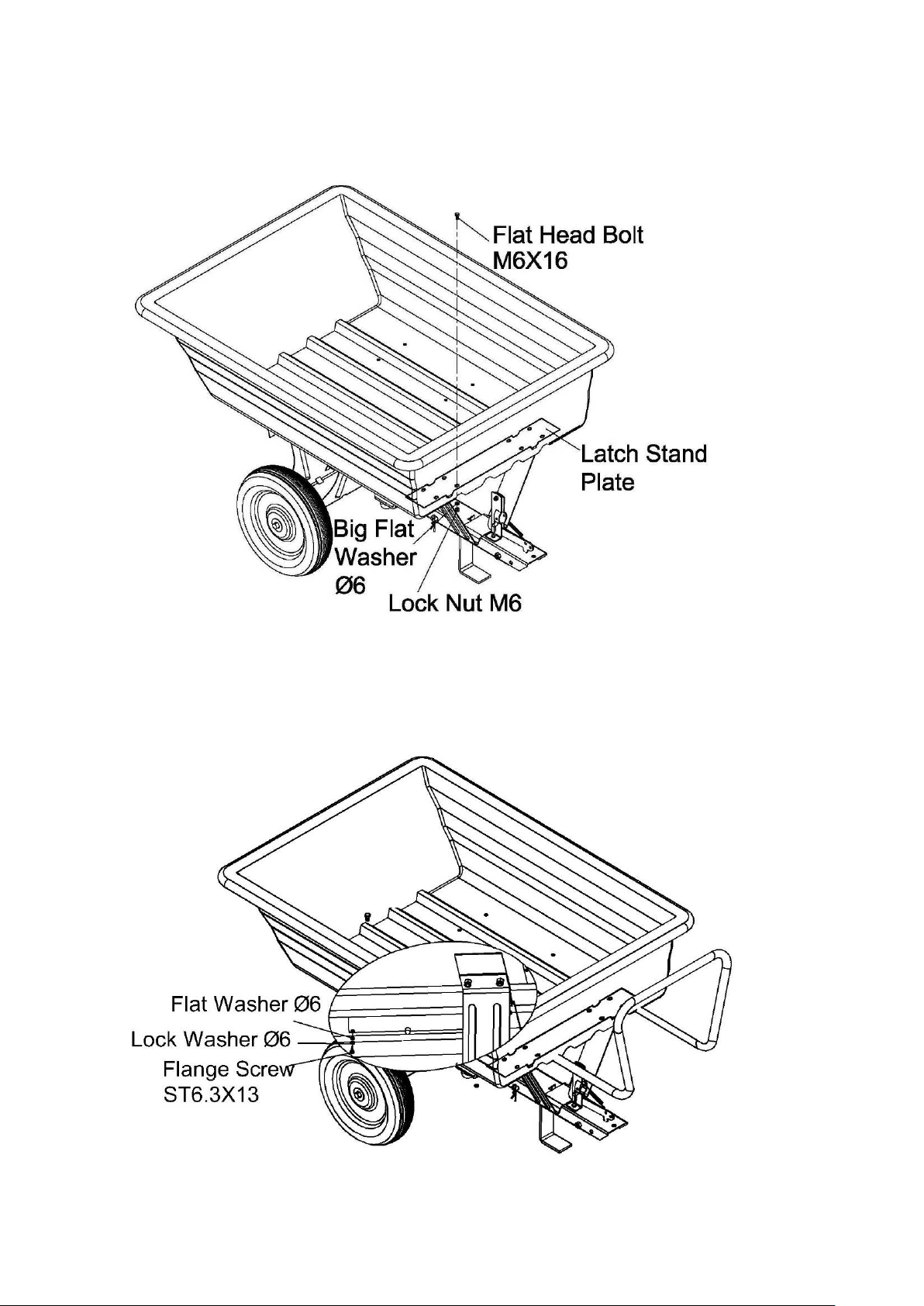
Insert four flat head bolts M6x16 down through the tray and the inner holes in the Latch Stand Plate.
Secure the bolts with four Ø6 big flat washers and M6 lock nuts. Do not fully tighten.
Slide the handle into the channels in the Latch Stand Plate. Push the handle in all the way against the
front of the tray depressing buttons in the bottom of the handle.
Place an Ø6 lock washer and a Ø6 flat washer onto each of the two ST6.3x13 flange screws. Insert
the
screws into the small holes at each end of the handle.

Rotate the Draw Bar A from underneath Draw Bar B, to the below extended Draw Bar image and
secure with Clevis Pin’s Ø13X28 & Ø13X98 and Hex Bolt M10x20.
Insert the hitch pin through the draw bar and hitch bracket and secure it with the Ø3 R Pin.
Hex Bolt M10x20

PARTS DIAGRAM

PARTS LIST
ITEM NO
PART NO
DESCRIPTION
QTY
ITEM NO
PART NO
DESCRIPTION
QTY
1
TH180-1
Poly Tray
1
19
TH180-19
Hex Bolt M6x20
1
2
TH180-2
Flat Head Bolt M8x16
8
20
TH180-20
Latch Mount Bracket (Right)
1
3
TH180-3
Flat Head Bolt M6x16
8
21
TH180-21
Latch Lock
1
4
TH180-4
Flat Washer Ø6
2
22
TH180-22
Lock Washer Ø6
2
5
TH180-5
Latch Stand Plate
1
23
TH180-23
R Pin Ø3
3
6
TH180-6
Lock Nut M6
11
24
TH180-24
Extension Spring
1
7
TH180-7
Flange Screw ST6.3x13
2
25
TH180-25
Hex Bolt M10x20
1
8
TH180-8
Pin
2
26
TH180-26
Lock Nut M10
2
9
TH180-9
Latch Stand Bracket
1
27
TH180-27
Clevis Pin Ø13x98
1
10
TH180-10
Lock Nut M8
12
28
TH180-28
Hex Bolt M10x95
1
11
TH180-11
Wheel Support
1
29
TH180-29
Leg Stand Bracket
1
12
TH180-12
Axle
1
30
TH180-30
Hex Bolt M8x20
4
13
TH180-13
Flat Washer Ø16
4
31
TH180-31
Hitch Pin
1
14
TH180-14
Wheel
2
32
TH180-32
Hitch Bracket
1
15
TH180-15
Cotter Pin Ø3x25
2
33
TH180-33
Draw Bar A
1
16
TH180-16
Draw Bar B
1
34
TH180-34
Handle
1
17
TH180-17
Clevis Pin Ø13x28
1
35
TH180-35
Latch Mount Bracket (Left)
1
18
TH180-18
Hex Bolt M6x16
2
36
TH180-36
Big flat Washer Ø6
4

GJ HANDY & CO LTD USER WARRANTY POLICY
1. Users Statement of Warranty
Each new machine is warranted against defective material or assembly of material under normal
usage. The warranty applies to the original purchaser and covers faulty parts and the labour involved
in replacing and repairing those parts, which are of original manufacture.
2. Period of Warranty
All Webb, Handy Pro (Brushcutter & Long Handle Hedgecutter only) and Sanli domestic products
2 years from the original date of sale to the first domestic user.
90 days from the original date of sale to the professional/commercial user.
90 days from the original date of sale when used for hire.
Engines as per the manufacturer’s warranty statement which will be supplied with the machine.
1 year from the original date of purchase for Replacement Spare Parts (unless normal wear & tear
component, which are covered for 90 days).
All machines’ must be serviced within the first 12 months from the original date of purchase to
comply with the warranty, failure to do so will invalidate the 2nd year of the warranty.
A reduced warranty period of ninety days applies to those items which are subject to normal wear
and tear (e.g. wheels, tyres, cutter bars, cylinders, bottom blades, belts, cables, grass bags, spark
plugs).
All Handy, Handy Pro (All others), Mowerland and Q-Garden domestic products
1 year from the original date of sale to the first domestic user.
90 days from the original date of sale to the professional/commercial user.
90 days from the original date of sale when used for hire.
Engines as per the manufacturer’s warranty statement which will be supplied with the machine.
1 year from the original date of purchase for Replacement Spare Parts (unless normal wear & tear
component, which are covered for 90 days).
A reduced warranty period of ninety days applies to those items which are subject to normal wear
and tear (e.g. wheels, tyres, cutter bars, cylinders, bottom blades, belts, cables, collection bags,
spark plugs).
All warranty repairs must be undertaken by an authorised service dealer.
These dealers have been accredited by GJ Handy & Co Ltd and agree to only use genuine parts and
follow our repair procedures.
Version 2 06-15

GJ HANDY & CO LTD USER WARRANTY POLICY
3. Not covered by this warranty
The warranty policy does not cover any depreciation or damages caused by ordinary wear, rusting or
corrosion, lack of correct maintenance or operation, misuse, abuse, lack of transportation or
accident.
The warranty policy does not cover any costs necessary for the standard periodic maintenance
services instructed by the operators manual, or service parts replacement which would include oil,
filters, tyres, belts, brake linings, fuses, blades, seals and other service parts unless it can be proven
that the item has evidence of faulty manufacture.
The warranty policy will not cover failure or damage caused as a result of parts or accessories being
modified without the written approval of GJ Handy & Co Ltd.
The warranty policy will not cover the unit if non-genuine parts have been fitted and as a result
damage has occurred to the unit.
The warranty policy is non transferable and is only applicable to the original purchaser.
4. Disclaimer
This warranty is only a remedy for defect of products. GJ Handy & Co Ltd will never warranty in
terms of the merchantability or the fitness for a particular purpose.
No person is authorised to make any warranties, representations or promises, expressed or implied,
on behalf of GJ Handy & Co Ltd, or to modify the terms conditions or limitation of this warranty
policy in any way.
Neither GJ Handy & Co Ltd nor any company affiliated with GJ Handy & Co Ltd shall be liable in any
event or manner whatsoever for incidental or consequential damages or injuries, including, but not
limited to, loss of crops, loss of profit, out of pocket expenses or profits, rental of substitute
equipment or other commercial losses.
5. General
Most warrantable failures show up within the first few weeks of use. These failures are usually
straightforward and warranty assessment is relatively easy.
Failures relating to cutter decks and belts need careful investigation, as the cause may not always be
straightforward. Look for damage to blades and pulleys especially when the cutter belt or blade boss
have snapped or cracked as this could be due to impact damage.
Customers should always refer to the operator/instruction manual when any disputed problem
arises, you will find most areas covered within the manual.
Version 2 06-15

NOTES
__________________________________________
__________________________________________
__________________________________________
__________________________________________
__________________________________________
__________________________________________
__________________________________________
__________________________________________
__________________________________________
__________________________________________
__________________________________________
__________________________________________
__________________________________________
__________________________________________
__________________________________________
__________________________________________
__________________________________________
__________________________________________
__________________________________________
__________________________________________
__________________________________________
__________________________________________
__________________________________________
__________________________________________
__________________________________________
__________________________________________
__________________________________________


Toorder spare parts and see the complete range of garden machinery and
garden equipment from Handy, visit:
www.thehandy.co.uk
Spares & Support: 01793 333212
This symbol on the product or on its packaging indicates that this product may not be treated as household waste. Instead
it shall be handed over to the applicable collection point for the recycling of electrical and electronic equipment.
For more detailed information about recycling of this product, please contact your local council office, your household
waste disposal service or shop where you purchased the product.
Other manuals for THTPDC
1
This manual suits for next models
1
Table of contents
Other The Handy Outdoor Cart manuals


