The Handy THHC30SB Installation and maintenance instructions

Page 1
OPERATOR’S MANUAL AND PARTS LIST
PETROL HEDGE TRIMMER - THHC30SB
Spares & Support 01793 333212
www.thehandy.co.uk
Before use please read & understand this manual, paying particular
attention to the safety instructions.
02/03/2011

Page 2
CONTENTS
SAFETY INSTRUCTIONS 3
SPECIFICATIONS 4
MAJOR PARTS 4
FUEL 5
OPERATION 6
HINTS AND TIPS 7
MAINTENANCE 8-9
PARTS DIAGRAMS 10-13
EC DECLARATION OF CONFORMITY 14

Page 3
SAFETY INSTRUCTIONS
Read and understand the owner’s manual and labels afxed to the hedge
trimmer. Learn its application and limitations as well as the specic potential
hazards. Retain these instructions for reference.
• Use sturdy footwear and a helmet with eye and ear protection.
Protect exposed parts of your body. Wear heavy duty gloves, preferably
made of leather.
• Do NOT operate the hedge trimmer if you are tired, ill or under the inuence
of alcohol or drugs.
• Do NOT smoke when using the hedge trimmer and ensure caution when
handling fuel. We recommend you fuel the machine at least 3m away from
where you wish to work in case any spilt fuel ignites when starting the engine.
• Ensure that bystanders, children and pets keep well away when starting or
cutting - at least 15m.
• Inspect the hedge trimmer, and in particular the cutter blade, before use
for any worn or damaged parts. Do not use until the parts are repaired or
replaced.
• Before starting the engine make sure the cutter blade is not in contact with
anything and have a clear work area and secure footing.
• Hold the hedge trimmer rmly with both hands when using and keep all parts
of your body away from the machine. Always ensure a safe rm footing and
do not over-reach.
• Always carry the hedge trimmer with the engine stopped and the cutter blade
covered.
• Never lay the hot hedge trimmer down on dry grass or any combustible
material where there is a re risk from the hot engine.
• Only use the hedge trimmer in good light and visibility. During cold weather be
aware of slippery or wet areas.
• NEVER operate the hedge trimmer in a tree or from a ladder.
• NEVER feed twigs or other material to be cut into the cutter blade with your
hands. Do not lift the hedge trimmer by the cutter blades and be aware that
the blades may run on after the engine has stopped.
• Please recycle the cardboard packaging in which the hedge trimmer is
delivered.
Always shut off the engine before setting it down.
Page 4
SPECIFICATIONS
Model No THHC30SB
Weight (with blade cover) 5.3kg
Fuel Tank Capacity 600 ml
Engine Displacement 22.5 cm³
Cutting Length 690 mm
Maximum Engine Performance 0.65 Kw
Maximum Blade Speed 1.53 m/s
Idling Speed 3000 per min
Clutch Engagement Speed 3800 per min
Carburettor Type Ruixin/huayi
Ignition System Hic
Spark Plug BPM6A
Electrode Gap 0.6~0.7
Mixture Ratio 25:1 mineral oil, for synthetic see below
Gear Ratio 14:58
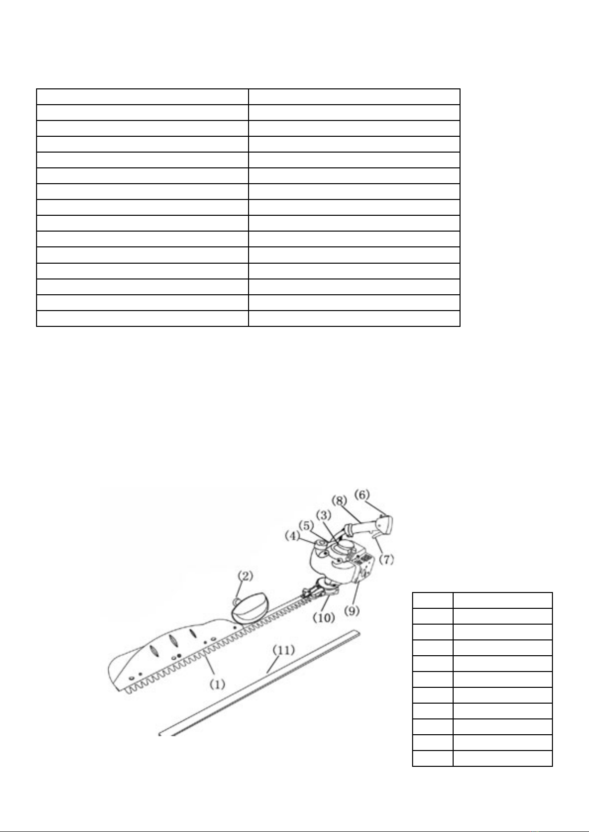
MAJOR PARTS
1 Blade
2 Front Handle
3 Recoil Starter
4 Fuel Tank Cap
5 Carburettor
6 On/Off Switch
7 Throttle Lever
8 Rear Handle
9Mufer
10 Gearbox
11 Blade Cover

Page 5
FUEL
Petrol is very ammable. Avoid smoking or fuelling the chainsaw
anywhere near a ame or sparks. Allow the engine to cool before
re-fuelling. Fuel the engine at least 3m away from your work area.
• Use a ratio of 25:1 unleaded petrol to 2-stroke mineral oil.For semi-synthetic or
semi-synthetic use the manufacturer's ratio. Mix in the mixing bottle provided.
• Unscrew the fuel cap, and fuel the machine to 80% capacity. Fasten the fuel
cap tightly and wipe up any spillage.
• Ensure that any stored petrol/oil mixture (2-stroke) is clearly marked in a
separate can and only stored for 4-6 weeks. If the hedge trimmer is not going
to be used for a long period, drain the mixture from the fuel tank, start the
engine and drain the carburettor of any remaining fuel.
• Dispose of any unwanted 2-stroke mixture at an authorised recycling point.
Attaching the Rear Handle:
• Attach the rear handle using the two nuts and bolts supplied.
• Undo the two bolts, t the handle into the xed “U” shaped bracket.
• Place the other bracket on top and tighten the two nuts and bolts.

Page 6
OPERATION
Before use, check that the cutter blade is not damaged, the handles and
controls are easy to use and that the STOP On/Off switch operates correctly.
The idling speed should be set so that the blades do not move whilst the
engine is idling.
1. Push the STOP switch to “I” position.
2. Squeeze lock lever A and then the throttle lever B.
3. Keeping throttle lever B depressed, press throttle lock C inward.
4. Keeping throttle lock C depressed, release throttle lever B - this will lock
throttle lever B in position.
5. Gently depress the primer pump 7-10 times until fuel comes into the primer
pump.
6. Move the choke lever to ‘open’.
7. Holding the unit down rmly, slowly pull the starter cord until resistance is
felt and continue with a sharp pull until the engine res.
8. Move the choke lever to ‘closed’ and pull the starter cord again until the
engine res.
9. As soon as the engine starts, squeeze and release the throttle, this
releases the throttle lever B so that the engine can idle.
10. Run the engine for approximately one minute at moderate speed before
applying full speed.
• If starting a warm engine, try procedures 1, 7 and 8. If the engine does not
start repeat the whole procedure from step 1.
To Stop the Machine:
• Release the throttle lever completely and push the STOP switch to the “O”
position.

Page 7
Always hold the hedge trimmer rmly with both hands when using.
Before cutting ensure that the blades are running at full speed and be aware that
the blades may keep moving after you have released the throttle.
It is advisable to cut a hedge from the bottom up sweeping the cutter bar in an arc
as you move along the hedge.
To cut the top of the hedge, hold the cutter bar at an angle of 0-10 degrees as you
swing the hedge trimmer horizontally. Sweep the cutter bar in an arc towards the
outside of the hedge so that the cuttings are swept onto the ground.
Pay special attention when cutting hedges along a wire fence. The blades may be
damaged if they come into contact with the wire.
Do not use the hedge trimmer for long periods of time - take a break of 10-15
mins after every 50 mins of use or after using one tank of fuel.
If the blades hit a stone, wire or other foreign object, turn off the engine and check
for any damage. Replace any damaged blades before continuing.
Do not attempt to remove any twigs or branches jammed in the cutter blades
without rst turning the machine off.
HINTS AND TIPS
Page 8
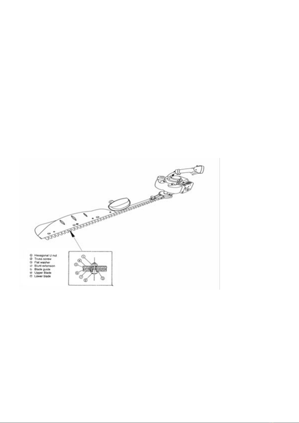
MAINTENANCE
To ensure a long service life and to avoid any damage to the hedge trimmer
perform the following maintenance at regular intervals.
Blade Adjustment:
After a period of time the blades may need adjusting.
Refer to the diagram below and follow these guidelines:
1. Loosen nut 1.
2. Turn screw 2lightly until it stops turning and the turn back ¼ -½ turn.
3. Tighten nut 1whilst holding screw 2.
4. Lubricate the blades with light oil after adjustments.
5. Start the engine and operate throttle on and off for a minute making sure the
blades run freely.

Page 9
STORAGE
When storing the hedge trimmer for any length of time it is important to drain the
fuel, both in the tank and the carburettor. Either drain the fuel manually or run the
engine until it uses up all the fuel.
Remove the spark plug and add a few drops of oil into the spark plug hole.
Pull the starter cord gently to conrm that a lm of oil covers the engine inside.
Tighten the spark plug.
Clean dirt or dust from the cutter blade and the outside of the machine and wipe
with an oily cloth.
Store in a dry place.
Air Filter:
Check and clean the Air Filter regularly to ensure optimum performance.
Remove the air lter cover, take out the sponge element and wash it in lukewarm
water. Allow it to dry completely before putting it back in the Air Filter. Clean off
any excessive dirt and dust.
Spark Plug:
Check the spark plug periodically and ensure that the gap between the electrodes
is between 0.6 and 0.7mm. Adjust where necessary using the universal wrench
supplied. If the spark plug is clogged with carbon, clean thoroughly or replace.
Grease:
Supply good quality grease to the gear case through the grease hole for every 10
to 20 hours of operation.

Page 10
PARTS - ENGINE

Page 11
PARTS - ENGINE
No Part No Desc Qty No Part No Desc Qty No Part No Desc Qty
1 TH118-1 Cylinder 1 2 TH118-2 Gasket, base 1 3 TH118-3 Bolt M5x22 2
4 TH118-4 Insulator 1 5 TH118-5 Gasket, insula-
tor 1 6 TH118-6 Gasket, carb 1
7 TH118-7 Screw M5x20 2 8 TH118-8 Mufer Assy 1 9 TH118-9 Mufer 1
10 TH118-10 Spark Arrester 1 11 TH118-11 Bolt M5x50 2 12 TH118-12 Gasket, mufer 1
13 TH118-13 Plate, mufer 1 14 TH118-14 Screw M4x16 1 15 TH118-15 Crankcase,
comp 1
16 TH118-16 Gasket, case 1 17 TH118-17 Bearing 2 18 TH118-18 Oil Seal 1
19 TH118-19 Oil Seal 1 20 TH118-20 Snap Ring 1 21 TH118-21 Bolt M5x30 4
22 TH118-22 Guard 1 23 TH118-23 Screw M5x14 1 24 TH118-24 Piston 1
25 TH118-25 Ring, piston 2 26 TH118-26 Pin, piston 1 27 TH118-27 Snap Ring 2
28 TH118-28 Bearing 1 29 TH118-29 Washer 2 30 TH118-30 Crankshaft
comp 1
31 TH118-31 Nut 1 32 TH118-32 Key 1 33 TH118-33 Shoe 2
34 TH118-34 Screw 2 35 TH118-35 Spring 1 36 TH118-36 Washer 2
37 TH118-37 Washer 2 38 TH118-38 Case, clutch 1 39 TH118-39 Screw M5x16 4
40 TH118-40 Plate, clutch 1 41 TH118-41 Nut 1 42 TH118-42 Rotor 1
43 TH118-43 Coil Assy 1 44 TH118-44 Cord 1 45 TH118-45 Cap 1
46 TH118-46 Cap, spark plug 1 47 TH118-47 Spring 1 48 TH118-48 Grommet 1
49 TH118-49 Spacer 2 50 TH118-50 Bolt M4x25 2 51 TH118-51 Recoil Assy 1
52 TH118-52 Case, recoil 1 53 TH118-53 Spring, spiral 1 54 TH118-54 Reel 1
55 TH118-55 Ratchet 1 56 TH118-56 Spring 1 57 TH118-57 Screw 1
58 TH118-58 Retainer 1 59 TH118-59 Washer 1 60 TH118-60 Rope 1
61 TH118-61 Knob 1 62 TH118-62 Screw 4 63 TH118-63 Bracket 1
64 TH118-64 Gasket, carb 1 65 TH118-65 Carburettor
Assy 1 66 TH118-66 Screw 1
67 TH118-67 Ring 1 68 TH118-68 Swivel 1 69 TH118-69 Valve Assy 1
70 TH118-70 O-Ring 1 71 TH118-71 Jet No 37 1 72 TH118-72 Rebuild Kit 1
73 TH118-73 Body Assy 1 74 TH118-74 Screen 1 75 TH118-75 Gasket Kit 1
76 TH118-76 Diaphragm, pump 1 77 TH118-77 Gasket, pump 1 78 TH118-78 Diaphragm 1
79 TH118-79 Gasket, dia-
phragm 1 80 TH118-80 Body, purge 1 81 TH118-81 Pump, priming 1
82 TH118-82 Cover, pump 1 83 TH118-83 Screw 4 84 TH118-84 Screw 3
85 TH118-85 Label, recoil 1 86 TH118-86 Cap 1 87 TH118-87 Screw M5x60 2
88 TH118-88 Clip 1 89 TH118-89 Body Assy 1 90 TH118-90 Sleeve 2
91 TH118-91 Plate, choke 1 92 TH118-92 Lever, choke 1 93 TH118-93 Screw 1
94 TH118-94 Element 1 95 TH118-95 Cover Assy 1 96 TH118-96 Knob 1
97 TH118-97 Cover, fan 4 98 TH118-98 Screw M5x20 4 99 TH118-99 Cover, engine 1
100 TH118-
100 Screw M5x12 1 101 TH118-
101 Screw 1 102 TH118-
102 Spark Plug 1
103 TH118-
103 Grommet 1 104 TH118-
104 Cord, comp 1 105 TH118-
105 Tube 1
106 TH118-
106 Cable, comp 1 107 TH118-
107 Tank Assy 1 108 TH118-
108 Cap Assy 1
109 TH118-
109 Packing 1 110 TH118-
110 Holder 1 111 TH118-
111 Filter 1
112 TH118-
112 Stopper 1 113 TH118-
113 Pipe, comp 1 114 TH118-
114 Filter Assy 1
115 TH118-
115 Clip 1 116 TH118-
116 Clip 1
Page 12
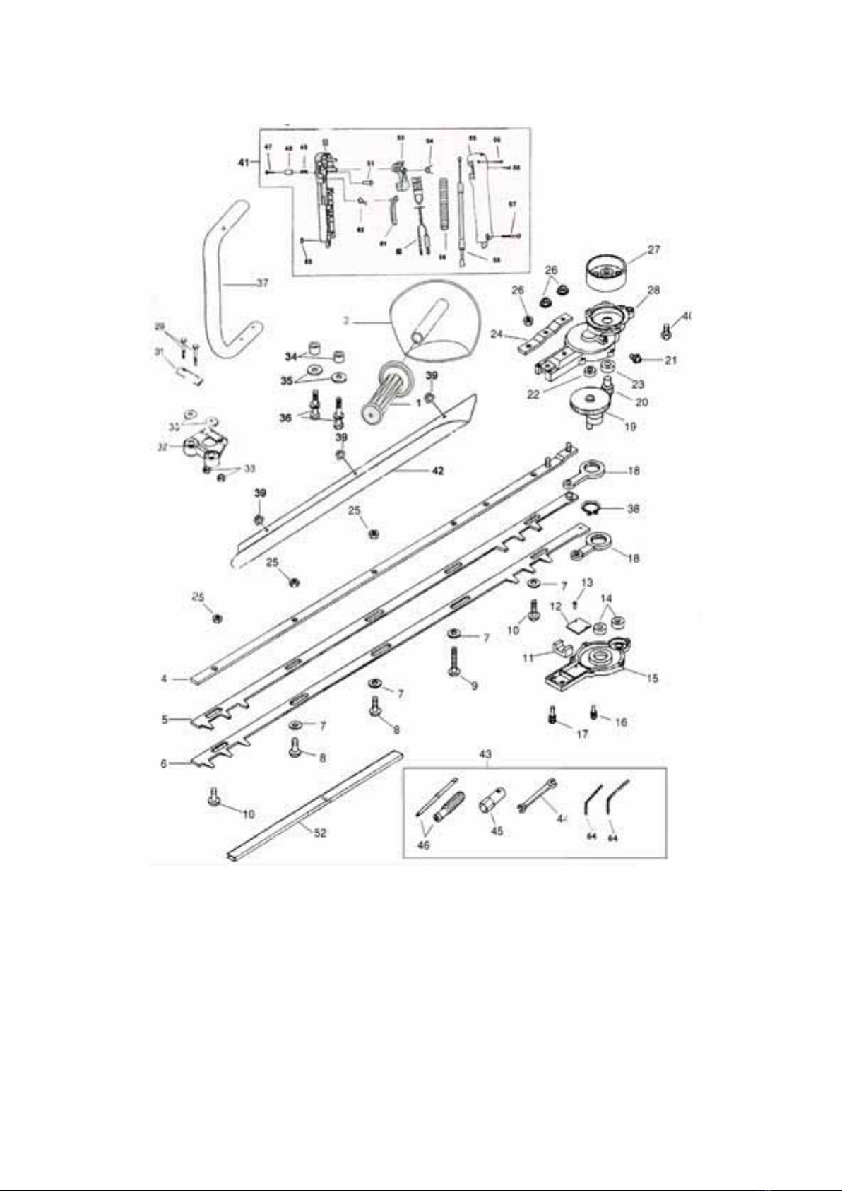
PARTS - CUTTER

Page 13
PARTS - CUTTER
No Part No Description Qty No Part No Description Qty
1 TH117-1 Grip 1 2 TH117-2 Handle 1
4 TH117-4 Guide Plate 1 5 TH117-5 Upper Blade 1
6 TH117-6 Lower Blade 1 7 TH117-7 Washer 1
8 TH117-8 Screw 1 9 TH117-9 Screw 1
10 TH117-10 Screw 4 11 TH117-11 Felt 2
12 TH117-12 Plate 1 13 TH117-13 Screw 2
14 TH117-14 Bearing 1 15 TH117-15 Lower Case 1
16 TH117-16 Bolt 2 17 TH117-17 Bolt 2
18 TH117-18 Con Rod 1 19 TH117-19 Gear 1
20 TH117-20 Pinion 2 21 TH117-21 Grease Nipple 2
22 TH117-22 Bearing 2 23 TH117-23 Bearing 1
24 TH117-24 Plate 1 25 TH117-25 Nut 1
26 TH117-26 Nut 1 27 TH117-27 Clutch Drum 1
28 TH117-28 Upper Case 1 29 TH117-29 Bolt 2
31 TH117-31 Plate 1 32 TH117-32 Bracket 2
33 TH117-33 Nut 1 35 TH117-35 Washer 1
36 TH117-36 Bolt 2 37 TH117-37 Rear Handle 2
38 TH117-38 Snap Ring 4 39 TH117-39 Nut 2
40 TH117-40 Bolt 1 41 TH117-41 Trigger Assy 1
42 TH117-42 Spoon 1 47 TH117-47 Screw 1
48 TH117-48 Button 1 49 TH117-49 Spring 1
50 TH117-50 Left Hand Trigger
Body 1 51 TH117-51 Lock 1
53 TH117-53 Throttle Trigger 1 54 TH117-54 Spring 1
55 TH117-55 Right Hand Trigger
Body 1 56 TH117-56 Screw 1
57 TH117-57 Screw 1 58 TH117-58 Throttle Cable 1
59 TH117-59 Cable Sleeve 1 60 TH117-60 Stop Switch 1
61 TH117-61 Safety Lever 1 62 TH117-62 Spring 1
63 TH117-63 Nut 1


To order spare parts and see the complete range of garden
machinery and garden equipment from Handy, visit:
www.thehandy.co.uk
Spares & Support: 01793 333212
Table of contents
Other The Handy Trimmer manuals

The Handy
The Handy THPLT-A Installation and maintenance instructions

The Handy
The Handy THMC-A User manual

The Handy
The Handy THEPHT500 User manual

The Handy
The Handy THLRT2600 Installation and maintenance instructions

The Handy
The Handy THBC26 Installation and maintenance instructions

The Handy
The Handy THPKLRT User manual

The Handy
The Handy THEPHT User manual

The Handy
The Handy THGSS User manual

The Handy
The Handy THHC22DB User manual

The Handy
The Handy THPLT Installation and maintenance instructions


