The Handy THBC26 Installation and maintenance instructions

Page 1
OPERATOR’S MANUAL AND PARTS LIST
PETROL BRUSHCUTTER - THBC26
Sales & Helpline 01793 333212
www.thehandy.co.uk
Before use please read & understand this manual, paying particular
attention to the safety instructions.
2011v1

Page 2
CONTENTS
SAFETY INSTRUCTIONS 3
MAJOR PARTS 4
FUEL 5
SPECIFICATIONS 5
ASSEMBLY 6-7
OPERATION 8
REPLACEMENT OF LINE 9
HINTS AND TIPS 10
MAINTENANCE 11
PARTS DIAGRAMS AND LISTS 12-15
EC DECLARATION OF CONFORMITY 16

Page 3
SAFETY INSTRUCTIONS
Read and understand the owner’s manual and the labels afxed to
the brushcutter. Learn its application and limitations as well as
the specic potential hazards. Retain these instructions for reference.
• Use sturdy footwear and a helmet with eye and ear protection.
Protect exposed parts of your body. Wear heavy duty gloves,
preferably made of leather.
• Do not operate the brushcutter if you are tired, ill or under the
influence of alcohol or drugs.
• Do not smoke when using the brushcutter and ensure caution when
handling fuel. We recommend that you fuel the machine at least 3m
away from where you wish to work in case any spilt fuel ignites when
starting the engine.
• Ensure that bystanders, children and pets keep well away when starting
or cutting - at least 15m.
• Inspect the brushcutter, and in particular the cutting blade, before use
for any worn or damaged parts. Do not use until the parts are repaired
or replaced.
• Before starting the engine make sure the blade is not in contact with
anything and have a clear work area and secure footing.
• Hold the brushcutter rmly with both hands when using and keep all
parts of your body away from the machine. Always ensure a safe rm
footing and do not over-reach or work above your waist.
• Always carry the brushcutter with the engine stopped.
• Never lay the hot brushcutter down on dry grass or any combustible
material where there is a re risk from the hot engine.
• Only use the brushcutter in good light and visibility. During cold weather
be aware of slippery or wet areas.
• Limit the amount of time over which the brushcutter is to used
continuously - about 30-40 minutes per session, taking 10-15 minutes
break. Try to keep the total amount of work performed in a day to under
2 hours.
• Please recycle the cardboard packaging in which the brushcutter is
delivered once you have checked that it is complete and working.
Always shut off the engine before setting it down.

Page 4
MAJOR PARTS
1 Fuel Tank
2 Starter
3 Air Cleaner
4 Fuel Tank Bracket
5 Housing
6 Throttle Cable
7 Lever Assembly
8 Safety Lever
9 Lever
10 Stop Switch
11 Handle Assembly
12 Bracket
13 Blade Guard
14 Gear Case
15 Blade
1 2 3 45 6
789
1 Warning! Attention
2 Read Owners Manual
3 Wear Head Protection
4 Keep Feet away from Cutter
5 Keep Bystanders away
6 Sound Power Level
7 Wear Strong Gloves
8 Wear Safety Boots
9 Keep Hands away from Cutter
Warning Labels on Machine

Page 5
FUEL
Petrol is very ammable. Avoid smoking or fuelling the
brushcutter anywhere near a ame or sparks. Allow the engine to cool
before re-fuelling. Fuel the engine at least 3m away from your work area.
• Use a ratio of 25:1 unleaded petrol to 2-stroke mineral oil.For synthetic or
semi-synthetic, use the oil manufacturer's ratio. Mix in the mixing bottle.
• Unscrew the fuel cap, and fuel the machine to 80% capacity. Fasten the
fuel cap tightly and wipe up any spillage.
• Ensure that any stored petrol/oil mixture (2-stroke) is clearly marked
in a separate can and only stored for 4-6 weeks. If the brushcutter is
not going to be used for a long period, drain the mixture from the fuel
tank, start the engine and drain the carburettor of any remaining fuel.
• Dispose of any unwanted 2-stroke mixture at an authorised recycling
point.
SPECIFICATIONS
Model THBC26
Blade 3T
Engine Air Cooled 2-stroke
Displacement 25.4cm³
Starter Recoil
Fuel Unleaded Petrol and 2 Stroke Oil
Fuel Tank Capacity 0.6 litres
Weight 6 kg

Page 6
ASSEMBLY
• Normally the brushcutter will arrive with the main shaft
(2) and fuel tank (1) attached.
• If not, attach using the four bolts (3) supplied.
Attach the Handle:
• Attach the D loop handle (1) over the rubber mount (3)
on the shaft and tighten the bolts (2).
Safety Guard:
• Attach the safety guard (6) as shown and x securely
using the four bolts M5x25 supplied.
Adjusting the Throttle Cable:
• After releasing the throttle lever, pull the throttle wire.
• The normal play is 1 or 2 mm when measured at the
carburettor side end.
• If the play is too short or long, take off the air cleaner
cover, loosen the locknut (1) and adjust (2).

Page 7
ASSEMBLY, cont’d
Attaching the Metal Blade:
• Lay the brushcutter on its back.
• Insert the allen key (7) into the gear shaft, line up the holes
in the blade holder and cover to stop the shaft turning.
• Place the blade onto the upper blade holder (5) and centre.
• Place the washer (3) onto the assembly, then the lower
blade holder (2) and finally the nut (1). Screw in an
anti-clockwise direction and tighten using the spanner.
• Release the allen key.
Note: to undo the nut to change the blade, turn clockwise.
Attaching the Line Trimmer Head:
• Lay the brushcutter on its back.
• Insert the allen key into the gear shaft as before to stop the
shaft turning.
• Remove washer (3 in pic above) but leave washer (5) on
the shaft.
• Screw the nylon head (3) anti-clockwise onto the
threaded shaft (2) and tighten manually.
• Release the allen key.
Note: to remove the trimmer head, turn clockwise.

Page 8
OPERATION
Before starting the engine, inspect the entire unit for loose
ttings or fuel leaks, and ensure that the cutting attachment
is securely fastened.
• Place the machine on a at surface away from the area
in which you intend to work.
• Fuel the machine to 80% capacity.
• Put the ignition switch (1) to “I” (start position).
• Move the choke lever (2-3) to the closed position
• Press the primer button 10 times.
• Whilst holding the unit rmly, pull on the starter rope
until the machine res.
• Open the choke up gradually and pull the starter rope
again until the machine starts.
• Allow the engine to run for 2 to 3 minutes to warm up.
If starting a warm engine there may be no need to prime
the engine or put the choke lever to “closed”.
Stopping the Engine:
• Return the throttle to the idling position.
• Push the ignition switch to “O” (stop position).
Attaching the Harness:
• Attach the clip on the harness to the loop on the control
handle and adjust to suit the operator.
Closed
Open

Page 9
REPLACEMENT OF LINE
Follow these steps to replace the cutting line.
• Stop the engine.
• Lay the trimmer on the oor so that the cutting head is facing up.
• Squeeze the head on both sidesat right angles to the eyelets.
• Remove the empty spool being careful not to lose the spring
behind the head.
• Clean the head thoroughly and inspect for any worn or damaged
parts.
To reload the spool with line:
• Cut two lengths of spare line 3 metres long.
• Position each line in the two holes located in the centre of the
spool and wind in the direction of the arrow on the spool.
• Wind the line on until you have about 15cm left.
• Secure the lines into the slots on the spool.
• Replace the spring and reposition the spool with the two cords in
the eyelets.
• Close the spool making sure it snaps together.
• Release the lines from the spool by sharply pulling each line
while pushing down on the spool.

Page 10
HINTS AND TIPS
Using the Metal Blade:
Use the metal blade attachment for cutting thicker grass, weeds and undergrowth.
Adjust the cutting speed to suit the material to be cut. Grass at medium speed and thick
weeds and shrubs at high speed.
If you operate at low speed there is a greater chance of weeds and twigs getting caught
around the blade.
Use the brushcutter like a scythe - sweep it to the right and left just above ground level
when cutting grass and light brush.
Using the Line Trimmer Head:
Use the nylon head for cutting grass around fence posts and trees where a metal blade
could become damaged.
When the two nylon cords become too short, accelerate the engine and bump the nylon
head on the ground. The two cords will automatically feed out and be cut off at the correct
length by the blade on the guard.

Page 11
MAINTENANCE
To ensure a long service life and to avoid any damage to the brushcutter, perform the
following maintenance at regular intervals.
Air Filter:
Check and clean the Air Filter regularly to ensure optimum performance.
Remove the air lter cover, take out the element and wash in lukewarm water. Allow to
dry completely and then replace. Clean off any excessive dirt and dust.
Fuel Filter:
Take the lter out of the fuelling port using a small wire hook. Disconnect the lter
assembly from the fuel pipe and unhook the retainer to disassemble it. Clean the
components with petrol.
Spark Plug:
Check the spark plug periodically and ensure that the gap between the electrodes is
between 0.6 and 0.7mm. Adjust where necessary using the universal wrench supplied.
If the spark plug is clogged with carbon, clean thoroughly or replace.
Grease:
Apply multipurpose grease to the gear head after every 25 hours of use.
Idle Adjustment Screw:
If the blade continues to run on when you release the throttle lever or the engine stops,
it may be necessary to adjust the Idle Adjustment Screw.
Turning it clockwise increases the engine speed and turning it anti-clockwise decreases
the speed.
Storage:
When storing the brushcutter for any length of time it is important to drain down the fuel,
both in the tank and the carburettor. Either drain the fuel manually or run the engine
until it uses up all the fuel.
Remove the spark plug and add a few drops of oil into the spark plug hole.
Pull the starter cord gently to conrm that a lm of oil covers the engine inside.
Tighten the spark plug. Clean dirt or dust from the cutter blade and the outside of the
machine and wipe with an oily cloth. Store in a dry place.
Page 12
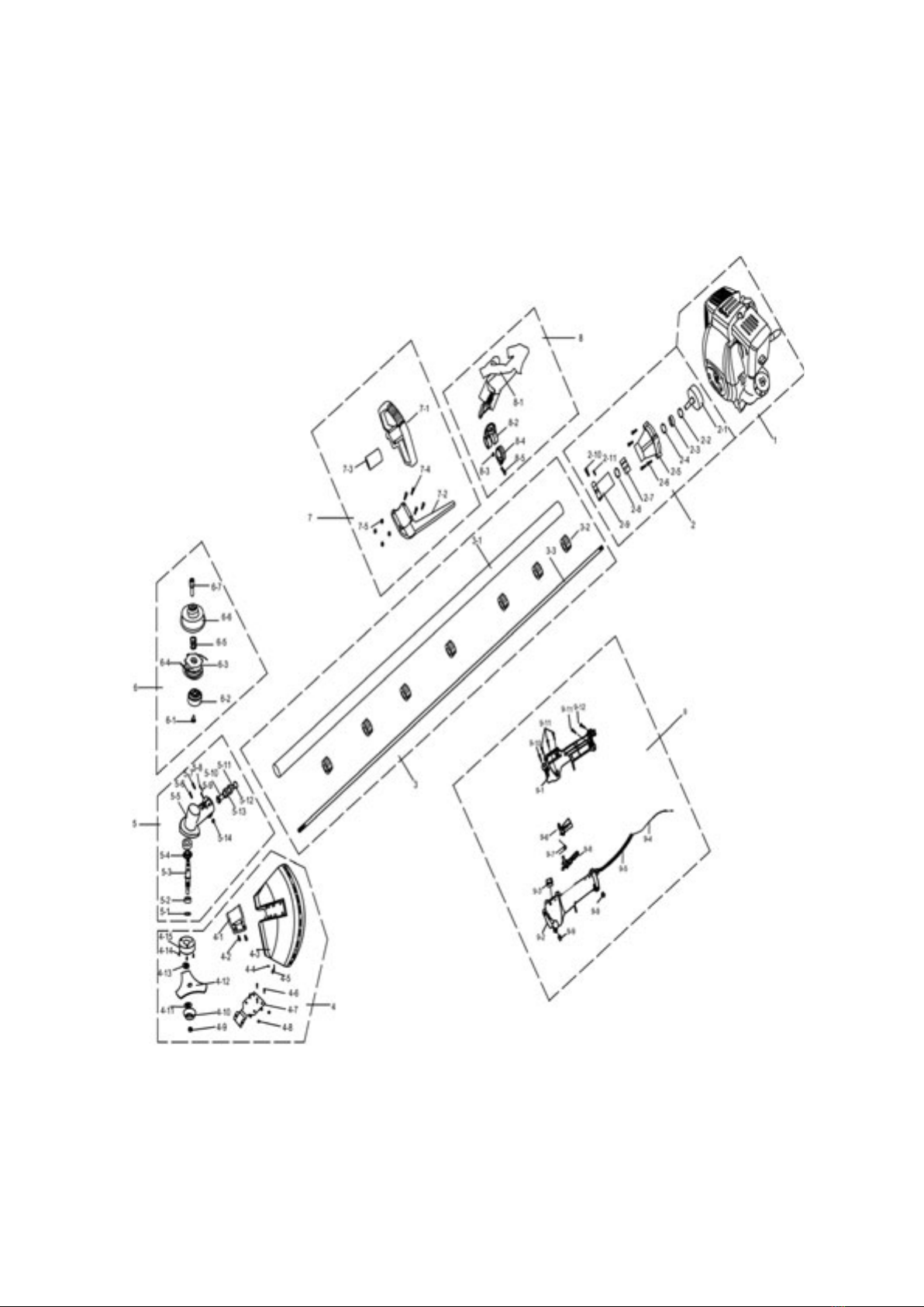
PARTS DIAGRAM- DRIVE UNIT

Page 13
PARTS LIST - DRIVE UNIT
No Part No Description Qty
1 TH125-1 Engine (see separate list) 1
2 TH125-2 Clutch Assembly 1
3 TH125-3 Drive Shaft Complete 1
3-1 TH125-3-1 Drive Shaft Cover 1
3-2 TH125-3-2 Bush 8
3-3 TH125-3-3 Shaft 1
4-1 TH125-4-1 Bracket 1
4-2 TH125-4-2 Bolt M5x25 2
4-3 TH125-4-3 Guard 1
4-4 TH125-4-4 Screw 1
4-5 TH125-4-5 Blade 1
4-6 TH125-4-6 Bolt M5x25 4
4-7 TH125-4-7 Plate 1
4-8 TH125-4-8 Nut M5 4
4-9 TH125-4-9 Nut M10 1
4-10 TH125-4-10 Cover 1
4-11 TH125-4-11 Holder B 1
4-12 TH125-4-12 Blade 1
4-13 TH125-4-13 Holder A 1
4-14 TH125-4-14 Cover 1
5 TH125-5 Gearcase Assembly 1
6 TH125-6 Line Head Assembly 1
7 TH125-7 Handle Assembly 1
9 TH125-9 Throttle Handle Assembly 1
Page 14
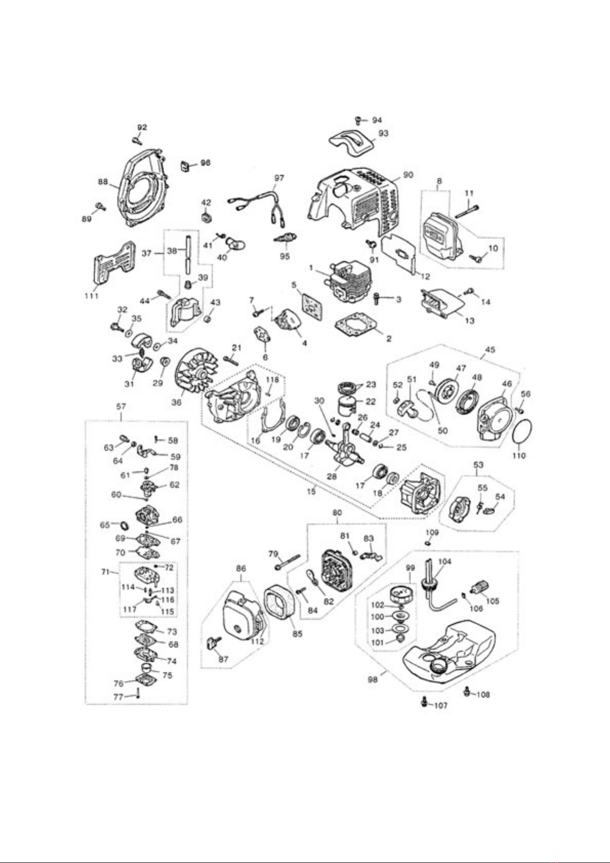
PARTS DIAGRAM- ENGINE

Page 15
PARTS LIST - ENGINE
No Part No Description Qty No Part No Description Qty
1 TH126-1 Cylinder 1 40 TH126-40 Cap, plug 1
2 TH126-2 Gasket, Base 1 41 TH126-41 Spring 1
3 TH126-3 Bolt 2 42 TH126-42 Grommet 1
4 TH126-4 Insulator 1 43 TH126-43 Spacer 2
5 TH126-5 Gasket, Insulator 1 44 TH126-44 Bolt 2
6 TH126-6 Gasket, Carburettor 1 45 TH126-45 Recoil Assy 1
7 TH126-7 Screw 2 53 TH126-53 Pulley Assy 1
8 TH126-8 Mufer Assy 1 56 TH126-56 Screw 4
10 TH126-10 Arrestor 1 57 TH126-57 Carburettor Assy 1
11 TH126-11 Bolt 2 79 TH126-79 Screw 2
12 TH126-12 Gasket, Mufer 1 80 TH126-80 Body Assembly 1
13 TH126-13 Plate, Mufer 1 81 TH126-81 Sleeve 2
14 TH126-14 Screw 1 82 TH126-82 Plate, Choke 1
15 TH126-15 Crankcase, comp 1 83 TH126-83 Lever, Choke 1
16 TH126-16 Gasket, Case 1 84 TH126-84 Screw 1
17 TH126-17 Bearing 2 85 TH126-85 Element 1
18 TH126-18 Oil Seal 1 86 TH126-86 Cover Assembly 1
19 TH126-19 Oil Seal 1 88 TH126-88 Cover, Fan 1
20 TH126-20 Snap Ring 1 89 TH126-89 Screw 4
21 TH126-21 Screw 4 90 TH126-90 Cover, Engine 1
22 TH126-22 Piston 1 91 TH126-91 Screw 1
23 TH126-23 Ring 2 92 TH126-92 Screw 2
24 TH126-24 Pin 1 93 TH126-93 Guard, Plug 1
25 TH126-25 Snap Ring 2 94 TH126-94 Screw 1
26 TH126-26 Bearing 1 95 TH126-95 Spark Plug 1
27 TH126-27 Washer 2 96 TH126-96 Grommet 1
28 TH126-28 Crankshaft comp 1 97 TH126-97 Cord complete 1
29 TH126-29 Nut 1 98 TH126-98 Tank Assy 1
30 TH126-30 Key 1 99 TH126-99 Cap Assy 1
31 TH126-31 Shoe, Clutch 2 104 TH126-104 Pipe comp 1
32 TH126-32 Screw 2 105 TH126-105 Filter Assy 1
33 TH126-33 Spring 1 106 TH126-106 Clip 1
34 TH126-34 Washer 2 107 TH126-107 Screw 2
35 TH126-35 Washer 2 108 TH126-108 Screw 1
36 TH126-36 Rotor 1 109 TH126-109 Clip 1
37 TH126-37 Coil Assy 1 110 TH126-110 Label 1
118 TH126-118 Pin 3


To order spare parts and see the complete range of garden
machinery and garden equipment from Handy, visit:
www.thehandy.co.uk
Spares & Support: 01793 333212
Table of contents
Other The Handy Trimmer manuals

The Handy
The Handy THPKLRT User manual

The Handy
The Handy THGSS User manual

The Handy
The Handy THMC-A User manual

The Handy
The Handy THEPHT User manual

The Handy
The Handy THPLT Installation and maintenance instructions

The Handy
The Handy THHC22DB User manual

The Handy
The Handy THHC30SB Installation and maintenance instructions

The Handy
The Handy THEPHT500 User manual

The Handy
The Handy THPLT-A Installation and maintenance instructions

The Handy
The Handy THLRT2600 Installation and maintenance instructions


