The Original ScrapBox Ultimate Sewing Box User manual
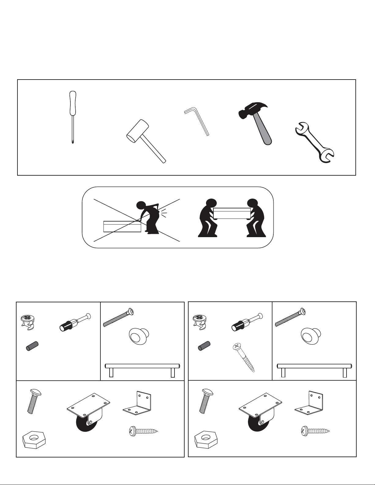
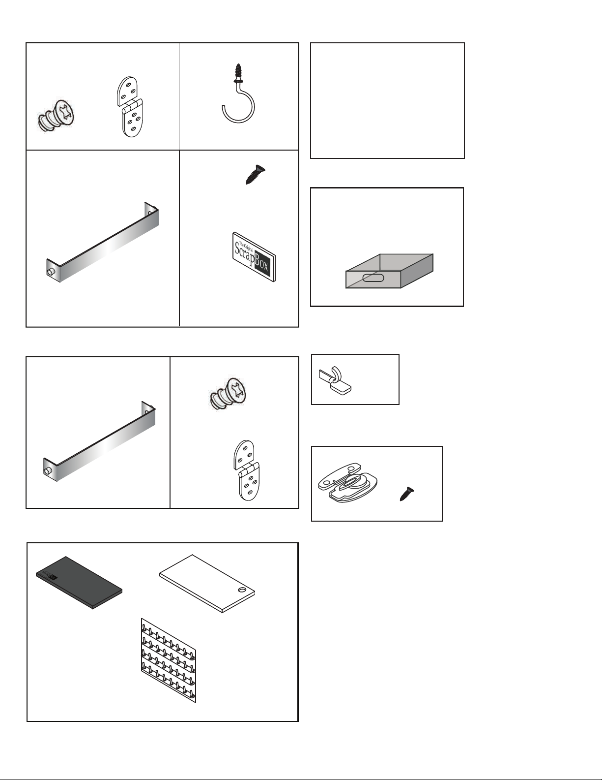
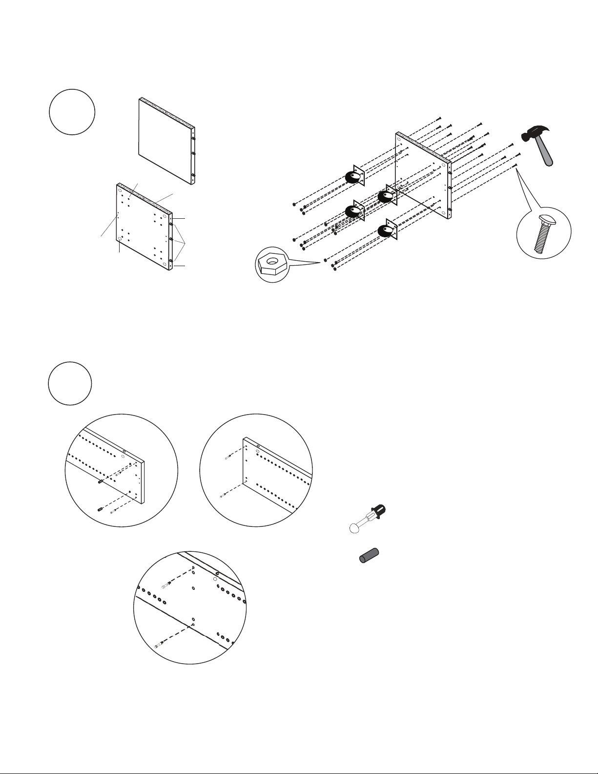
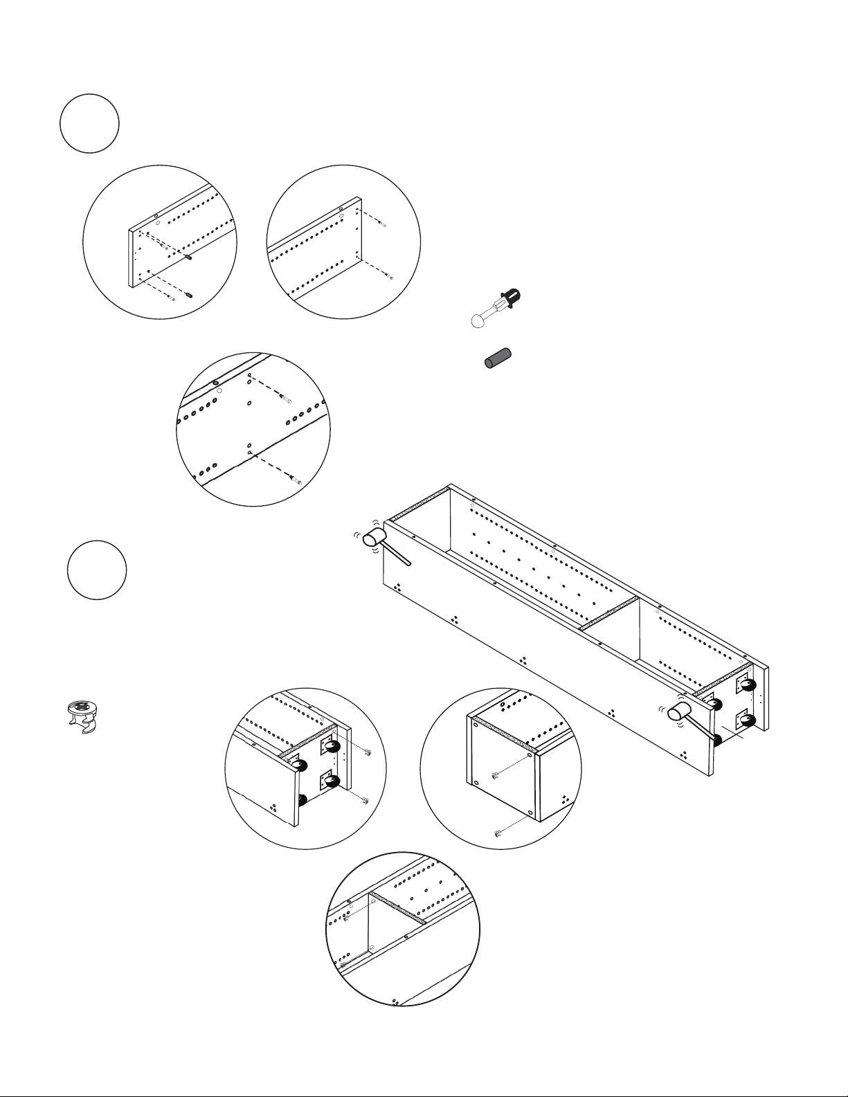
https://www.theoriginalscrapbox.com/pages/sewsteady-link
We’ve been working hard to bring you a more customer friendly build in 2018
and we need your feedback. After assembling your Ultimate Sewing Box, please
For this build, there is no companion video tutorial.
We have also partnered with Sew Steady to improve the functionality of our product.
For your free Center Desk Acrylic Table Insert, please complete the online form
found here (case sensitive):
If you have questions regarding your Ultimate Sewing Box, please contact us.
USA/CAN (801) 226-2686, M-F 9am-5pm MST (Utah)
customerservice@theoriginalscrapbox.com
www.theoriginalscrapbox.com
You have received The Ultimate Sewing Box!
Thank you for your continued interest in our products.
We hope The Ultimate Sewing Box will provide a place to organize and create.
- The Original ScrapBox Team
AUS #: 61-4-1-4441-8022
GER #: 49-40-57-00-39-98
Cnrtlos

2Proprietary, patented product and assembly instructions. Do not copy or distribute.
All panels must be kept at a 90 (Right Angle)
All bases, lids, and shelves must be installed and kept at a right angle (90 ) with side panels.
Once all pieces are fully connected the design is very strong and will last many years!
IMPORTANT
PLEASE READ BEFORE ASSEMBLY
All panels must be installed at a right angle.
Damage may occur if not properly assembled.
o
90
o
90
o
90
o
90
o

3
Proprietary, patented product and assembly instructions. Do not copy or distribute.
TOOLS NEEDED:
Our furniture is designed to be built with two people.
Please do not try to build alone.
x16
x16
x4 x4
LEFT BOX HARDWARE: RIGHT BOX HARDWARE:
Door Knob
Bolts
x16
Bolts
Nuts
x16
Nuts
Wheels
Small Base
support pins
x4
MADE IN THE USA
Last Updated: 07/25/2018
The Ultimate Sewing Box: Assembly Instructions
Phillips Screw Driver Hammer
10mm wrench
(or socket wrench
with extension)
Rubber Mallet
(included)
Locking
Cams
x20 x20
Posts
14mm
Washer Screws
x8
1” Screw
(or x2 for Ergo White)
(or x1 door handle
for Ergo White)
x1 x1
x1
Angle Brackets
x2
Door Knob
Wheels
Small Base
support pins
x4
Locking
Cams
x24 x24
Posts
1 1/2”
Screws
x4
14mm
Washer Screws
x8
1” Screw
(or x2 for Ergo White)
(or x1 door handle
for Ergo White)
x1
Angle Brackets
x2
Allen Wrench
(included)

4Proprietary, patented product and assembly instructions. Do not copy or distribute.
4
x
Barrel Locks
for fold-out table
3/4” Screws
16
x
2
x
Fold down
Work Table
x1
Back fold out
table
x2
Rubber Cap
x1
Left Pivot
Bracket
x1
Right Pivot
Bracket
x4
1/2” washer screws
CENTER BOX HARDWARE:
CENTER SLIDING TABLE HARDWARE WORK TABLES HARDWARE:
Small Base
Support Pins
x4
Long Table Legs
Metal
Shelf Holders
For Hinges
13mm Euro Screws
Hinges
13mm Euro Screws
3/4” table
leg screws
x16
Posts
x8
Locking
Cams
x16 14mm
Washer Screws
x8
Angle Brackets
x2
x4
Wheels
x16
Nuts
x16
Bolts
1 1/2”
Screws
for divider panels
x16
x78
x13
For Back Panel
25mm Euro Screws
x23
x24
x8
x2
Short Table Legs
3/4” table
leg screws
x8
x2
3
x
Hinges
Recessed on
side opposite
of barrel
x3
Hinges
Recessed on
side opposite
of barrel
x26
13mm Euro Screws
x2
Rails
x8
3/4” washer screws
x1
Center Box
Sliding Table

5
Proprietary, patented product and assembly instructions. Do not copy or distribute.
72
x
Plastic Shelf Pegs
Vertical Adjustable
Shelf Hardware:
3
x
Offset Hinges
21
x
13mm Euro Screws
2
x
4
x
Acrylic Guards
LEFT SWING BOX HARDWARE:
RIGHT SWING BOX HARDWARE:
ACCESSORIES INCLUDED:
21
x
13mm Euro Screws
1
x
Name Plate
(May already be installed)
6
x
Metal Hooks
12- 13 x 13 (8 in center box, 4 in right box
2- 13 x 7 1/2 (Center box)
4 - 3 x 13 Shelves (Right box)
Left box:
5 - Thick Shelves (13” x 16.5”) - upper
2- Thick Shelves (15.75” x 16.5”) - lower
Right box:
2- Thick Shelves (13” x 16.5”) - upper
2- Thick Shelves (15.75” x 16.5”) - lower
Center box:
1- Long Thick Shelf
SHELVES INCLUDED
CLEAR TOTES INCLUDED:
9 - Shoebox w/ 2 dividers each
17 - Notions w/ 3 dividers each
15 - Large Totes (12 1/4 x 12 1/4 x 3)
5 - Notion Tray Inserts
1
x
Acrylic Guards
3
x
Offset Hinges
1
x
Sewing machine foam mat
1
x
Table insert cover
Spool Holder
2
x
Clear Plastic Totes
Optional
Sash Lock
x4
Sash Lock
x1
14mm
Self-tapping
screws
Please visit the link on page 1
to submit your request for a
free Sew Steady Clear Plastic
Table Insert.

6Proprietary, patented product and assembly instructions. Do not copy or distribute.
Left Box
Left Box
Lid
Base
16 Bolts
16 Nuts
Bottom View
LEFT BOX Build on a blanket for best results
1
Left Box: Side 1
Small base support pins
2
Install (2) small base support pins and
posts into bottom of Side 1 as shown.
Insert (6) posts into post holes in top,
bottom and center of Side 1 as shown.
Green dowels
Post hole
Locking
Cam hole
Unfinished edge
Pre-drilled
wheel screw
holes
Pre-drilled
angle bracket
holes
Post hole
Hammer (16) bolts into top of base.
Install (4) wheels onto bolts.
Tighten with (16) nuts using a
wrench or socket wrench.
Do NOT overtighten screws (wheels should spin freely)
x2
x6 Posts
TOP
BOTTOM
CENTER

7
Proprietary, patented product and assembly instructions. Do not copy or distribute.
LEFT BOX
3
With finished edges of Base & Lid facing down,
match up posts on Side 1 with post holes.
Use mallet to tap Base and Lid into Side 1.
Repeat for the Left Box Shelf.
**Be sure the Recessed Hinge Pockets are
closest to the ground and facing the Lid.
IMPORTANT
All panels must be installed at a right angle.
Damage may occur if not properly assembled.
Left Box
Shelf
Recessed hinge pockets
TOP VIEW
Left Box
Side 1
Left Box
Shelf
Left Box
Lid
Left Box
Base
4
BASE LID
Locking
Cams
x6
CENTER
Insert Cams into underside of Base &
Center Shelf and top side of Lid
(outside of the box).
Use Allen Wrench to turn Cams until
locked in place.

8Proprietary, patented product and assembly instructions. Do not copy or distribute.
LEFT BOX
Left Box
Side 1
Left Box
Base
Left Box
Side 2
Left Box: Side 2
Small base support pins
5
Install (2) small base support pins and
posts into bottom of Side 2 as shown.
Insert (6) posts into post holes in top,
bottom and center of Side 2 as shown.
x2
x6 Posts
TOP
BOTTOM
CENTER
CENTER
BASE LID
Left Box
Side 1
6
Use mallet to carefully tap Side 2
into the post holes on Base, Lid and Shelf.
Insert 6 more cams & tighten until locked.
Locking
Cams
x6
*Note that again, cams will insert
into top side of Lid (outside of
the box) and the undersides of
Shelf and Base.

9
Proprietary, patented product and assembly instructions. Do not copy or distribute.
Left Box
Side 1
Left Box
Base
Left Box
Side 2
Left Box
Base
Left Box
Side 2
LEFT BOX
8
CAREFULLY Set door over 8 posts.
*Make sure door knob hole is
over Side 1.
DO NOT FORCE onto posts.
7
Insert 9 Posts HEAD DOWN
into Post Holes on the edge
of Sides 1 & 2.
x9 Posts
Head
Be certain each post is secure.
Next, carefully turn box over so that DOOR is facing down.
Be sure that door does not slide off posts.

10 Proprietary, patented product and assembly instructions. Do not copy or distribute.
Left Box
Side 1
Left Swing Door
with Shelves
13mm
Left Box
Side 1
Attaches to Left Swing door
Attaches to Left Box Side 1
9
LEFT BOX
Locking
Cams
x8
13mm Euro Screws
x21
10
Install (3) offset hinges to Left Box
Side 1 using (12) 13mm Euro Screws.
Do not tighten until attaching swing door.
Attach Left Swing Door with Shelves
to Left Box using (9) 13 mm Euro Screws.
Tighten all screws.
CAUTION: Leave the Left Box laying on its side for a future step
and until attaching the Center Box.
Insert 8 Cams along both sides of the interior
of the box and turn with Allen Wrench until
locked in place.

11
Proprietary, patented product and assembly instructions. Do not copy or distribute.
Right Box
Right Box
Lid
Base
16 Bolts
16 Nuts
Bottom View
RIGHTBOX
Build on a blanket for best results
1
Right Box: Side 1 (Repeat for Side 2)
Small base support pins
2
Install (2) small base support pins and
posts into bottom of Side 1 as shown.
Insert (8) posts into post holes in top,
bottom and center of Side 1 as shown.
* Repeat with (8) more posts and (2) more
base support pins on Side 2.
Green dowels
Post hole
Locking
Cam hole
Unfinished edge
Pre-drilled
wheel screw
holes
Pre-drilled
angle bracket
holes
Post hole
Hammer (16) bolts into top of base.
Install (4) wheels onto bolts.
Tighten with (16) nuts using a
wrench or socket wrench.
Do NOT over tighten screws
(wheels should spin freely)
x2
x8 Posts
TOP
BOTTOM
FOR SHELF 1 FOR SHELF 2

12 Proprietary, patented product and assembly instructions. Do not copy or distribute.
RIGHT BOX
3
With finished edges of Base & Lid facing down,
match up posts on Side 1 with post holes.
Use mallet to tap Base and Lid into Side 1.
Repeat for the Right Box Shelf 1 & 2.
**Be sure the Recessed Hinge Pockets
on Shelf 1 are closest to the ground and facing
the Lid.
Right Box
Shelf 1
Recessed hinge pockets
TOP VIEW
Right Box
Side 1 Right Box
Shelf 1
Right Box
Shelf 2
Right Box
Lid
Right Box
Base
4
BASE
FOR SHELF 1
Locking
Cams
x8
LID
FOR SHELF 2
Insert Cams into undersides
of Base and Shelves 1 & 2
and top side of Lid (outside
of the box). Turn Cams with
Allen Wrench until locked in
place.

13
Proprietary, patented product and assembly instructions. Do not copy or distribute.
RIGHT BOX
Locking
Cams
x8
Right Box
Side 2
Right Box
Side 2
6
Insert 9 Posts HEAD DOWN
into Post Holes on the edge
of Sides 1 & 2.
x9 Posts
Head
5
Use mallet to carefully tap Side 2 into the post
holes on Base, Lid and Shelves. Insert and lock
(8) more Cams.
*Note that 2 cams will
insert into top side of Lid
(outside of the box) and
the other four will insert
into the undersides of
Shelves and Base.

14 Proprietary, patented product and assembly instructions. Do not copy or distribute.
RIGHT BOX
Right Box
Side 2
7
CAREFULLY Set door over 8 posts.
DO NOT FORCE onto posts.
*Make sure door knob hole is
over Side 1.
Be certain each post is secure.
Next, carefully turn box over so that DOOR is facing down.
Be sure that door does not slide off posts.
Right Box
Side 1
8Locking
Cams
x8
Insert 8 Cams along both sides of the interior of
the box and turn with Allen Wrench until locked
in place.
*Note that all 8 cams will
insert into interior of the
box.

15
Proprietary, patented product and assembly instructions. Do not copy or distribute.
Next, you will use shelves as spacers to properly align and install
the Right Box Divider. Take a moment to locate these shelves:
3 x 13”
Notions
Shelf
x6
13 x 13”
shelves
x2
10
Insert Shelf Pegs in
holes on Side 1 of Right Box Divider
to match peg placement from
step 9
Shelf Pegs
x8
Right Box
Side 1
Divider
1
4
7
10
RIGHT BOX
Right Box
Side 1
9
Insert Shelf Pegs in
holes on Side 2.
We recommend placing
pegs as shown.
1
4
7
10
147
10
Shelf Pegs
x8

16 Proprietary, patented product and assembly instructions. Do not copy or distribute.
RIGHT BOX
Right Box
Side 1
11
Slide divider in and align with
pilot holes on lid and top shelf.
Add shelves as shown
Right Box
Side 1
12
Once divider and shelves are in place
make sure they fit tightly.
Use a Phillips screw driver to
MANUALLY insert (4) 1 1/4” screws
into pilot holes to secure divider.
**Divider MUST be screwed in MANUALLY in order to avoid damaging your WorkBox.**
1 1/2”
Screws
x4

17
Proprietary, patented product and assembly instructions. Do not copy or distribute.
RIGHT BOX
CAUTION: Leave the Left Box laying on its side for a future step
and until attaching the Center Box.
Remove shelf spacers and set aside. Carefully turn box onto Side 2.
Right Swing Door
with Felt Velcro Panel
Right Box
Side 1
13mm
Attaches to Right Swing door
Attaches to Right Box Side 1
13mm Euro Screws
x21
13
Install (3) offset hinges to Right Box
Side 1 using (12) 13mm Euro Screws.
Do not tighten until attaching swing door.
Attach Right Swing Door with Felt Velcro Panel
to Right Box using (9) 13 mm Euro Screws.
Tighten all screws.

18 Proprietary, patented product and assembly instructions. Do not copy or distribute.
Center Box
Shelf 2
Top Side
CENTER BOX
Build on a blanket for best results
Use Phillips Screw Driver to MANUALLY
insert (4) 1 1/2” screws into pre-drilled
screw holes on top side of Center Box Lid
to secure Dividers.
**Dividers must be screwed in MANUALLY
to avoid damaging your Ultimate SewingBox.
3
Center Box
Lid
Bottom Side
1 1/2”
Screws
for divider panels
x4
Align & insert green dowels
into corresponding dowel holes
on top side of Shelf 2.
Use Rubber Mallet to carefully tap
Shelf 2 until secure.
2
1
Align green dowels on Dividers with
dowel holes on lid.
Use Rubber Mallet to carefully tap
Dividers into place until secure.
Center Box
Divider
Center Box
Divider
Finished Edge
Center Box
Divider
Center Box
Divider
Center Box
Lid
Top Side
Center Box
Lid
Top Side

19
Proprietary, patented product and assembly instructions. Do not copy or distribute.
Center Box
Lid
Bottom
Side
CENTER BOX
4
Use Phillips Screw Driver to MANUALLY
insert (4) 1 1/2” screws into pre-drilled
screw holes on bottom side of Shelf 2
to secure Dividers.
1 1/2”
Screws
for divider panels
x4
Center Box
Divider
**Shelf must be screwed into dividers
MANUALLY to avoid damaging your Ultimate SewingBox.
Center Box
Divider
Center Box
Shelf 2
Bottom Side
Center Box
Divider
Next, you will use several small notions shelves as spacers
to lift top section in order to attach sides. Take a moment to locate these shelves:
13 x 13” Shelves
x12
Arrange the assembled section
as shown.
5
With TWO PEOPLE, Carefully lift
each corner and arrange stacks of
(3) 3 x 13” Notions Shelves under
each of the corners indicated.
Finished Edge

20 Proprietary, patented product and assembly instructions. Do not copy or distribute.
CENTER BOX
Side 1
Insert (16) Posts into
corresponding post
holes on Sides 1 & 2.
Also add (4) Base Support
pins to corresponding
Holes in Side 1 & 2.
x16
Posts
x4
Base Support
Pins
6
Center Box
Divider
Stand Side 1 on its edge and
be sure posts, dowels & pins
are aligned. Use Mallet to tap
Side 1 carefully into built section.
7
Finished Edge
Side 2
Table of contents
Popular Indoor Furnishing manuals by other brands

eliving FURNITURE
eliving FURNITURE Jun Series Assembly instructions

ofichairs
ofichairs Zenit pro manual

Stellar Home
Stellar Home S 220 Assembly instructions

OYPLA Home
OYPLA Home 4448 user manual

New Classic Furniture
New Classic Furniture TRELLIS D5030-50S Assembly instructions

Opti-Med
Opti-Med JM-C02 user manual