theben HTC SendoClic 907 0 690 User manual

1103054501 © 10.2010 Theben HTS
Art. Nr. 907 0 690
User remote control
SendoClic
DK
D
F
GB
E
I
NL
S
N
FIN
Bedienungsanleitung 2
Notice d'utilisation 22
Operating instructions 42
Manual de instrucciones 62
Istruzioni per l'uso 82
Gebruikershandleiding 102
Bruksanvisning 122
Bruksanvisning 142
Käyttöohje 162
Betjeningsvejledning 182

42
English Operating instructions
User remote control
SendoClic
Table of contents
1. Use .....................................................43
2. Function and performance characteristics . . . . . . . . . . . . . . . . . . . . . . . . . 43
3. Operation.................................................44
4. Lightinggroups ............................................48
5. Programming..............................................50
6. Technicaldata .............................................57
7. Guarantee ................................................58
8. Troubleshooting............................................59

43
GB
Thank you for purchasing a Theben HTS device and putting your trust in us.
1. Use
The remote control is exclusively intended for the use as contractually agreed be-
tween the manufacturer and the user.Any other use is considered to be unaccept-
able. The manufacturer does not accept liability for any resulting damages.
Please also read the presence detector operating instructions and familiarise your-
self with its functions. In particular, this provides information on the remote control
option and dimming function of the presence detector as well as other device-
specic responses.
2. Function and performance characteristics
The SendoClic infrared remote control makes it easy to switch and dim lighting
usingTheben HTS presence detectors (see page 57).SendoClic has two channels for
controlling two lighting groups.
SendoClic provides the option of storing two different lighting scenes which can
be retrieved anytime at the touch of a key.

44
3. Operation
For channels 1 and 2 together:
ON Switches lighting on
OFF Switches lighting off
Scene 1 Calls up Scene 1, programming
Scene 2 Calls up Scene 2, programming
For channels 1 and 2 separately:
switching on, increasing light level
switching off, decreasing light level
ON
OFF
SCENE
2
1
Channel 2
Channel 1
LED

45
GB
●The detector conrms a valid command with a icker of the
red LED for a half seconds.
●An invalid command or an incompatible IR-group-address
are indicated by the LED briey lighting up once.
●If the presence detector does not react
-this means that the remote control has not been adjusted
to the detector accurately enough
-or that the detector cannot be remotely operated using
this remote control.
-or that the battery is almost at
3.1 Switching the lighting
Briey press the
/
key switches the relevant channel on/off (lighting group).
Pressing the ON/OFF buttons switches both channels on/off simultaneously.
3.2 Dimming the lighting
Pressing and holding down the
/
keys dims the relevant channel (light-
ing group) brighter/darker. Press the
/
keys until the desired brightness is
achieved.
This interrupts automatic lighting control.
Note: Dimming is only possible with presence detectors that have a dimming
function.

46
3.3 Lighting scenes
A „lighting scene“ is the term used to describe a lighting situation in a room.When
a scene is called up, both lighting groups change intensity to the predened values
or switche to the preset condition. SendoClic enables two frequently used lighting
scenes to be stored and reproduced at any time by pressing a key.
Retrieving a scene
●Briey pressing scene keys 1 or 2 calls up the stored scene.
Presence detectors with dimming and switching functionality
●All lighting groups dim to the stored values.
●When a stored scene is called up the automatic light control is suspended.
Presence detectors with switching functionality only
●The lighting groups adopt the stored condition (On or Off).
Saving a scene
3. Setting an individual lighting situation requires each lighting group to be
dimmed to the desired value or switched on or off.
4. Press/hold scene keys 1 or 2 for more than 5 seconds stores the current bright-
ness or the condition (On or Off) of both lighting groups as a scene

47
GB
Ending a scene
Automatic switching off of lighting using the presence detector when the room
is unoccupied or manual switching off using SendoClic ends the lighting scene.
Automatic operation is reactivated.
Presence detectors with dimming and switching functionality
●Automatic switching off of lighting when the room is unoccupied or manual
switching off ends the lighting scene control. Automatic operation is reacti-
vated.
●Lighting scene control is ended using the ON key without switching off the
lighting. Automatic operation is reactivated.
Presence detectors with switching functionality only
●Automatic switching off of lighting when the room is unoccupied terminates
the lighting scene control. Automatic operation is reactivated.

48
The following operations should only be carried out by a qualied
electrician or the technical support service:
4. Lighting groups
There are often several lighting groups in one room. Up to two lighting groups can
be allocated to SendoClic's two channels. This allows two neighbouring lighting
groups to be separated and controlled individually.
The presence detector channels (lighting groups) and the SendoClic channels are
linked via a IR-group-address. Three IR-group-addresses are available for linking.
4.1 IR-group-addresses in general
The operation of a lighting group requires that the IR-group-address of the pres-
ence detector channel and the SendoClic channel correspond.
The SendoClic can be used to program the IR-group-address of the presence detec-
tor channels. Programming is followed by the allocation of the IR-group-addresses
to the SendoClic channels.

49
GB
ON
OFF
SCENE
2
1
AA
I
I
I I
I I
PlanoCentro 101-A-230V PlanoCentro 101-A-230V
ON
OFF
SCENE
2
1
AA B
I I
I
I I
I I
PlanoCentro A-KNX PlanoCentro A-KNX
IR-group-address
IR-group-address
Channel
Channel 2
Channel 1

50
Factory setting
The SendoClic channels are set to the IR-group-address I+ I I (coding switch
position 2) on delivery.
The factory setting of the presence detector can be found in the relevant operating
instructions.
When is adjustment required?
In some cases this setting has to be changed:
●Combination of lighting groups with several presence detectors.
●Unwanted inuence of neighbouring lighting groups by using the SendoClic
5. Programming
5.1 General
Programming is the allocation of a IR-group-address to the presence detector chan-
nels.
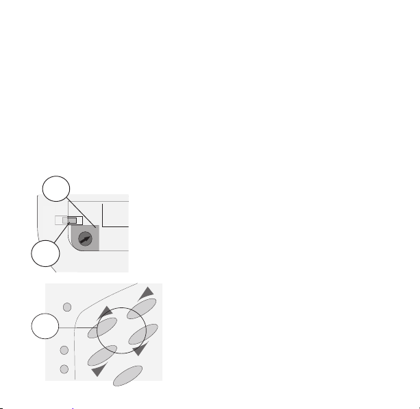
1. Programming is performed using the coding switch for group selection as well
as the program buttons.They are located in the battery compartment.
See chapter 5.2 page 51
2. After programming the presence detector
the IR-group-addresses are allocated to the
SendoClic channels.
See chapter 5.3 page 53
0
1
2
3
4
9
8
7
6
5

51
GB
5.2 Programming IR-group-addresses in the presence detector
Three different IR-group-addresses are available: ( I, I I , III).
Presence detector channel A is programmed via channel 1 on the SendoClic, see
table below.
Presence detector channel B is programmed via channel 2 on the SendoClic, see
table below.
Channel A
(Presence
detector)
Channel B
(Presence
detector)
Coding switch
position Channel 1
/
Channel 2
/
0 All All
1I I
2I I I
3IIII
4I I I
5I I I I
6I I III
7IIII
8IIII I
9III I II
52
Examples
If the coding switch is set, for example, to position 1, both presence detector chan-
nels (A + B) are allocated to IR-group-address I. With this program setting, both
SendoClic channels switch both channels on a presence detector.
If the coding switch is in position 2 ( I + I I ) , the left row of keys (channel 1) as-
signs channel A of the presence detector IR-group-address I, the right row of keys
(channel 2) assigns channel B of the presence detector IR-group-address I I.
Procedure:
SendoClic is used to program the IR-group-addresses in the presence detector.
The coding switch in the battery compart-
ment of the SendoClic is set to the desired
position using a screwdriver.
Pressing the program button in the battery
compartment activates the program mode.
LED ashes regularly.
Pressing keys or allocates the IR-
group-address to the relevant channel of the
presence detector.
See table on page 51 chapter 5.2
Alternative:
The IR-group-addresses are also available as
parameters in the presence detector and can be
changed using SendoPro.
0
1
2
3
4
9
8
7
6
5
2
1
ON
3
53
GB
In order to prevent inadvertent programming of neighbouring
presence detectors, the output is reduced in programming mode.
The remote control should be pointed at the desired detector
from a short distance.
After pressing the program button, the remote control remains in program mode
for 20 seconds. Pressing buttons
/
extends the program mode by 20 seconds.
Ending the program mode
●Pressing the OFF button ends the program mode.
●After 20 seconds without pressing buttons
/
5.3 Allocation of IR-group-addresses to the SendoClic channels
After the presence detector channels IR-group-addresses have been programmed,
the IR-group-addresses are allocated to the SendoClic channels.
The IR-group-addresses in the presence detector channels and the SendoClic
channel must correspond.

54
Coding
switch Channel 1
/
Channel 2
/
Buttons
Scene 1 and 2
0 All All All
1I I I
2I I I I+ I I
3IIII I + III
4I I I I+ I I
5I I I I I I
6I I III I I + III
7IIIII+ III
8IIII I I I + III
9III I II I II
Procedure:
Set the coding switch (see table below) in the way that allocated IR-group-address-
es to the SendoClic channels correspond wiht previously programmed IR-group-
addresses to the presence detector channels.
5.4 Scene buttons
The scene commands apply to the selected IR-group-addresses as per the coding
switch setting.

55
GB
5.5 Examples of programmed IR-group-addresses
Situation 1
In an ofce with two presence detectors (each with one lighting group) a remote
control has an unwanted affect on the neighbouring lighting group.
Solution
In the rst presence detector, channel A and SendoClic 1 are IR-group-address I
allocated. In the second presence detector, channel A and SendoClic 2 are IR-group-
address I I allocated.
Master
1
1
Lux
Master
2
2
Lux
IR-group-address IIR-group-address I I
Procedure
In accordance with the description on page 52
●The coding switch on the rst remote control is set to position 1(IR-group-
address I) and the associated presence detector 1 can be programmed.
●The coding switch on the second remote control is set to position 5 (IR-group-
address I I) and the associated presence detector 2 can be programmed.

56
Situation 2
Two lighting groups in an ofce are to be dimmed separately via a user remote
control.
Solution
In rst presence detector, channel A is allocated to IR-group-address I. In the other
presence detector, channel A is allocated to IR-group-address I I.
Master
w
i
Lux
Master
ON
Procedure
In accordance with the description on page 52
●The remote control coding switch is set to position 1.
●The “i” detector is programmed with the
/
buttons on channel 1.
●The remote control coding switch is set to position 4.
●The “w” detector is programmed with the
/
buttons on channel 1.
●End program mode with OFF button
●The SendoClic remote control coding switch is set to position 2.
I w
i = interior
w = window

57
GB
SendoClic user remote control
Supply voltage
Batteries
2 x 1.5V
Type LR03 / AAA
Transmission medium Infrared
Range approx. 10 m
Emission angle ± 15º
Dimensions 120 x 57 x 24 mm
Ambient temperature 0º to 50º C
Colour Light grey
Item no.
SendoClic user remote control 907 0 690
6. Technical data
6.1 Compatibility
SendoClic can be used with the following Theben HTS presence detectors:
●PlanoCentro 101
●PlanoCentro A-KNX

58
7. Guarantee
Theben HTS devices are manufactured and quality-tested with the utmost care using state-of-the-art tech-
nologies. Theben HTS therefore guarantees perfect function, provided the detectors are used as intended.
However, should a defect occur, Theben HTS offers the following warranty within the scope of its General
Terms and Conditions of Business:
Please bear in mind the following points:
●The warranty period is 24 months, commencing from the manufacturing date.
●The warranty becomes null and void if you or third parties undertake alterations to the units.
We undertake to repair or replace as quickly as possible all supplied components which have become
defective or unusable as a result of demonstrably bad material, faulty design or defective workmanship up
to the expiry of the warranty period.
Returns
In the event of a warranty claim please send the unit together with the delivery note and a brief description
of the fault to the dealer concerned.
Industrial property rights
The concept including hardware and software of these units is protected by copyright.

59
GB
8. Troubleshooting
Fault Cause
Detector does not respond to the
remote control
Battery discharged. The battery must be replaced;
Distance between remote control and detector too great.
Remote must be pointed directly at the detector;
Channel incorrectly set;
Detector cannot operate with the remote control
Scenes are not correctly stored The scene key was not pressed long enough. To store a scene
the scene key must be pressed for at least 5 seconds;
Distance between remote control and detector is too large
Detector does not recognise the
channel allocated to it
Programming key not pressed or more than 20 seconds have
elapsed since the key was pressed last;
Distance between remote control and detector is too large
Subject to alteration and printing errors.
CE declaration of conformity
This device complies with the protection regulations of the EMC directive 2004/108/EC.

60
Theben AG
Hohenbergstrasse 32, DE-72401 Haigerloch
Tel. +49 (0) 74 74 692 - 0
Fax +49 (0) 74 74 692 - 150
Hotline
Tel. +49 (0) 74 74 692 - 369
Fax +49 (0) 74 74 692 - 207
Switzerland
Theben HTS AG
Im Langhag 11, CH - 8307 Effretikon
Tel. +41 (0)52 355 17 00
Fax +41 (0)52 355 17 01
www.theben-hts.ch
Please nd the contact addresses for additional countries on www.theben.de
Table of contents


