2
LINCE ITALIA S.p.A.
- Istruzioni originali -
INDICE
1. INTRODUZIONE
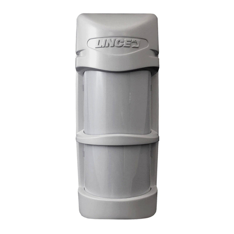
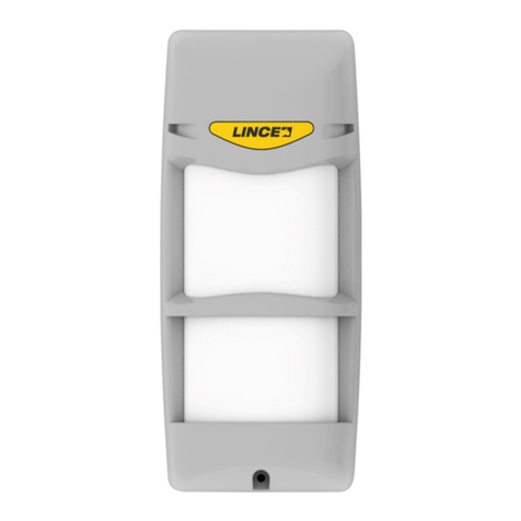
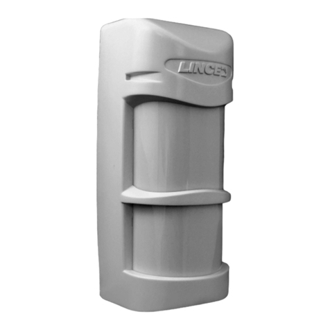
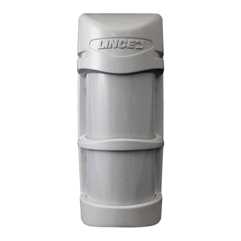
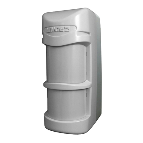
Il rilevatore da esterno a tenda 1908-BOBBY-AM-T è composto
da 2 sensori passivi dual PIR ed una microonda. L’elettronica
particolarmente evoluta è stata progettata per garantire le
massime prestazioni in ambiente esterno e a temperature rigide.
Ruotando il meccanismo interno è possibile ottenere tre aree
di copertura, ognuna di 5° e mediante il posizionamento della
mascherina sulla lente, è possibile selezionare una o più di una.
L’infrarosso inferiore è orientabile anche verticalmente e questo
permette di ottenere un range compreso tra 3 m e 10 m.
I tre sensori, gestiti da un microcontrollore, possono essere
combinati tra loro a seconda delle esigenze di installazione (triplo
AND, MW in AND con ogni PIR, AND dei PIR con MW esclusa,
triplo OR). Se settato in triplo AND permette la discriminazione
degli animali (PET IMMUNITY)
Nelle versioni (1908-BOBBY-AM-T e 1907-BOBBY-AM-T-E)
dotate di antimascheramento ad infrarossi attivi (EN 50131-
1), la funzione è stata implementata per rendere il rilevatore
inattaccabile da quanti potrebbero avere accesso al sito dove
è installato durante il periodo in cui il sistema risulta disinserito.
Il rilevatore segnala in questo modo, ogni tentativo di impedirne
il funzionamento bloccando (mascherando) il suo campo di
rilevazione. Il ssaggio del rilevatore può essere sia a parete che
su palo (altezza 1 ÷ 1,2 m).
1. INTRODUZIONE................................................................................................ 2
1.1 CARATTERISTICHE GENERALI ........................................................... 3
1.2 CARATTERISTICHE TECNICHE........................................................... 3
1.3 CONTENUTO DELLA CONFEZIONE .................................................... 3
1.4 IDENTIFICAZIONE DELLE PARTI......................................................... 4
2. INSTALLAZIONE............................................................................................... 5
2.1 AVVERTENZE GENERALI..................................................................... 5
2.2 MONTAGGIO DEL RILEVATORE .......................................................... 5
2.3 COLLEGAMENTI ELETTRICI................................................................ 8
2.4 CONFIGURAZIONE DEL RILEVATORE................................................ 8
2.4.1 Descrizione dei LED.................................................................... 8
2.4.2 Regolazione portata della microonda.......................................... 9
2.4.3 Congurazione dei DIP-switch .................................................... 9
2.4.4 Regolazione PIR 2 ................................................................... 10
2.4.5 Funzionamento in AND ............................................................. 12
2.4.6 Antimascheramento .................................................................. 13
3. AREA DI COPERTURA................................................................................... 13
3.1 CONFIGURAZIONE 1 - FASCIO SINISTRO........................................ 14
3.2 CONFIGURAZIONE 2 - FASCI SINISTRO E CENTRALE................... 15
3.3 CONFIGURAZIONE 3 - FASCIO CENTRALE ..................................... 15
3.4 CONFIGURAZIONE 4 - FASCI DESTRO E CENTRALE..................... 16
3.5 CONFIGURAZIONE 5 - FASCIO DESTRO ......................................... 16
4. ACCESSORI DISPONIBILI ............................................................................. 17
4.1 STAFFA ................................................................................................ 17
4.2 COVER PARAPIOGGIA ....................................................................... 17
4.3 KIT RISCALDATORE ........................................................................... 17
5. RICERCA DEI GUASTI E/O MALFUNZIONAMENTI .................................... 18
6. MANUTENZIONE E VERIFICHE PERIODICHE ............................................. 19
7. SMALTIMENTO E ROTTAMAZIONE.............................................................. 19
- Translation of the original instructions (original instructions in Italian) -
CONTENTS
1. INTRODUCTION ............................................................................................... 2
1.1 GENERAL FEATURES .......................................................................... 3
1.2 TECHNICAL FEATURES ....................................................................... 3
1.3 PACKAGING CONTENTS...................................................................... 3
1.4 PARTS IDENTIFICATION....................................................................... 4
2. INSTALLATION ................................................................................................. 5
2.1 GENERAL PRECAUTIONS ................................................................... 5
2.2 INSTALLING THE DETECTOR.............................................................. 5
2.3 DETECTOR WIRING ............................................................................ 8
2.4 DETECTOR SET-UP.............................................................................. 8
2.4.1 LEDs description ......................................................................... 8
2.4.2 MW range adjustment ................................................................. 9
2.4.3 DIP-switches conguration.......................................................... 9
2.4.4 PIR 2 adjustment....................................................................... 10
2.4.5 AND mode operation................................................................. 12
2.4.6 Antimasking............................................................................... 13
3. COVERAGE AREA.......................................................................................... 13
3.1 CONFIGURATION 1 - LEFT BEAM .................................................... 14
3.2 CONFIGURATION 2 - LEFT AND CENTRAL BEAMS......................... 15
3.3 CONFIGURATION 3 - CENTRAL BEAM.............................................. 15
3.4 CONFIGURATION 4 - RIGHT AND CENTRALE BEAMS.................... 16
3.5 CONFIGURAZION 5 - RIGHT BEAM................................................... 16
4. AVAILABLE ACCESSORIES .......................................................................... 11
4.1 BRACKET............................................................................................. 11
4.2 RAIN COVER ....................................................................................... 11
4.3 HEATER KIT......................................................................................... 11
5. TROUBLE SHOOTING ................................................................................... 18
6. MAINTENANCE AND PERIODIC CHECKS ................................................... 19
7. DISPOSAL AND SCRAPPING........................................................................ 19
1. DESCRIPTION
The outdoor curtain detector 1908-BOBBY-AM-T is composed
by two dual PIR passive infrared sensors and one microwave.
The advance electronic of the detector has been designed and
built to ensure maximum performance in outdoor environment
and in cold temperatures. By turning the internal mechanism,
it is possible to obtain three coverage areas, each of 5° and,
by placing a mask on the lens, it is possible to select one of
them or more than one. The lower infrared beam, also vertically
adjustable, allows to obtain a range of coverage between a
minimum of 3 m and a maximum of 10 m.
The three sensors, managed by a microcontroller, can be
combined with each other depending on the installation
requirements (triple AND, MW AND with each PIR, AND of
PIR with MW excluded, triple OR). If set in triple AND allows
discrimination of animals (PET IMMUNITY).
In the versions provided with anti-masking (1908-BOBBY-AM-T
and 1907-BOBBY-AM-T-E), the function has been designed to
make the detector immune to those who may have access to the
site where it is installed during the period in which the system
is switched off. In this way, the detector signals any attempt to
prevent its operation masking its detection eld. The xing of the
detector can be either on the wall or on a pole (height from 1 to
1.2 m).
Le informazioni riportate in questo manuale sono state compilate con
cura, tuttavia LINCE ITALIA S.p.A. non può essere ritenuta responsabile
per eventuali errori e/o omissioni. LINCE ITALIA S.p.A. si riserva il diritto
di apportare in ogni momento e senza preavviso, miglioramenti e/o
modiche ai prodotti descritti nel presente manuale. Consultare il sito
www.LINCE.net per le condizioni di assistenza e garanzia. LINCE ITALIA
S.p.A. pone particolare attenzione al rispetto dell’ambiente. Tutti i prodotti
ed i processi produttivi sono progettati con criteri di eco-compatibilità.
Il presente articolo è stato prodotto in Italia.
• L’aziendahaunsistemadigestionedellaqualitàcerticatosecondola
norma ISO 9001:2015 (n° 4796 - A)
• L’aziendahaunsistemadigestioneambientalecerticatosecondola
norma ISO 14001:2015 (n° 4796 - E)
• L’azienda ha un sistema di gestione della salute e sicurezza sul lavoro
certicatosecondolanormaBSOHSAS18001:2007(n°4796-I)
The information in this manual has been issued with care, but LINCE
ITALIA S.p.A. will not be responsible for any errors or omissions. LINCE
ITALIA S.p.A. reserves the right to improve or modify the products
described in this manual at any time and without advance notice.Terms
and conditions regarding assistance and the product warranty can be
found at LINCE ITALIA’s website www.lince.net. LINCE ITALIA S.p.A.
makes it a priority to respect the environment. All products and production
processes are designed to be eco-friendly and sustainable.
This product has been Made in Italy.
• Thecompanyhasacertiedsystemofqualitymanagementaccording
to ISO 9001:2015 (n° 4796 - A) standard.
• The company has a certied system of environmental management
according to ISO 14001:2015 (n° 4796 - E) standard.
• The company has a certied system of health and work security
managementaccordingtoBSOHSAS18001:2007(n°4796-I)standard.
