Theben TIMEGUARD UDSS2PIR User manual
LED Ready PIR
Up/Down Light
Model: UDSS2PIR
(Silver Finish)
Model: UDB2PIR
(Black Finish)
I n s t a llation & Ope r ating Instruction s

1. General Information
These instructions should be read carefully and retained for
further reference and maintenance.
Timeguard reserve the right to alter these instructions
at any time. Up to date instructions will always be available
for download at www.timeguard.com
2. Safety
• Before installation or maintenance, ensure the mains supply
to the luminaire is switched off and the circuit supply fuses
are removed or the circuit breaker turned off.
• It is recommended that a qualified electrician is consulted or
used for the installation of this luminaire and install in
accordance with the current IEE wiring and Building
Regulations.
• Check that the total load on the circuit including when this
luminaire is fitted does not exceed the rating of the circuit
cable, fuse or circuit breaker.
• To clean use a clean dry cloth only. Do not use liquid cleaners.
3. Technical Specifications
• Class Protection: Class I
Note:
• IP Rating: IP44
• Operating Temperature: 0˚to 40˚C
• PIR Switching Capacity: x2 35W Halogen or
x2 15W LED
• Mains Suppply: 220-240V AC 50Hz
1
• PIR Detection Range: 4 - 7m at a 2m
mounting height
(adjustable)
• Dectection Angle:
• Time ON Adjustment:
• (LUX) level adjustment: 10 - 2000
• Manual Override: Yes
• Construction: Stainless steel
• Dimensions (H x W x D): 221mm x 60mm x 100mm
90˚ (Fixed)
10 seconds - 5 minutes
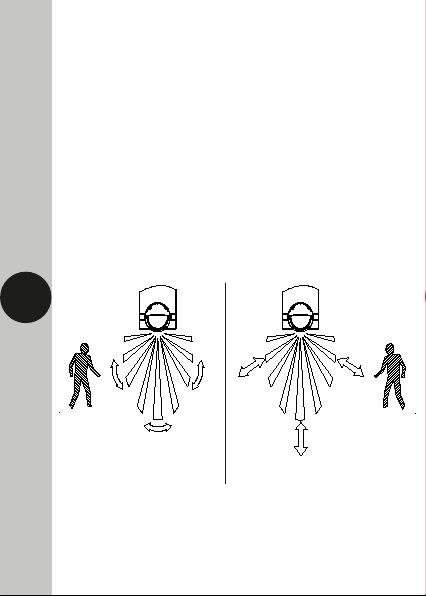
4. Selecting a location
2
• The PIR has a number of detection zones at various horizontal
and vertical angles as shown below.
• A moving human body or object needs to cross one of these
zones to activate the sensor. The optimum height for this is
between 1.5m - 2m mouting height. Careful positioning of
the luminaire is required to ensure the best performance from
the PIR and the appointed approach path.
Effective Approach Path
(ACROSS)
Ineffective Approach Path
(TOWARDS)

• Ensure the mains supply is switched off and the circuit
supply fuses are removed or the circuit breaker turned off.
•An isolating switch should be installed to enable the power
to be switched ON and OFF to the luminaire. This allows the
unit to be easily switched OFF for maintenance purposes.
3
5. Installation
•Remove the wall plate from the light fitting, by removing the
two nuts.
• Avoid positioning the luminaire near any sources of heat in
and around the detection area such as extractor fans,
tumble dryers or boiler exhauhsts etc. This would also include
other light sources such as secuirty lights.
•Reflective surfaces (i.e. pools of water, white painted walls,
overhanging branches and other types of foliage) may cause
false activation under heightened weather conditions.
•During extreme weather conditions the PIR may exhibit
unusual behaviour. Once normal weather resumes, the PIR
will carryout normal operations.

•Mark the position of the mouting holes on the wall using
the wall plate as a template.
• Drill the holes for the wall plugs ensuring not to infringe on
any gas/water pipes or electrical cables that may be hidden
below/behind the surface.
• Pass through the mains supply cable into the wall plate via
the grommet/cable grand ensuring there is a tight grip on
the cable to maintain the IP rating of the luminaire.
•Mount the wall plate to the wall, using the fittings provided.
•Connect the mains supply to the revelant terminals ensuring
the correct polarity is observed and that all bare conductors
are sleeved (see section 5. Connection Diagram).
4

5
•Replace the luminaire over the wall plate, ensuring the
gasket is in place, and tighten the two nuts hand tight,
to secure the fitting.
6.Connection Diagram
•Connect the 230V AC 50Hz mains supply cable as follows;
Isolation
Switch
Brown or Red
Blue or Black
Note that the earth terminal is attached directly to the fitting.
This is to ground the metalic exterior of the luminaire.

7.Commisioning and Operation
• Restore the power from the mains supply breaker or
isolating switch and test for the correct operation.
• Adjust the time dial (fully anti-clockwise), and the Lux
dial should be set to the minimum for daylight/night
operation for the purpose of the walk test.
• Allow the PIR on the luminaire to settle down if the unit is
switched on currently, this is called warm up mode.
• Once the unit is in the OFF position walk across the
detection area, when the PIR is triggered and the lamp will
turn ON for the minimum set amount of time.
• Once you are happy with the pickup area of the PIR you
can set the Lux dial in the clockwise direction to trigger
when dusk is approaching. (This may be best performed in
real time in the evening subject to the users preferance).
• You can also adjust the middle dial which will vary the
sensitivity/range of the pickup area of up to 7m.
Walk Test Procedure
+++
_
__
PIR Controls
Time Delay Dial
Adjustment Level
(Reference)
Lux Dial
(Dusk/Dawn)
Adjustment Level
(Reference)
Sensitivity/Range
Dial Adjustment
Level (Reference)
Lux Dial
(Dusk/Dawn)
Sensitivity/Range
Dial
Time Delay Dial
Note: the sensitivity of the dials can vary slightly
6

8.Manual Override
• The luminaire can be switched on for longer peroids via the
use of the manual override mode. This can be activated by
using the internal wall switch. Switch the internal wall
switch once OFF/ON within 2 seconds.
• The luminaire will continuously light for 6 hours, until the
fitting is set back to auto mode. To return to auto mode,
switch the internal wall switch OFF/ON again within 2
seconds.
• The unit will return to auto mode and now operate as
setup after the walk test procedure.
7
1.5 - 2.0M
7M
3M 5M
appro.90°
Detection Area
9. Troubleshooting Guide
Problem Cause/Solution
The luminaire does
not switch on when
in the detection area.
Bulb faulty or missing.
Nearby light sources causing interference.
Redirect the PIR or light source if possible.

3 Year Guarantee
In the unlikely event of this product becoming faulty due
to defective material or manufacture, within 3 years of the
date of purchase, please return it to your supplier with
proof of purchase and it will be replaced free of charge.
For years 2 to 3 or with any difficulty in the first year,
telephone our helpline. Note: a proof of purchase is
required in all cases. For all eligible replacements
(where agreed by Timeguard),
the customer is responsible for all
shipping/postage charges outside
of the UK. All shipping costs are
to be paid in advance before a
replacement is sent.
8
Problem Cause/Solution
False activation.
(Luminaire switches
on for no apparent
reason)
Heat sources as described in section 4.
Reflective surfaces described in section 4.
Moving pedestrians, cars or animals in
the area. Check the detection area.
Nearby electromagnetic disturbance from
a neighbouring circuit (CCTV interference).
Luminaire remains
switched on
Continuous false activation resetting the
delay time when an object is detected.
Luminaire switches on
during daylight hours
Shadow casting over the PIR sensor
Clouds creating a dark presence.
Enure the luminaire recievces adequate
daylight from all angles (not covered).

If you experience problems, do not immediately
return the unit to the store.
Email the Timeguard Customer Helpline:
HELPLINE
helpline@timeguard.com
or call the helpdesk on 020 8450 0515
Qualified Customer Support Coordinators will be online
to assist in resolving your query.
For a product brouchure please contact:
Timeguard Limited.
Victory Park 400 Edgware Road,
London NW2 6ND
Sales Office: 02084521112
www.timeguard.com
67.058.682 (Issue 1)
T.W - May 2021
This manual suits for next models
1
Table of contents
Other Theben Lighting Equipment manuals


