Themis A220 User manual

User Manual
User Manual
A220
A220
Installation
Manual
Installation
Manual
Data Storage Appliance

A220 Data Storage Appliance

Themis Computer
P/N 118610-024 QuickStart Guide
QS-1
Before YouStart
Make sure that all site and network requirements have
been satisfied before installing the A220 Data Storage
Appliance system.
Site Requirements
• Two persons to lift the A220 Data Storage Appliance
system.
• Box cutter or sharp knife.
• Phillips screwdriver to install the system in a rack.
• Laptop or PC with Internet access.
• Three Ethernet cables—bulk Category (Cat) 5 for IP
connectivity to your network [cables are not shipped
with the initial A220 order].
• For high availability, at least two 110-volt or 220-volt
AC circuits.
1BEFORE YOU START
Network Requirements
• Three 1-Gb Ethernet connections—one for system
management, and two for system management / data
transfer.
• A DHCP (Dynamic Host Configuration Protocol)
server for network access.
•Recommended: A Network Windows Domain con-
troller (required for Windows shares).
QuickStart A220 Data Storage
Appliance

Themis Computer
A220 Data Storage Appliance QuickStart Guide
QS-2
Figure 1. Remove All Items from the Shipping Container.
AThe A220 Data Storage Appliance (Front View).
BThe A220 Data Storage Appliance (Rear View).
2 AC Power Cords
A220 Data Storage Appliance QuickStart Guide
Switch
POWER-ON
Hole
1 Unpack
What you need: Box cutter or sharp knife.
Instructions: A220 Data Storage Appliance Installation
Manual.
Open the A220 shipping container with a box cutter or
sharp knife, carefully avoiding the enclosed contents.
More detailed information concerning the A220 Data
Storage Appliance can be obtained from the A220 Data
Storage Appliance Installation Manual, which can be ac-
cessed online at http://themis.com/themis/manuals. Ob-
tain the website password from your A220 vendor.
Each shipping package contains the following items:
1. An A220 Data Storage Appliance (see Figure 1).
2. Two AC power cords.
3. A220 Data Storage Appliance QuickStart Guide (this
manual).
4. An optional pair of rack-mount slides may be included
in your order, but will be shipped separately.
1UNPACK

Themis Computer
A220 Data Storage Appliance QuickStart Guide
QS-3
What you need: Phillips screwdriver.
Instructions: A220 Data Storage Appliance Installation
Manual.
Using the A220 Data Storage Appliance Installation Man-
ual, install the component hardware. If you have ordered
the optional rack-mount brackets with handles and/or op-
tional rack-mount slide kits, install these now.
• If applicable, replace the rack-mount brackets without
handles with rack-mount brackets with handles.
•Installoptional rack-mount slides onto the rack and
both sides of the A220 chassis (see A220 Data Stor-
age Appliance Installation Manual for details).
• Slide and secure the A220 chassis inside the rack. You
may need assistance in lifting and guiding the chassis.
Install all Cables
Install all I/O and accessory cables and power cords to
the A220 rear panel connectors in the following order:
1. Connect a Cat-5 Ethernet cable to the LAN 1 port (see
Figure 2) and another cable to the LAN 2 port.
2 RACK & CABLE
2. Connect a Cat-5 Ethernet cable to the BMC port.
3. Alternative Method to BMC or LAN1/LAN2 Connec-
tion—Connect a monitor and keyboard to their re-
spective I/O ports (see Figure 2).
4. If applicable, plug the AC Power cord from the monitor
into a “live” AC circuit.
5. Plug an AC Power cord into the PS1 power supply and
another cord into the PS2 power supply.
Figure 2. Connect All Cables and AC Cords to the Rear Panel.
LAN 1
LAN 2
PS1 PS2
Power Supplies BMC
Note: BMC = Baseboard Management Controller
VGA
Keyboard
Monitor
AC Power

Themis Computer
A220 Data Storage Appliance QuickStart Guide
QS-4
Plug the AC Power cords from power supplies PS1 and
PS2 into “live” AC sources. This will cause each power
supply LED to light (green). On the front of the A220, stick
an unbent paper clip or meter probe into the POWER-ON
switch hole (see Figure 1A, page QS-2) momentarily, af-
ter which the POWER LED will light (green) and the sys-
tem will turn ON and start to boot the Open-E Data
Storage operating system.
After the system has completed booting, an interpretation
of how the system is operating can be read from the five
LEDs on the front of the A220 (see Figure 3 and Table 1).
Note that LED Aindicates activity on the solid-state boot
drive, which is attached directly to the A220 Motherboard.
The ten (10) drive canisters (each canister contains two
drives) that are accessed through the front of the system
have LEDs directly associated with drive operation (these
are described in Figure 4).
3 POWER ON SYSTEM
Figure 3. LEDs on the A220 Data Storage Appliance Front Panel
BAC DE
Table 1. Front-Panel LED Definitions
LED Definition Description (when LED is ON)
ABoot drive (Motherboard attached) ●Indicates boot drive activity
BPower failure (Left Power Supply) ●Indicates left power supply failure
CPower failure (Right Power Supply) ●Indicates right power supply failure
DOverheat / Fan Fail ●Warns that the system is exceeding
specified temperature parameters
EPower ●Indicates that system is turned ON
Figure 4. LEDs on the A220 Data Storage Appliance Drive Canisters
Drive Lock
Pushbutton
Drive Release
Drive Door
Rivet
Air Vents
Activity LED
Status LED
Air Vents
= Top 2 LEDs are associated with Rear Drive
= Bottom 2 LEDs are associated with Front Drive
2 Righthand LEDs = Drive Status
2 Lefthand LEDs = Drive Activity

Themis Computer
A220 Data Storage Appliance QuickStart Guide
QS-5
Before starting:
• Make sure that the A220 is booted and the Power LED
(see Figure 3 and Table 1 on page QS-4) is ON.
Note: The A220 system is shipped with IP address con-
figurations already assigned to each of the three Ethernet
ports (LAN 1, LAN 2, and BMC). If the assigned address-
es are acceptable to the user, this section (4—CONFIG-
URE) may be skipped; in which case, go directly to
section 5—SETUP AS SHIPPED on page QS-6.
Ethernet Configuration
There are three different methods to chose from to con-
figure IP addresses:
1. Attach a keyboard and monitor directly to the A220 to
assign an IP address to Ethernet port 1 (LAN 1)
and/or Ethernet port 2 (LAN 2).
2. Assign an IP address by logging onto the BMC port.
3. Assign an IP address by logging onto Ethernet port 1
(LAN 1) and/or Ethernet port 2 (LAN 2), which is al-
ready set to DHCP (see section 5—SETUP AS
SHIPPED—on page QS-6).
4 CONFIGURE
Method 1—Keyboard and Monitor
Step 1—Only initially, a keyboard and monitor must be at-
tached to the appropriate connectors on the A220 (see
Figure 2 on page QS-3).
Step 2—Next, press <F1> to bring up the main menu.
Step 3—Then press <Alt><Ctrl><N> to bring up the Net-
work Setting Menu.
Step 4—Assign an IP address to Ethernet port 1 (LAN 1)
and/or Ethernet port 2 (LAN 2) based on their network
setup. [See section 6—PASSWORDS on page QS-7.]
Step 5—Open a web browser with the assigned IP ad-
dress for further management and setup.
Step 6—Finally, remove the keyboard and monitor.
Method 2—BMC Port
Use the following method to configure the BMC port:
1. Log onto the BMC port, which is set to DHCP (use the
MAC address printed on the adjoining label; see Fig-
ure 5 on page QS-6).
After you have configured the BMC port, follow these
steps [See section 6—PASSWORDS on page QS-7.]:
Step 1—Using a laptop computer connected to the BMC
port, open a web browser using the assigned IP address.

Themis Computer
A220 Data Storage Appliance QuickStart Guide
QS-6
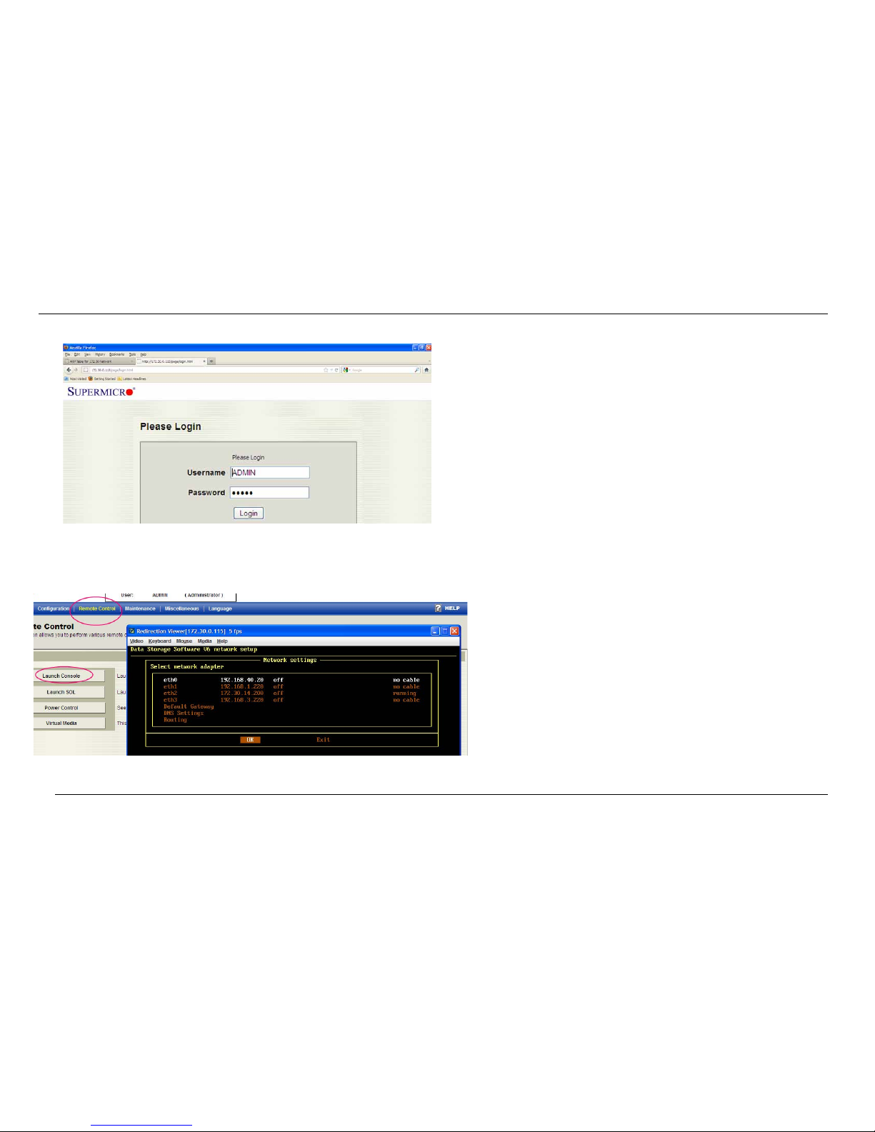
Step 2—Open a Console from the BMC remote-control
web page (see Figure 6).
Figure 5. Log Onto the BMC Port
Figure 6. Open a Console from the BMC Remote-
Control Web Page
Step 3—Press <F1> to bring up the main menu.
Step 4—Press <Alt><Ctrl><N> to bring up the Network
Setting Menu.
Step 5—Assign an IP address to Ethernet port 1 (LAN 1)
and/or Ethernet port 2 (LAN 2) based on their network
setup.
Step 6—Open a web browser with the assigned IP ad-
dress for further management and setup.
Method 3—Ethernet Port 1 and/or Port 2
Use the following method to configure the Ethernet ports:
1. Log-in to Ethernet port 1(LAN 1) with a Static IP ad-
dress such as 192.168.2.2/24, and/or log-in to Ether-
net port 2 (LAN 2), which is set to DHCP (use the MAC
address printed on the adjoining label)
2. Configure both ports based on their network require-
ments
[See section 6—PASSWORDS on page QS-7.]
Step 1—Open a web browser with the assigned IP ad-
dress for further management and setup.

Themis Computer
A220 Data Storage Appliance QuickStart Guide
QS-7
When shipped, your A220 system will have the following
IP address configurations:
• The BMC port is configured as a DHCP with a MAC
address as defined on the adjoining label
• Ethernet port 1 (LAN 1) is assigned the following Static
IP address = 192.168.2.2/24
• Ethernet port 2 (LAN 2) is configured through DCHP
(using the MAC address defined on the adjoining
label)
[See section 6—PASSWORDS.]
5 SETUP AS SHIPPED
Throughout
Throughout the A220 configuration process, you will be
required to enter a USER ID followed by a PASSWORD.
These are displayed as followed (all characters are case-
sensitive):
Prompt User ID Password
Open-E Full Access1.........................admin
BMC ADMIN.................................ADMIN
RAID admin......................................0000
____________________
1—The user ID “Full Access” appears automatically at
the prompt after the system has booted.
6 PASSWORDS

Themis Computer
A220 Data Storage Appliance QuickStart Guide
QS-8

Themis Computer—Rest of World
5 Rue Irene Joliot-Curie
38320 Eybens, France
Phone +33 476 14 77 80
Fax +33 476 14 77 89
Themis Computer—Americas and Pacific Rim
47200 Bayside Parkway
Fremont, CA 94538
Phone (510) 252-0870
Fax (510) 490-5529
World Wide Web http://www.themis.com
A220DataStorageAppliance
InstallationManual
Version 1.0—April 2012

Copyright © 2012 Themis Computer, Inc.
ALL RIGHTS RESERVED. No part of this publication may be reproduced in any form, by
photocopy, microfilm, retrieval system, or by any other means now known or hereafter invented without
the prior written permission of Themis Computer.
The information in this publication has been carefully checked and is believed to be accurate. However,
Themis Computer assumes no responsibility for inaccuracies. Themis Computer retains the right to
make changes to this publication at any time without prior notice. Themis Computer does not assume
any liability arising from the application or use of this publication or the product(s) described herein.
RESTRICTED RIGHTS LEGEND: Use, duplication, or disclosure by the United States Government
is subject to the restrictions set forth in DFARS 252.227-7013 (c)(1)(ii) and FAR 52.227-19.
TRADEMARKS and SERVICEMARKS
Themis®is a registered trademark of Themis Computer, Inc.
Intel® and Xeon® are registered trademarks of Intel Corporation.
Red Hat®is a registered trademark of Red Hat, Inc.
Linux®is a registered trademark of Linus Torvalds.
SuperMicro®is a registered trademark of Super Micro Computer, Inc.
All other trademarks, servicemarks, or registered trademarks used in this publication are the property of
their respective owners.
CE Marking
This product complies with the European EMC Directive (2004/108/EC) and the European Low Voltage
Safety Directive (2006/95/EC)/.
Safety Precautions
Instructions regarding safety precautions during installation, operation, or maintenance of the equipment
are given in the section entitled “Safety Instructions” on page -iv.
WARNINGS and CAUTIONS
The definitions of WARNINGS and CAUTIONS as used in this document are given in the Preface in
the section entitled “Notes, Cautions, Warnings, and Sidebars”.
A220 Data Storage Appliance Installation Manual, Version 1.0
April 2012
Part Number: 118971-024
Themis Customer Support
North America, South America, and Pacific Rim
Telephone: 510-252-0870
Fax: 510-490-5529
E-mail: [email protected]
Web Site: http://www.themis.com

iii
Themis Computer
VersionRevisionHistory
Version 1.0 .....................................................................................April 2012

iv Themis Computer
A220 Data Storage Appliance Installation Manual Version 1.0
Safety Instructions
To maximize user safety and ensure correct device operation, all instructions con-
tained in this section should be read carefully.
• The device must be used in accordance with the instructions for use.
• Electrical installations in the room must correspond to the requirements of
respective regulations.
• Take care that there are no cables, particularly mains cables, in areas where
persons can trip over them.
• Do not use a mains connection in sockets shared by a number of other power
consumers. Do not use an extension cable.
• Only use the mains cable supplied.
• The unit is completely disconnected from the power source only when the
power cord is disconnected from the power source. Therefore the power cord
and its connectors must always remain easily accessible.
• Do not set up the device in the proximity of heat sources or in a damp location.
Make sure the device has adequate ventilation.
• All plugs on the connection cables must be screwed or locked to the chassis
housing.
• The device is designed to be used in horizontal position only.
• The device is no longer safe to operate when
— the device has visible damage or
— the device no longer functions.
• In these cases, the device must be shut down and secured against unintentional
operation.
• Repairs may only be carried out by a person authorized by Themis Computer.
• The device may only be opened for the installation and removal of extension
(PCI) cards, memory modules, storage drives, fan housings, power supplies
Caution: It is important that the user observe all warnings and instructions
that are on the device and contained in this manual.

v
Themis Computer
Safety Instructions
(RES-22 and RES-22 systems only), and the lithium battery—all in accordance
with the instructions given in this manual.
• If extensions are made to the device, the legal stipulations and the device spec-
ifications must be observed.
• The device must be switched off when removing the top cover; for example,
before installing extension (PCI) cards.
Operation of Laser Source Devices
DVD/CD-ROM drives contain laser light-emitting diodes (classified in accordance
with IEC 825-1:1993: LASER CLASS 1) and, therefore, must not be opened.
If the enclosure of such a drive is opened, invisible laser radiation is emitted. Do
not allow yourself to be exposed to this radiation.
The laser system meets the code of Federal Regulations 21 CFR,1040 for the USA
and Canadian Radiation Emitting Devices Act, REDR C 1370.
Electrostatic Discharge (ESD)
A sudden discharge of electrostatic electricity can destroy static-sensitive devices
or micro-circuitry. Proper packaging and grounding techniques are necessary pre-
cautions to prevent damage. Always take the following precautions:
1. Transport boards in static-safe containers such as boxes or bags.
2. Keep electrostatic-sensitive parts in their containers until they arrive at static-
free stations.
3. Always be properly grounded when touching a sensitive board, component, or
assembly.
4. Store electrostatic-sensitive boards in protective packaging or on conductive
foam.
Grounding Methods
Guard against electrostatic damage at workstations by following these steps:
1. Cover workstations with approved anti-static material. Provide a wrist strap
connected to a work surface and properly grounded tools and equipment.

vi Themis Computer
A220 Data Storage Appliance Installation Manual Version 1.0
2. Use anti-static mats, heel straps, or air ionizers to give added protection.
3. Handle electrostatic-sensitive components, boards, and assemblies by the case
or the PCB edge.
4. Avoid contact with pins, leads, or circuitry.
5. Turn off power and input signals before inserting and removing connectors or
test equipment.
6. Keep the work area free of non-conductive materials such as ordinary plastic as-
sembly aids and Styrofoam.
7. Use field service tools, such as cutters, screwdrivers, and vacuums that are con-
ductive.
8. Always place drives and boards PCB-assembly-side down on the foam.
Instructions for the Lithium Battery
RES systems are equipped with a lithium battery installed on the motherboard. To
replace this battery, please observe the instructions that are described in this man-
ual.
Warning: There is a danger of explosion when the wrong type of battery is used
as a replacement.

vii
Themis Computer
Table of Contents
QuickStart ..................................................................................................................QS-1
Safety Instructions .......................................................................................................... iv
Preface ............................................................................................................................ xiii
1. Overview and Specifications ........................................................................................ 1-1
1.1 Overview ................................................................................................................ 1-1
1.2 System LEDs and I/O Connectors ......................................................................... 1-5
1.3 Special Features ..................................................................................................... 1-9
1.3.1 Recovery from AC Power Loss .................................................................1-9
1.4 PC Health Monitoring ............................................................................................ 1-9
1.4.1 Fan Status Monitor with Firmware Control ............................................. 1-10
1.4.2 Environmental Temperature Control .......................................................1-10
1.4.3 Wake-On-LAN (WOL) ............................................................................ 1-10
1.5 Specifications ....................................................................................................... 1-12
1.5.1 General ..................................................................................................... 1-12
1.5.2 Electrical .................................................................................................. 1-13
1.5.2.1 System Power ........................................................................... 1-13
1.5.2.2 Output Voltage .......................................................................... 1-14
1.5.3 Environmental .......................................................................................... 1-14
1.5.3.1 Shock ........................................................................................ 1-14
1.5.3.2 Electrostatic Discharge ............................................................. 1-14
1.5.3.3 Noise ......................................................................................... 1-14
1.6 Packaging and Shipping ....................................................................................... 1-15
1.6.1 Accessory Kit ........................................................................................... 1-15
1.6.2 Rack-Mount Slides (Optional) ................................................................. 1-16
2. Installation and Operation ........................................................................................... 2-1
2.1 Rack Mounts .......................................................................................................... 2-1
2.1.1 Mounting Brackets ..................................................................................... 2-1
2.1.2 Rack-Mount Slides (Optional) ................................................................... 2-1

viii Themis Computer
A220 Data Storage Appliance Installation Manual Version 1.0
2.2 Operation ............................................................................................................... 2-3
2.2.1 Plug in the AC Power Cords and Start the System .................................... 2-3
2.2.2 Before You Start ........................................................................................ 2-4
2.2.3 Turning the System Off .............................................................................2-6
2.3 Installation Procedures ........................................................................................... 2-7
2.3.1 Remove Protective Top Cover ................................................................... 2-7
2.3.2 Memory Modules ....................................................................................... 2-9
2.3.2.1 Replacement .............................................................................. 2-10
2.3.3 PCI Cards ................................................................................................. 2-12
2.3.3.1 Replacing Cards ........................................................................ 2-12
2.3.4 Lithium Battery ........................................................................................ 2-13
2.3.4.1 Removing the Lithium Battery ................................................. 2-13
2.3.4.2 Installing a Lithium Battery ...................................................... 2-13
2.3.5 SATA 2 Storage Drive ............................................................................. 2-14
2.3.5.1 Storage-Drive Removal ............................................................ 2-14
2.3.5.2 Canister Installation .................................................................. 2-17
2.3.6 Removable 80-mm Fan ............................................................................ 2-17
2.3.6.1 Removing and Installing an 80-mm Fan ................................... 2-17
2.3.7 Power Supply ........................................................................................... 2-18
2.3.7.1 Removing a Power Supply ....................................................... 2-18
2.3.7.2 Installing a Power Supply ......................................................... 2-19
Appendix A. Connector Pinouts ...................................................................................... A-1
A.1 PS/2 Keyboard (Mouse is Not Supported) ........................................................... A-1
A.2 USB Ports ............................................................................................................. A-2
A.3 Serial Port (Not Supported) .................................................................................. A-2
A.4 Super VGA Monitor Port ...................................................................................... A-3
A.5 Gigabit Ethernet LAN Ports ................................................................................. A-4
A.6 IPMI Dedicated LAN Port .................................................................................... A-4
Appendix B. Rack-Mount Slide Installation ...................................................................B-1
Appendix C. Re-packaging Instructions .........................................................................C-1
C.1 Re-packaging for Shipment ...................................................................................C-1
C.2 Packaging Components ..........................................................................................C-2
C.3 Instructions for Re-packaging ................................................................................C-3

ix
Themis Computer
Table of Contents
Index ..............................................................................................................................Index-1
Reader Comment Card

xThemis Computer
A220 Data Storage Appliance Installation Manual Version 1.0
Table of contents