Themis TGA-7000 PMC User manual

Themis Computer—Rest of World
5 Rue Irene Joliot-Curie
38320 Eybens, France
Phone +33 476 14 77 80
Fax +33 476 14 77 89
Themis Computer—Americas and Pacific Rim
47200 Bayside Parkway
Fremont, CA 94538
Phone (510) 252-0870
Fax (510) 490-5529
World Wide Web http://www.themis.com
TGA-7000 PMC Graphics Card
Installation Guide
Version 1.0— December 2005

Copyright © 2005 Themis Computer, Inc.
ALL RIGHTS RESERVED. No part of this publication may be reproduced in any form, by
photocopy, microfilm, retrieval system, or by any other means now known or hereafter invented without
the prior written permission of Themis Computer.
The information in this publication has been carefully checked and is believed to be accurate. However,
Themis Computer assumes no responsibility for inaccuracies. Themis Computer retains the right to
make changes to this publication at any time without prior notice. Themis Computer does not assume
any liability arising from the application or use of this publication or the product(s) described herein.
RESTRICTED RIGHTS LEGEND: Use, duplication, or disclosure by the United States Government
is subject to the restrictions set forth in DFARS 252.227-7013 (c)(1)(ii) and FAR 52.227-19.
TRADEMARKS
THEMIS®is a registered trademark of Themis Computer, Inc.
SOLARIS™is a trademark of Sun Microsystems
SPARC® and UltraSPARC®are registered trademarks of SPARC International
All other trademarks or registered trademarks used in this publication are the property of their
respective owners.
TGA-7000 PMC Graphics Card Installation Guide, Version 1.0
December 2005
Part Number: 112874-021
Themis Customer Support
North America, South America, and Pacific Rim
Telephone: 510-252-0870
Fax: 510-490-5529
E-mail: support@themis.com
Web Site: http://www.themis.com

iii
Themis Computer
TGA-7000 PMC Graphics Card Installation Guide
Version Revision History
Version 1.0...................................................................................December 2005

iv Themis Computer
TGA-7000 PMC Graphics Card Installation Guide

v
Themis Computer
Table of Contents
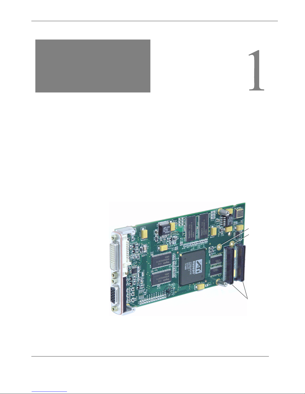
1. TGA-7000 Overview ..................................................................................................... 1-1
1.1 Features .................................................................................................................. 1-2
1.2 Video Formats ........................................................................................................ 1-2
1.2.1 Video Display Ports ................................................................................... 1-4
1.3 Technical Support .................................................................................................. 1-4
2. Hardware and Software Installation ........................................................................... 2-1
2.1 Hardware Installation ............................................................................................. 2-1
2.2 Software Installation .............................................................................................. 2-3
2.2.1 TGA-7000 Software Packages ................................................................... 2-3
2.2.1.1 Software Package Locations ....................................................... 2-3
2.2.1.2 Software Package Names ............................................................ 2-4
2.2.2 Solaris Operating System Patches ............................................................. 2-4
2.2.3 Sun OpenGL for Solaris Software ............................................................. 2-4
2.2.3.1 Sun OpenGL 1.3 for Solaris Patches .......................................... 2-5
2.3 Avoiding Colormap Flash ...................................................................................... 2-6
2.3.1 Using the -depth 24 Option ........................................................................ 2-6
2.3.2 Using the -fake8 Option ............................................................................. 2-6
2.4 TGA-7000 Default Console Display .................................................................... 2-7
2.5 Man Pages .............................................................................................................. 2-8
3. Configuring Multiple Frame Buffers .......................................................................... 3-1
3.1 Configuring Multiple Frame Buffers Through the Xservers File .......................... 3-1
3.2 Xinerama ................................................................................................................ 3-3
3.2.1 Using Xinerama ......................................................................................... 3-3
3.2.2 Restrictions When Using Xinerama .......................................................... 3-4
4. Using TGA-7000 Graphics Accelerator Features ...................................................... 4-1
4.1 Video Output Methods ........................................................................................... 4-1
4.2 Setting Up Video Output Methods ........................................................................ 4-1

vi Themis Computer
TGA-7000 PMC Graphics Card Installation Guide
4.2.1 Setting Up Single Video Output (Default) ................................................ 4-1
4.2.2 Setting Up Two Video Outputs Over One Large Frame Buffer ................ 4-2
4.2.3 Setting Up Two Independent Video Outputs ............................................. 4-3
4.2.4 Default Color Depth ................................................................................... 4-4
4.3 Checking Device Configuration ............................................................................ 4-4
A. TGA-7000 I/O Connector Pinouts .............................................................................. A-1
A.1 I/O Port Specifications .......................................................................................... A-1
A.2 HD15 Video Output Port ...................................................................................... A-2
A.3 DVI Video Output Port ......................................................................................... A-3
Index .............................................................................................................................. Index-1
Reader Comment Card

vii
Themis Computer
Table of Contents
List of Figures
Figure 1-1 TGA-7000 PMC Graphics Card ...................................................................... 1-1
Figure 2-1 Host System Board (USPIIe-USB) for the TGA-7000.................................... 2-2
Figure 2-2 TGA-7000 PMC Graphics Card ...................................................................... 2-2
Figure A-1 TGA-7000 PMC Graphics Card I/O Ports..................................................... A-1
Figure A-2 TGA-7000 PMC Graphics Card HD15 Connector Pinout ............................ A-2
Figure A-3 TGA-7000 PMC Graphics Card DVI Connector Pinout ............................... A-3
List of Tables
Table 1-1 TGA-7000 PMC Graphics Card HD15 Video Formats................................... 1-3
Table 1-2 TGA-7000 PMC Graphics Card Video Formats ............................................. 1-3
(DVI-A, DVI-D, and HD15)
Table 2-1 TGA-7000 PMC Graphics Card CD Directories............................................. 2-3
Table 2-2 Location of TGA-7000 Software Packages ..................................................... 2-3
Table 2-3 Solaris 8 and 9 Software Package Names........................................................ 2-4
Table 2-4 TGA-7000 for Solaris Software Patches ......................................................... 2-4
Table 2-5 Sun OpenGL 1.3 for Solaris Software Patches................................................ 2-5
Table A-1 TGA-7000 PMC Graphics Card HD15 Signal Descriptions .......................... A-2
Table A-2 TGA-7000 PMC Graphics Card DVI Signal Descriptions............................. A-3

viii Themis Computer
TGA-7000 PMC Graphics Card Installation Guide

1-1
Themis Computer
1
TGA-7000 Overview
The Themis TGA-7000 2D/3D graphics accelerator card (see Figure 1-1) is a 24-bit
high-resolution graphics frame buffer that is installed and runs on PMC-based sys-
tem platforms such as the Themis TA64 and TP32 single-board computers. It can
plug into either a +5-volt or a +3.3-volt PMC site.
HD15 Video Port
DVI Video Port
PMC Connectors (32 bit)
5V key
3.3V key
Figure 1-1. TGA-7000 PMC Graphics Card
Introductory
Section
Chapter

1-2 Themis Computer
TGA-7000 PMC Graphics Card Installation Guide
1.1 Features
The TGA-7000 PMC Graphics Card offers the following features:
• 24-bit color 2D/3D graphics
• Flexible 8- and 24-bit color application support
• ATI Radeon 7000 graphics engine
• 24-bit color, high resolution for multihead displays in supported systems
• 16-MB or 32-MB DDR SDRAM
• 32-bit, 33/66-MHz performance
• Triple 8-bit palette DAC supports pixel rates up to 350 MHz
• Dual-monitor support
• HD15 and DVI connector ports for a wide range of monitors (see Figure 1-1)
• Solaris 8 & 9 support
• 3D support through the software
1.2 Video Formats
Table 1-1 and Table 1-2 on page 1-3 list the monitor video formats supported by the
TGA-7000 PMC Graphics Card.
• To get a list of available screen resolutions for your display device, type:
host% fbconfig -res \?
If you have selected a resolution where support for this resolution cannot be verified,
fbconfig displays the following output:
SUNWpfb_config: Cannot verify that selected resolution is a
supported video resolution for this monitor
Note: The maximum supported screen resolution for the DVI port is 1280x1024.

TGA-7000 Overview
Video Formats
1-3
Themis Computer
Table 1-1 lists video formats supported by HD15 ports only.
Table 1-2 lists video formats supported by the DVI-A, DVI-D and HD15 ports.
Table 1-1. TGA-7000 PMC Graphics Card HD15 Video Formats
Display
Resolution
Vertical Refresh
Rate
Sync
Standard
Aspect
Ratio
Format
Maximum
Color
Depth
1920 x 1200 60, 70, 75 Hz Sun 16:10 24-bit
1920 x 1080 60, 72 Hz Sun 16:9 24-bit
1600 x 1280 76 Hz Sun 5:4 24-bit
1600 x 1200 65, 70, 75, 85 Hz VESA 4:3 24-bit
1600 x 1000 66, 76 Hz Sun 16:10 24-bit
1440 x 900 76 Hz Sun 16:10 24-bit
Table 1-2. TGA-7000 PMC Graphics Card Video Formats (DVI-A, DVI-D, and HD15)
Display
Resolution
Vertical Refresh
Rate
Sync
Standard
Aspect
Ratio
Format
Maximum
Color
Depth
1280 x 1024 60, 75, 85 Hz VESA 5:4 24-bit
1280 x 1024 67, 76 Hz Sun 5:4 24-bit
1280 x 800 76 Hz Sun 16:10 24-bit
1152 x 900 66, 76 Hz Sun 5:4 24-bit
1152 x 864 75 Hz VESA 16:10 24-bit
1024 x 768 60, 70, 75, 85 Hz VESA 4:3 24-bit
800 x 600 56, 60, 72, 75 Hz VESA 4:3 24-bit
720 x 400 85 Hz VESA 9:5 24-bit
640 x 480 60, 72, 75 Hz VESA 4:3 24-bit
Note: Not all resolutions are supported by all monitors. Using resolutions that are
not supported by the monitor may damage the monitor. Please refer to your mon-
itor manual for supported resolutions.

1-4 Themis Computer
TGA-7000 PMC Graphics Card Installation Guide
1.2.1 Video Display Ports
The TGA-7000 PMC Graphics Card HD15 video port only supports analog video
formats. The DVI video port supports both analog (DVI-A) and digital (DVI-D)
video formats.
Although the DVI port supports both analog and digital video formats, they cannot
be used simultaneously from the individual DVI port.
1.3 Technical Support
For assistance and other information not found in this document concerning the
TGA-7000 PMC Graphics Card, call Themis Customer Support in Fremont, CA,
USA, at (510) 252-0870.

2-1
Themis Computer
2
Hardware and Software Installation
2.1 Hardware Installation
The TGA-7000 PMC Graphics Card can be installed within any product that sup-
ports PMC module-card protocol, such as Themis TA64 and TP32 single-board
VME-based computer systems.
To install the TGA-7000 graphics accelerator, follow these steps:
1. Remove the blank PMC faceplate or existing card from the PMC module slot
on the host system board (see Figure 2-1 on page 2-2).
2. Insert the TGA-7000 into the PMC-card opening with the proper orientation
and align both PMC connectors with the mating connectors on the host board.
3. Press both PMC connectors into their mating host-PCB connectors until the
TGA-7000 is firmly seated.
4. To secure the TGA-7000 to the host PCB, the two threaded standoffs on the
TGA-7000 (see Figure 2-2, page 2-2) are attached to the two mounting holes
(see Figure 2-1) on the host PCB with two M2.5x5mm panhead screws.
Attach the two threaded standoffs to the host PCB with the two screws.
Important: If your TGA-7000 card is being installed into a system that has
standoffs already attached to the host PCB, the TGA-7000 standoffs should
be removed.
Installation
Section
Chapter

Hardware and Software Installation
2-2 Themis Computer
Figure 2-1. Host System Board for the TGA-7000
Figure 2-2. TGA-7000 PMC Graphics Card
Remove Blank PMC Faceplate
PMC connector
PMC connectors
Standoff
(not used)
Standoff
Standoff
Standoff

Hardware and Software Installation
Software Installation
2-3
Themis Computer
2.2 Software Installation
Your system requires the Solaris 8 or 9 Operating Systems or a subsequent compati-
ble OS version to support the TGA-7000 graphics accelerator software.
You must also install any required software packages or patches for your system.
Table 2-1 lists all TGA-7000 directories accessible through Themis Solaris pack-
ages.
2.2.1 TGA-7000 Software Packages
2.2.1.1 Software Package Locations
The TGA-7000 software packages are located in the directories listed in Table 2-2.
Table 2-1. TGA-7000 PMC Graphics Card CD Directories
Directory Description
Copyright U.S. version of copyright
Docs TGA-7000 PMC Graphics Card documentation
FR_Copyright French version of copyright
install Product installation script
License Binary Code License
README Listing of TGA-7000 graphics accelerator CD contents
remove Product removal script
Solaris_8/Packages Solaris 8 software packages
Solaris_8/Patches Solaris 8 software patches
Solaris_9/Packages Solaris 9software packages
Solaris_9/Patches Solaris 9 software patches
Table 2-2. Location of TGA-7000 Software Packages
Software Packages Directory Location
Solaris 8 software /Solaris_8/Packages
Solaris 9 software /Solaris_9/Packages

2-4 Themis Computer
TGA-7000 PMC Graphics Card Installation Guide
2.2.1.2 Software Package Names
Table 2-3 lists the TGA-7000 software package names and descriptions.
2.2.2 Solaris Operating System Patches
Table 2-4 lists the TGA-7000 graphics accelerator software patches required for the
Solaris 8 and Solaris 9 Operating Systems. [For the latest Sun patches, go to
http://sunsolve.sun.com.]
2.2.3 Sun OpenGL for Solaris Software
If you require Sun OpenGL for Solaris to run certain applications, download the Sun
OpenGL 1.3 for Solaris software from the following website:
Table 2-3. Solaris 8 and 9 Software Package Names
Package Name Description
SUNWpfbcf TGA-7000 Graphics Configuration Software
SUNWpfbx TGA-7000 Graphics System Software Device Driver (64-
bit)
SUNWpfbw TGA-7000 Graphics Window System Support
SUNWpfbmn TGA-7000 Graphics Manual Pages
(Solaris 8 and Solaris 9 Operating Systems only)
Table 2-4. TGA-7000 for Solaris Software Patches
Solaris
Operating
System
Patch Directory Location
Solaris 8 114537-19 /cdrom/cdrom0/Solaris_8/Patches
Solaris 9 114538-20 /cdrom/cdrom0/Solaris_9/Patches

2-5
Themis Computer
Hardware and Software Installation
Software Installation
http://wwws.sun.com/software/graphics/opengl/download.html
2.2.3.1 Sun OpenGL 1.3 for Solaris Patches
Table 2-5 on page 2-5 lists the Sun OpenGL 1.3 for Solaris software patches
required.
Download these patches from the following website:
http://sunsolve.sun.com
Updated versions of Sun OpenGL for Solaris are located at:
http://wwws.sun.com/software/graphics/opengl/
Table 2-5. Sun OpenGL 1.3 for Solaris Software Patches
Patch Number Description
113886-03 or later OpenGL 1.3 32-bit libraries, any Solaris
113887-03 or later OpenGL 1.3 64-bit libraries, any Solaris

2-6 Themis Computer
TGA-7000 PMC Graphics Card Installation Guide
2.3 Avoiding Colormap Flash
When multiple windows are used in an 8-bit window system, the colors can change
as the cursor is moved from window to window. There are two methods for avoiding
colormap flash:
•Usingthe-depth 24 command option to run the window system in 24-bit
mode, or
•Use-fake8 enable if you need both 8-bit and 24-bit visuals simulta-
neously.
The default is 24-bit.
2.3.1 Using the -depth 24 Option
1. Using the fbconfig command, type:
% fbconfig -dev pfb0 -depth 24
2. Log out, then log back in.
2.3.2 Using the -fake8 Option
1. Using the fbconfig command, type:
% fbconfig -dev pfb0 -fake8 enable
2. Log out, then log back in.
Note: 24-bit depth performance can be slower than 8-bit depth
mode.
Note: 8-bit depth performance is slower in 8+24 (-fake8) mode.

Hardware and Software Installation
TGA-7000 Default Console Display
2-7
Themis Computer
2.4 TGA-7000 Default Console Display
To set the TGA-7000 graphics accelerator as the default monitor console display:
1. At the ok prompt, type:
ok show-displays
The following shows how to set the console device:
a) /pci@1f,700000/SUNW,XVR-100@3
b) /pci@1e,600000/SUNW,XVR-100@5
q) NO SELECTION
2. Select the graphics accelerator you want to be the default console display.
In this example, you would select bfor the TGA-7000 graphics accelerator.
Enter Selection, q to quit: b
/pci@1e,600000/SUNW,XVR-100@5 has been selected.
Type ^Y ( Control-Y ) to insert it in the command line.
e.g. ok nvalias mydev ^Y for creating devalias mydev for
/pci@1e,600000/SUNW,XVR-100@5
3. Create an alias name for the TGA-7000 graphics accelerator device.
This example shows mydev as the alias device name.
ok nvalias mydev
Press Control-Y, then Return.
4. Set the device you selected to be the console device.
ok setenv output-device mydev
5. Store the alias name that you have created.
ok setenv use-nvramrc? true
6. Reset the output-device environment:
ok reset-all
7. Connect your monitor cable to the TGA-7000 graphics accelerator on your
system back panel.
Note: Only the TGA-7000 graphics accelerator HD15 video output connector
can provide console output. You cannot set the DVI video connector as the con-
sole.

2-8 Themis Computer
TGA-7000 PMC Graphics Card Installation Guide
2.5 Man Pages
The TGA-7000 PMC Graphics Card man pages describe how you can query and set
frame buffer attributes such as screen resolutions and visual configurations.
Use the fbconfig(1M) man page for configuring all graphics accelerators.
SUNWpfb_config(1M) contains TGA-7000 device-specific configuration infor-
mation. To get a list of all graphics devices on your system, type:
host% fbconfig -list
The following shows a list of graphics devices displayed:
Device-Filename Specific Config Program
--------------- -----------------------
/dev/fbs/pfb0 SUNWpfb_config
Use the fbconfig -help option to display the attributes and parameters informa-
tion of the man page.
host% fbconfig -dev pfb0 -help
• To access the fbconfig man page, type:
host% man fbconfig
• To access the TGA-7000 graphics accelerator man page, type:
host% man SUNWpfb_config
Table of contents
Other Themis Video Card manuals
Popular Video Card manuals by other brands

Gigabyte
Gigabyte GV-RX165256D-RH user manual

Diamond Multimedia
Diamond Multimedia ATI Radeon HD 4770 PCIE Specification sheet

Gigabyte
Gigabyte GV-NX66256DP2 user manual

Gainward
Gainward GT240 512MB GDDR5 brochure

Crestron
Crestron TPS-VIDL-1 Operations & installation guide

Key Digital
Key Digital KD-PC2 operating instructions