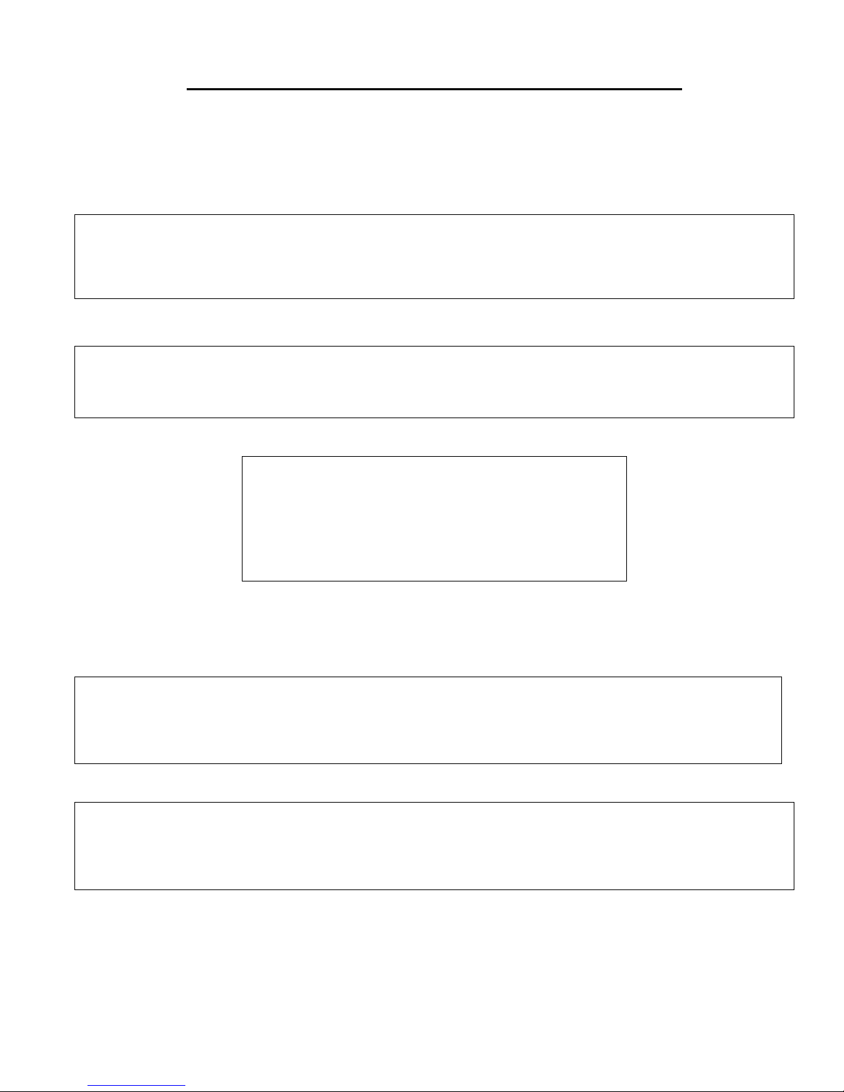
Therma-tek TF25 Operating instructions

TF75 - 75lb Fryer
TF50 - 50lb Fryer
TF40 - 40lb Fryer (shown)
TF2525 - 50lb Split Fryer
TF25 - 25lb Fryer
LISTED
U
Made in U.S.A
C US
LU
L
FRYER
OWNERS MANUAL AND INSTALLATION INSTRUCTIONS
INTRODUCTION/ SAFETY PRECAUTIONS
Thank you for choosing your new THERMA-TEK Equipment. Our Products are designed to be safe and
reliable when properly cared for and used reasonably. Your service agency or dealer recommends periodic
inspections. Installation, maintenance, and repairs should be performed by your local authorized service
agency. This equipment is not intended for home use.
This equipment is for commercial use by trained professionals familiar with commercial cooking
equipment. It is the responsibility of the Supervisor or equivalent person to ensure that users wear
suitable protective clothing and safety gear. Caution: some of the parts of the equipment become very hot
and will cause burns if accidentally touched.
FOR YOUR SAFETY
DO NOT STORE OR USE GASOLINE OR OTHER FLAMMABLE VAPORS OR LIQUIDS IN THE
VICINITY OF THIS OR ANY OTHER APPLIANCE.
FOR YOUR SAFETY
If you smell gas:
1.Shut off gas to appliance.
2. Extinguish any open flame.
3. If odor continues, immediately call your gas
supplier.
Consult your local gas supplier for instructions to be followed in the event you smell gas.
Post these instructions in a prominent location.
WARNING:IMPROPER INTALLATION, ADJUSTMENT ALTERATION, SERVICE OR
MAINTENACE CAN CAUSE PROPERTY DAMAGE, INJURY OR DEATH. READ THE
OWNERS/INTALLERS MANUAL THOUROUGHLY BEFORE INSTALLING OR SERVICING
THIS EQUIPMENT.
CALIFORNIA PROPOSITON 65 – WARNING
The burning of gas cooking fuel generates some by products, which are on the list of substances, which are known by the State
of California to cause cancer or reproductive harm. California law requires businesses to warn customers of potential exposure
to such substances. To minimize exposure to these substances, always operate this unit according to the owners/installers
manual, ensuring you provide good ventilation when cooking with gas.
PLEASE RETAIN THESE INSTRUCTIONS FOR FUTURE REFERENCE
1

INSTALLATION AND SAFETY GUIDELINES
IMPORTANT
Safe and satisfactory operation of your equipment depends on its proper installation. Installation must
conform to local codes, or in the absence of local codes. With the National Fuel Code ANSI Z223.1 (latest
addition).
All THERMA-TEK appliances are shipped with a gas pressure regulator packed with the unit. All units are
adjusted, tested, and inspected at the factory prior to shipment.
After uncrating, immediately check the equipment for visible signs of shipping damage. If such damage has
occurred, do not refuse shipment, but contact the shipper and file appropriate freight claims.
GENERAL
•Installation of this equipment should be made by licensed and authorized personnel.
•A manual gas shut-off valve must be installed in the gas supply (service) line ahead of the appliance
and gas pressure regulator installed in the gas stream for safety and ease of future service.
•The gas pressure regulator is built into the gas control.
•The appliance and its individual shut off vale must be disconnected from the gas supply system
during any pressure testing of that system in excess of ½PSI.
•The appliance must be isolated from the gas supply system by closing it individual shut off valve
during any pressure testing of the gas supply piping system at test pressures equal to or less than ½
PSI.
•Please contact the factory, the factory representative, or a local authorized service company to
perform maintenance and repairs.
RATING PLATE
Information on this plate includes the model and serial number. When communicating with the factory
about a unit or requesting special parts or information, this information is required for proper identification.
Other information on the plate is the BTU/hr input of the burners, gas pressure in inches WC, and whether
the unit is orificed for natural or propane gas.
IMPORTANT: The appliance must be connected only to the type of gas identified on the rating plate.
GAS CONVERSION
We recommend that the appliance be ordered from the factory for the type of gas at the installation site.
When gas conversion is necessary contact the factory for a proper gas conversion kit.
2

INSTALLATION AND SAFETY GUIDELINES
CLEARANCES
•The unit must be kept clear of all combustibles.
•The units must be installed with the 6” legs or casters supplied for proper operation.
•Minimum clearance from combustible construction:
Side Back
6” 6”
•Minimum clearance from non-combustible construction: 0” Side, 0” Back
LEVELING
A carpenter’s spirit level should be placed on the cooking surface and the unit leveled side-to-side, and front
to back. If it is not level, burner combustion may be erratic or the unit may not function efficiently.
AIR SUPPLY AND VENTILATION
The area around the appliance must be kept clear to avoid any obstructions of the flow of combustion and
ventilation air as well as for ease of maintenance, service, and proper appliance operation. Keep clearance
for openings into the combustion chamber and adequate air supply. Means must be provided for any
commercial, heavy duty-cooking appliance to exhaust combustion wastes to the outside of the building.
Air movement should be checked during installation. Strong exhaust fans in the hood or in the
overall air conditioning system can produce a slight draft in the room, which can interfere with pilot or
burner performance. If pilot or burner problem persists, make up air openings or baffles may have to be
provided in the room.
Filters and drip troughs should be part of any industrial hood, but consult local codes before
constructing and installing any hood. The duct system, the exhaust hood, and the filter bank must be
cleaned on a regular basis and kept free of grease.
ALTITUDE
The appliance input rating (BTU/hr) is for elevations up to 2,000 feet. For elevations above 2000 feet, the
rate should be reduced 4% for each 1000 feet above sea level. The correct orifices are installed at the
factory if the operating altitude is known at the time of sale.
WARNING
Safety labels are a required component of this unit, if missing, or not legible, they must be replaced. Inspect
periodically and replace if necessary.
AUTOMATIC SAFETY FEATURES
Pilot Safety: if the pilot would go out, gas to the main burner is interrupted.
High oil temperature detection to shut off gas to main burners should the controlling thermostat fail.
CAUTION
Local building codes will usually not permit a deep fat fryer with its open hot oil to be installed beside an
open flame of any type whether a broiler or an open top burner. Check local codes before beginning
installation.
3

INSTALLATION AND SAFETY GUIDELINES
GAS CONNECTION
The gas supply (service) line must be at least the same size or larger than the inlet line of the appliance.
THERMA-TEK Fryers are supplied with a 1/2” NPT Schedule 40 inlet. Sealant on all pipe joints must be
resistive to LP gas.
MANUAL SHUT-OFF VALVE
A manual shutoff valve must be installed in the gas service line ahead of the appliance and regulator in the
gas stream and in a position where it can be reached quickly in the event of and emergency. The manual
shut off valve is supplied by the installer.
PRESSURE REGULATOR
All commercial cooking equipment must have a pressure regulator on the incoming service line for safe and
efficient operation, since pressure may fluctuate on local demand. The regulator is built into the fryer
control. The regulators are adjusted at the factory, 4.0” WC for natural gas, and 10.0” WC for propane gas.
Ensure the supply pressure is within the following range: Natural Gas 6.0” WC to 13.0” WC / Propane Gas
11.0”WC to 13.0” WC.
Any adjustments to the regulators must be made only by qualified service personnel with proper test
equipment.
RIGID CONNECTIONS
Double check any installer supplied gas pipes visually and blow them out with compressed air to clear any
dirt particles, threading chips, or any other foreign matter before installing a service line. Those particles
will clog orifices when gas pressure is applied. All connections must be sealed with a joint compound for
LP gas, and all connections must be tested with a soapy water solution before lighting any pilots.
FLEXIBLE COUPLINGS, CONNECTORS AND CASTERS
If the unit is to be installed with flexible coupling and or quick disconnect fittings, the installer must use a
heavy duty commercial flexible connector at least ¾” NPT (with suitable strain relief) in compliance with
the standard for connectors for movable gas appliances, ANSI Z21.69-1987 and Addenda Z2.169a-1989 (or
latest edition) or connectors for movable appliances, CAN/CGA-6.16 (or latest edition) and quick
disconnect device must comply with the standard for quick disconnect devices for use with gas fuel,
ANSI Z21.41-1989 (or latest edition) or quick disconnect devices for use with gas fuel, CAN1-69 (or latest
edition). Adequate means must be provided to limit the movement of the appliance. Domestic connectors
are not suitable.
When the appliance is supplied with casters and is connected to the supply piping by means of a connector
for movable appliances, and if disconnecting the restraint is necessary, this restraint must be reconnected
after the appliance is returned to its original installation position. The strain relief is a cable attached to the
rear of the appliance.
4

INITIAL START-UP
All THERMA-TEK appliances are adjusted and tested before leaving the factory. Adjustments and
calibrations may be necessary upon installation to meet local conditions, low gas characteristics, problems
caused by rough handling or vibration during shipping, and are to be performed only by qualified service
personnel. These adjustments are the responsibility of the customers and or dealer and are not covered by
our warranty.
Check all gas connections for leaks with a soapy water solution before lighting pilots. Do Not use an open
flame to check for leaks. Putting an open flame beside a new gas connection is extremely dangerous.
Before lighting any pilots, make sure that burner valves and thermostats are in the off position.
LIGHTING/RELIGHTING THE PILOTS
CAUTION: When lighting the pilots and checking for leaks, do not stand with you face close to the
Combustion chamber.
•Turn OFF the manual shut-off valve on the incoming service line.
•Turn the operating thermostat OFF.
•Depress the pilot gas cock dial on the combination control and turn OFF.
•Wait for any accumulated gas do disperse.
•Fill the fryer vessel with liquid oil (or at least water for testing) to above the heat transfer tubes.
oWARNING: If main burners are operated with the fryer vessel empty, the fryer vessel will
be damaged.
•Open the manual shut-off valve on the incoming service line.
•Apply a lit match to the pilot burner head.
•Turn the gas cock dial on the combination control to PILOT, depress and hold the dial until the pilot
stays lit when the dial is released. This may take a minute or longer.
•CAUTION: If the pilot and main burner go out, the Fryer must be left completely shut down for at
least 5 minutes before lighting.
•Turn the gas cock dial to on, turn thermostat to desired setting.
SHUTDOWN
•Nightly shutdown: Turn thermostat to off position, turn gas cock dial on combination valve to
PILOT, pilots will remain lit.
•Complete shutdown: Turn thermostats to off position. Turn gas cock dial on combination valve to
OFF. Turn main gas supply to fryer off.
5
OPERATING INSTRUCTIONS
BEFORE USE
All units are wiped clean with solvents at the factory to remove any visible signs of dirt, oil or grease
remaining from the manufacturing process. They should be washed thoroughly with hot soapy water to
remove film residue and any installation dust or debris before being used for food preparation, then rinsed
and wiped dry. Also wash any accessories shipped with the unit.
HEATING THE VESSEL
This step checks the main burner operation and initial thermostat calibration.
•Fill the fryer with water to the oil level line inscribed into the back of the tank.
•Set the operating thermostat dial to 200 degrees F, just below the boiling point of water.
•The burner should shut off just as the water starts to boil.
•When satisfied that the burners and thermostat are operating properly, drain the vessel of water and
dry thoroughly. Refill it with shortening.
FINAL PREPARATION
When using liquid shortening (cooking oil), fill the fryer to the “OIL LEVEL” line inscribed on the back of
the fryer vessel.
When using solid shortening, either melt it first or cut in into small pieces and pack it below the heat tubes,
between the tubes, and on top of the tubes, leaving no air spaces around the tubes and being careful not to
disturb the sensing bulbs. Melt this shortening by turning ON the burners for five to ten seconds OFF for a
minute, etcetera, until the shortening is melted. If you see smoke coming from the oil while melting this
way, shorten the ON time cycle and lengthen the OFF cycle, as smoke shows that you are scorching the
shortening, cutting its useful life.
NEVER ATTEMP TO MELT A SOLID BLOCK OF SHORTENING BY SETTING IT ON TOP OF
THE HEAT TUBES. This is unsafe, inefficient, and will probably damage the fryer vessel.
When the fryer vessel is filled and shortening is melted, replace the crumb screen over the heat tubes.
Before starting operation, turn the thermostat to the desired cooking temperature, and wait for the
temperature to stabilize.
WARNINGS
•Do not move a fryer filled with hot oil or water.
•Do not go near the area directly over the flue outlet when the fryer is in operation.
•Always wear oil-proof, insulated gloves when working with a fryer filled with hot oil.
•Always drain hot oil into a steel container. Hot oil will melt plastic buckets and crack glass
containers.
6
DAILY OPERATION

GENERAL USE OF THE FRYER
For consistent product quality, convenience, and long term savings, use a high quality liquid frying
compound
Temperature of frying compound. Although 350’F is the usual temperature recommended for most cooking
operations, frying should be carried on at the lowest temperature, which will produce a high quality end
product while ensuring maximum life of the frying compound.
When the fryer is not in use, the operating thermostat should be set to a lower temperature than used during
cooking. Light loads may also be cooked at lower temperatures. A good operator will experiment to
determine the best temperature and load conditions for the various foods to be cooked.
Salting; Operators sometimes salt the food over the frying vessel. This practice should be avoided, as salt
deteriorates the frying compound quickly and flavors everything being cooked, not just the batch being
salted.
FILTERING
The frying compound should be filtered at least daily, or even more frequently if cooking is heavy. This
assures the longest life possible for the frying compound, gives better taste to the products being prepared,
and minimizes flavors being transferred from batch to batch.
WHEN FILTERING, NEVER LEAVE THE FILTER UNATTENDED!
The action of the oil moving through the hose lines could jog a flexible return hose out of the filter pan,
spraying hot oil and cause severe burns.
If using solid shortening, always make sure the return is clear before turning OFF the filter motor, and hang
any flexible lines up to drain. Solid shortening will solidify as it cools and clog the lines.
CLOSING
When closing at night, filter the oil in all fryers and drain the filter lines. Cover the open tanks of oil. Turn
the thermostat to the OFF position. Turn the gas cock dial on the combination control to OFF.
SHUTTING DOWN
When shutting down for longer than overnight, drain the frying compound, clean the vessel thoroughly,
either discard the frying compound or return it filtered to the vessel and then cover it.
Set the thermostat to the OFF position. Turn the gas cock dial on the combination control to OFF.
Turn the manual shut off valve on the incoming service line to OFF position
7
CARE AND CLEANING

Any piece of equipment works better and lasts longer when properly maintained. Cooking equipment is no
exception. Your THERMA-TEK appliance must be kept clean during the workday and thoroughly cleaned
at the end of the day.
DAILY
•Remove and wash all removable parts.
•Clean all exterior surfaces of the body. Do not use cleansers, steel wool, or any other abrasive
material on the stainless steel.
•Filter the cooking oil and replace if necessary. The oil should be filtered more often than daily under
heavy use.
WEEKLY
•Completely drain the fryer vessel into either the filter or steel container. Do not use a plastic bucket
or glass container.
•Clean the vessel with a good grade of cleaner or hot water and a strong detergent.
•Close the drain valve and refill with either cleaning solution or water and detergent.
•Bring to a rolling boil, turn the heat down, and let the mixture stand until deposits and/or carbon
spots can be rubbed of with a Teflon brush.
•Scrub the vessel walls and heat transfer tubes, then drain the vessel and rinse in clear water.
PERIODIC
The fryer should be checked and adjusted periodically by qualified service personnel as part of a regular
kitchen maintenance program. This service should include the removal of any built-up grease in the control
area.
CAUTION: Do not let water splash into a tank of hot oil, it will splatter and can cause severe burns.
STAINLESS STEEL
•All stainless steel body parts should be wiped regularly with hot soapy water during the day and with
a liquid cleaner designed for this material at the end of each day. Do not use steel wool, abrasive
cloths, cleansers or powders to clean stainless steel surfaces. If it is necessary to scrape stainless
steel to remove encrusted materials, soak in hot water to loosen the material, then use a nylon or
wood scraper to loosen debris. Never use a spatula, knife or any other metal tool to scrape stainless
steel. These tools will scratch the stainless steel.
8
TROUBLESHOOTING
These troubleshooting procedures must be carried out only by a Factory Authorized Maintenance & Repair Center for Warranty
Repair. The problems and possible solutions given below cover those most commonly encountered.

PILOT BURNER MALFUNCTION
Pilot will not ignite; no evidence of gas at the pilot burner.
•Check that the gas valve is open and gas is present at the valve.
•Check pilot burner adjustment. Adjust the pilot flame to extend above the top of the pilot. Pilot adjust screw is located
beneath cover screw.
•Remove pilot gas supply line and check for dirt. Blow out if necessary and reinstall.
•Check pilot burner orifice for dirt.
Pilot burner ignites but will not remain lit when gas cock dial is released.
•Check that the thermopile lead is firmly into the safety valve.
•Remove end of thermopile lead from safety valve and clean with fine sandpaper.
•If thermopile is defective replace it.
•Check connection of the lead from safety valve to hi-limit, if defective replace it.
•Pilot flame may be too high or too low. Adjust flame by turning pilot flow adjustment screw.
•Check the hi-limit wire connection between the safety valve and the thermopile.
•Check hi-limit safety switch, if defective replace it.
Pilot flame of proper size but unstable. Flame wavers and does not envelope the thermopile.
•Check for drafts, which might be caused by air conditioning equipment or make-up air apparatus. Turn these OFF and
recheck the pilot.
MAIN BURNER MALFUNCTIONS
Main burner will not come ON; no gas present at main burner.
•Check that the gas valve is open.
•Check that pilot is ignited and is operating properly.
•The combination control may be defective. Replace it if necessary.
Main burner appears small and lazy; fryer is not heating up quickly.
•Check gas pressure at the pressure tap on the manifold pipe located behind the door panel. Use a standard water type U-
gauge manometer. With the burners in operation, the manifold pressure should be 4” WC natural gas and 10” WC on
propane gas. If not, unscrew the cover of the pressure regulator. Use a screwdriver to turn adjusting screw clockwise to
increase gas pressure to burner, counterclockwise to decrease pressure to the burner. Replace cover and plug.
Signs of excessive temperature; frying compound scorches and quickly becomes discolored.
•Check operating thermostat. May be out of calibration; recalibrate.
•Check gas pressure as outlined above.
•Cooking compound of inferior quality or used too long; replace.
Fryer will not reach temperature setting and/or runs erratic.
•Incorrect location of sensor probe or defective sensor.
•Operating thermostat defective. Replace it if necessary.
Fryer temperature cannot be controlled; runs to hi-limit temperature.
•Operating thermostat defective.
9
HOW TO OBTAIN SERVICE
For warranty service, contact your local THERMA-TEK authorized service agency. Provide him with the
Model #, Serial #, date of installation, and a brief description of the problem. If you need assistance

locating the authorized service agency in your area, contact your local dealer. He will have a listing of
authorized dealers in your area, or on the web www.therma-tek.com
We want you to remain a satisfied customer. If a problem comes up that cannot be resolved to your
satisfaction, please contact our customer service at:
714-968-7498
714-968-3529 (fax)
877-THERTEK (toll free)
For technical support call: 570-455-3000
866-826-8993
10
WARRANTY

THERMA-TEK FOR INSTALLATION IN THE U.S.A TERMS OF SALE AND
ORIGINAL EQUIPMENT WARRANTY.
ORIGINAL EQUIPMENT WARRANTY (effective June 1, 2005)
The Therma-Tek Corporation warrants its new product(s) to be free from defects in material and workmanship for a period of one (1) year from the date of
original installation, not to exceed eighteen (18) months from shipment from the factory provided proof of installation date is supplied to Therma-Tek prior to
work being performed.
This warranty shall be subject to the following conditions.
1. This warranty is limited to product(s) sold to the original commercial user.
2. The liability of Therma-Tek under this warranty is limited to, at Therma-Tek’s option, the replacement or repair of any part found by Therma-Tek
to be not as warranted herein, provided that written notice of defects shall have been supplied to Therma-Tek within thirty (30) days after its occurrence.
3. Therma-Tek shall bear the normal labor charges incurred in such repair or replacement to the extent that such is performed within fifty (50) miles from an
office of an authorized agency of Therma-Tek, except that such obligation to bear labor charges shall not apply to products or parts installed outside the
continental United States.
4. Therma-Tek shall have no obligation as to any products(s) which have been misapplied, (including installation for residential use), mishandled , damaged,
abused, subjected to harsh chemical action or poor water quality, modified by unauthorized service personnel, damaged by flood, fire or other acts of God or
which have the serial number removed or altered.
5. Adjustments such as calibrations, initial check, air shutter adjustment, leveling, tightening of fasteners or utility connections normally associated with
original installation, are the responsibility of the dealer or installer and not that of Therma-Tek.
6. These warranty periods rather than the one (1) year period herein provided for other parts shall apply for the product(s) listed.
a. Porcelain Enamel and Paint - 90days from installation.
b. Rubber seals, light bulbs and gaskets - 90 days from installation.
c. Cast-iron parts - 120 days.
7. This states the exclusive remedy against Therma-Tek relating to the product(s) whether in contract or in tort or under any other legal theory and whether
arising out of warranties, representations, instructions, installations or defects from any cause.
8. This warranty and the liabilities set forth herein are exclusive and in lieu of all of their liabilities and warranties, expressed or implied, including but not
limited to, implied warranties or merchantability and fitness for particular purpose and constitutes the only warranty of Therma-Tek with respect to the
product(s).
9. Therma-Tek shall not be liable whether in contract or in tort, or under any other legal theory, for loss of use, revenue or profit, or for substitute use of
performance, for incidental, indirect, or special or consequential damages or for any other loss of cost of similar type.
TERMS AND CONDITIONS
Terms: Net 30 days subject to credit approval. All amounts past due are subject to a 1-1/2% per month service charge.
FOB: Factory
Prices: All prices are subject to change without notice. Prices do not include sales or any other local state tax.
Shipments: Shipments must be inspected promptly before receipt. No claims for damaged merchandise of missing parts or other errors will be
recognized unless written notice thereof is given to Therma-Tek within 30 days after the shipment.
Returned Returned goods are subject to a 20% re-stocking charge and the cost of reconditioning. Prior authorization by Therma-Tek
Goods: must be granted, and returned goods must be shipped freight pre-paid. Custom units built to buyer specifications may not be returned or
cancelled.
Note: Since continuing product improvement is a Therma-Tek policy, the factory reserves the right to change specifications, designs, and
materials without prior notice.
115 Rotary Drive, West Hazleton, PA 18202 (Manufacturing Facilites)
9121 Atlanta Ave. #331, Huntington Beach, CA 92646 (Executive Offices)
www.therma-tek.com Tel: (714) 968-7498 Fax: (724) 968-3529 877-THERTEK (843-783
12 Part No. 71000
This manual suits for next models
4
Table of contents
Other Therma-tek Fryer manuals


