Thermador PCG364GD User manual

THERMADOR PROFESSIONAL®RANGETOPS

THERMADOR PROFESSIONAL®Rangetops
Tables de Cuisson THERMADOR PROFESSIONALmc
Parrillas de THERMADOR PROFESSIONAL®
Table of Contents...............................................................................2
Table de Matières ............................................................................ 16
Índice de Materias ........................................................................... 31
Models | Modèles | Modelos
PCG364GD
PCG366G
PCG486GD
PCG364NL
PCG486NL

Table of Contents English | 2 |
This THERMADOR®appliance is made by
BSH Home Appliances Corporation
1901 Main Street, Suite 600
Irvine, CA 92614
Questions?
1-800-735-4328
www.thermador.com
We look forward to hearing from you!
Table of Contents
Safety Instructions . . . . . . . . . . . . . . . . . . . . . . . . . . . . . . . . . . . . . . . . . . . . . . . . . . . . . . . . . . . . . . . . . . . . . . . . . . . . .3
Installation. . . . . . . . . . . . . . . . . . . . . . . . . . . . . . . . . . . . . . . . . . . . . . . . . . . . . . . . . . . . . . . . . . . . . . . . . . . . . . . . . . . .5
Planning Information . . . . . . . . . . . . . . . . . . . . . . . . . . . . . . . . . . . . . . . . . . . . . . . . . . . . . . . . . . . . . . . . . . . . . . . . 5
STEP 1: Ventilation Requirements . . . . . . . . . . . . . . . . . . . . . . . . . . . . . . . . . . . . . . . . . . . . . . . . . . . . . . . . . . . . . .5
STEP 2: Cabinet Preparation. . . . . . . . . . . . . . . . . . . . . . . . . . . . . . . . . . . . . . . . . . . . . . . . . . . . . . . . . . . . . . . . . . .6
STEP 3: Unpacking, Moving, Placing & Anchoring the Cooktop . . . . . . . . . . . . . . . . . . . . . . . . . . . . . . . . . . . . . . . .7
STEP 4: Gas Requirements and Hookup . . . . . . . . . . . . . . . . . . . . . . . . . . . . . . . . . . . . . . . . . . . . . . . . . . . . . . . .11
STEP 5: Electrical Requirements, Connection and Grounding . . . . . . . . . . . . . . . . . . . . . . . . . . . . . . . . . . . . . . . .12
STEP 6: Backguard Installation . . . . . . . . . . . . . . . . . . . . . . . . . . . . . . . . . . . . . . . . . . . . . . . . . . . . . . . . . . . . . . . .13
STEP 7: Burner Test . . . . . . . . . . . . . . . . . . . . . . . . . . . . . . . . . . . . . . . . . . . . . . . . . . . . . . . . . . . . . . . . . . . . . . . .14
Installer Checklist. . . . . . . . . . . . . . . . . . . . . . . . . . . . . . . . . . . . . . . . . . . . . . . . . . . . . . . . . . . . . . . . . . . . . . . . . . . . .15
Customer Support, Parts & Accessories . . . . . . . . . . . . . . . . . . . . . . . . . . . . . . . . . . . . . . . . . . . . . . . . . . .back page
Safety Definitions
NOTICE: This indicates that damage to the appliance or property may occur as a result of non-compliance with this
advisory.
Note: This alerts you to important information and/or tips.
9 WARNING
This indicates that death or serious injuries may occur as
a result of non-observance of this warning.
9 CAUTION
This indicates that minor or moderate injuries may occur
as a result of non-observance of this warning.

Installation Instructions English | 3 |
Safety Instructions
IMPORTANT SAFETY INSTRUCTIONS
READ AND SAVE THESE INSTRUCTIONS
IMPORTANT: Save these Instructions for the Local Gas
Inspector’s use.
INSTALLER: Please leave these Installation Instructions
with this unit for the owner.
OWNER: Please retain these instructions for future
reference.
NOTE: This rangetop is NOT designed for installation in
manufactured (mobile) homes or for installation in
recreational park trailers.
IMPORTANT:
Local codes vary. Installer is responsible for ensuring that
the installation, gas connections, and grounding comply
with all applicable codes. Failure to follow appropriate local
codes and regulations may void the warranty.
DO NOT install this appliance outdoors.
Data Rating Plate
The data rating plate showing the model and serial
numbers of your rangetop is located on the underside of
the rangetop chassis near the front of the unit (see
Figure 14 on page 15). This information is necessary if
customer service is requested. Before installation, the
model and serial numbers should be entered in the
appropriate spaces in the “BEFORE CALLING FOR
SERVICE” section near the back of the Use and Care
Guide. After installation, accessing the information is
difficult.
Examine the appliance after unpacking it. In the event of
transport damage, do not plug it in.
Remove all tape and packaging before using the appliance.
Destroy the packaging after install. Never allow children to
play with packaging material.
WARNING
ELECTRICAL SHOCK HAZARD
Disconnect power before installing or servicing.
Before turning power ON, be sure that all
controls are in the OFF position. Failure to do so
can result in death or electrical shock.
WARNING
If the information in this manual is not followed
exactly, a fire or explosion may result causing
property damage, personal injury or death.
— Do not store or use gasoline or other flammable
vapors and liquids in the vicinity of this or any
other appliance.
— WHAT TO DO IF YOU SMELL GAS
• Do not try to light any appliance.
• Do not touch any electrical switch.
• Do not use any phone in your building.
• Immediately call your gas supplier from a
neighbor’s phone. Follow the gas supplier’s
instructions.
• If you cannot reach your gas supplier, call the fire
department.
— Installation and service must be performed by a
qualified installer, service agency or the gas
supplier.
For Massachusetts Installations:
1. Installation must be performed by a qualified or
licensed contractor, plumber or gas fitter qualified or
licensed by the state, province or region where this
appliance is being installed.
2. Shut-off valve must be a “T” handle gas cock.
3. Flexible gas connector must not be longer than 36''
(914 mm).
WARNING
Improper installation, adjustment, alteration, service or
maintenance can cause injury or property damage. Refer
to this manual. For assistance or additional information
consult a qualified installer, service agency, manufacturer
(dealer) or the gas supplier.
WARNING
State of California Proposition 65 Warnings:
This product contains chemicals known to the State of
California to cause cancer, birth defects or other
reproductive harm.
CAUTION
To eliminate risk of burns or fire caused by reaching over
heated surface units, cabinet storage located above the
surface units should be avoided.

Installation Instructions English | 4 |
IMPORTANT SAFETY INSTRUCTIONS
READ AND SAVE THESE INSTRUCTIONS
Electrical Power Supply
GROUNDING INSTRUCTIONS
This appliance must be grounded. Grounding reduces the
risk of electric shock by providing a safe pathway for
electric current in the event of a short circuit.
This appliance complies with one or more of the
following Standards:
• UL 858, The Standard for the Safety of Household
Electric Ranges
• ANSI Z21.1, The American National Standard for
Household Cooking Gas Appliances
• CAN 1-1.1-M81, Domestic Gas Ranges
• CSA C22.2 No. 61, Household Cooking Ranges
Check local building codes for the proper method of
appliance installation. Local codes vary. Installation,
electrical connections and grounding must comply with all
applicable codes. In the absence of local codes the
appliance should be installed in accordance with the
National Electric Code ANSI Z223.1 current issue and
National Gas Code ANSI/NFPA 70 – current issue. In
Canada, installation must be in accordance with the CAN
1-B149.1 and .2 – Installation Codes for Gas Burning
Appliances and/or local codes.
This appliance is equipped with an intermittent/interrupted
ignition device that cycles the two far left surface burners
on and off when in the ExtraLow®setting.
Gas Supply
All models are convertible to LP/Propane gas using an
accessory conversion kit.
IMPORTANT:
When installing against a combustible surface, a Low Back
guard is required. A THERMADORTM Low Back guard
must be purchased separately. See “STEP 6: Backguard
Installation” on page 13 for backguard and installation
information.
When using the Flush Island Trim, THERMADOR
recommends a minimum 12'' (305 mm) rear clearance to a
combustible surface (see Figure 1, Clearance
Requirements). Clearances from non-combustible
materials are not part of the ANSI Z21.1 scope and are not
certified by CSA. Clearances of less than 12'' (305 mm)
must be approved by the local codes and/or by the local
authority having jurisdiction.
Model Voltage Dedicated
Circuit Phase
36" with 6 Burners 120 VAC/60Hz 10 Amps Single
36" with Griddle 120 VAC/60Hz 15 Amps Single
36" with Grill 120 VAC/60Hz 20 Amps Single
48" with Griddle 120 VAC/60Hz 15 Amps Single
48" with Grill 120 VAC/60Hz 20 Amps Single
CAUTION
This unit is designed as a cooking appliance. Based on
safety considerations, never use it for warming or heating
a room.
Gas Type Min. water column Max. water column
Natural 6'' (14.9 mb) 14'' (34.9 mb)
Propane 11'' (27.4 mb) 14'' (34.9 mb)
CAUTION
When connecting the unit to propane gas, make certain
the propane gas tank is equipped with its own high-
pressure regulator in addition to the pressure regulator
supplied with the rangetop. The maximum gas pressure to
this appliance must not exceed 14.0'' water column
(34.9 mb) from the propane gas tank to the pressure
regulator.
WARNING
DO NOT block or obstruct the flow of
air through the ventilation openings.
The vent is located at the back of the
appliance. The vent needs to be
unobstructed and open to provide necessary airflow that is
important for proper performance.
DO NOT touch vent area while the appliance is on and for
several minutes after the appliance is off. Some parts of
the vent and surrounding areas become hot enough to
cause burns. Allow appliance sufficient time to cool before
touching or cleaning vent areas.
DO NOT position plastic or other heat-sensitive items on
or near the vent. These items could melt or ignite.

Installation Instructions English | 5 |
Installation
Planning Information
Before using your appliance, be sure to read this manual.
Pay special attention to the Important Safety Instructions
located at the beginning of the manual.
Safety Codes and Standards
It is the responsibility of the owner and the installer to
determine if additional requirements and/or standards
apply to specific installations.
STEP 1: Ventilation
Requirements
Refer to the Ventilation Planning Guide for approved
ventilation combinations.
It is strongly recommended that this appliance be installed
in conjunction with a THERMADOR vent hood. Due to the
high heat capability of this unit, particular attention should
be paid to the hood and duct work installation to assure it
meets local building codes.
Downdraft ventilation should not be used. The Ventilation
Planning Guide indicates the ventilation hood options and
blower capacity guidelines that are recommended for use
with all THERMADOR®ranges.
Due to the high heat of the rangetop burners, installing a
microwave oven with a ventilation system over the
rangetop is not recommended.
IMPORTANT:
Ventilation hoods and blowers are designed for use with
single wall ducting. However, some local building codes or
inspectors may require double wall ducting. Consult local
building codes and/or local agencies before starting to
assure that hood and duct installation will meet local
requirements.
NOTICE: Most ventilation hoods contain combustible
components which must be considered when planning the
installation.
1. Select Hood and Blower Models:
• For wall installations, the hood width must, at a
minimum, equal the width of the rangetop. Where
space permits, a hood larger in width than the
rangetop may be desirable for improved ventilation
performance.
• For island installations, the hood width should
overhang the rangetop by a minimum of 3" (76
mm) on each side.
2. Hood Placement:
• For best smoke elimination, the lower edge of the
hood should be installed 30" (762 mm) above the
rangetop cooking surface.
• Use a 36" (914 mm) minimum clearance if the
hood contains any combustible materials such as a
wood covering (see Figure 1 on page 7).
3. Consider Make-Up Air:
• Due to the high volume of ventilation air, a source
of outside replacement air is recommended. This is
particularly important for tightly sealed and
insulated homes.
• A qualified heating and ventilating contractor
should be consulted.
TOOLS NEEDED
Phillips screwdriver T-20 Torx screwdriver
Jigsaw 12'' adjustable wrench
Level Tape measure
Protective gloves Marking instrument
ITEMS NOT INCLUDED
3/4'' (19 mm) Flex Line Pipe Compound/Tape
9 WARNING
This appliance should not be installed with a ventilation
system that directs air in a downward direction toward
the range. This type of ventilation system may cause
ignition and combustion problems with the appliance
resulting in personal injury, property damage, or
unintended operation. Ventilating systems that direct the
air upwards do not have any restriction.

Installation Instructions English | 6 |
STEP 2: Cabinet Preparation
1. To ensure professional results, the cabinet and
countertop openings should be prepared by a qualified
cabinet worker.
2. The clearances shown in Figure 1 are required. The
same clearances apply to island installations, except
for the overhead cabinets, which must have a space
wide enough to accept the island hood.
3. The rangetop is designed to hang from the countertop
by its side flanges. The countertop however, must be
strong enough to support this rangetop. It may be
necessary to add a supporting cleat along each side
(see Figure 2) or a 2 x 4 corner brace (see Figure 3
and Figure 4 and Detail A). Another alternative would
be to construct a deck to set the rangetop on.
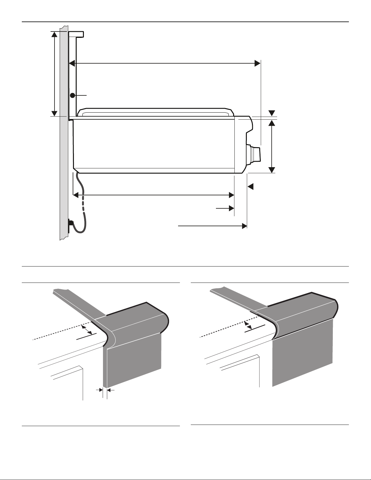
4. The rangetop can be installed in various positions with
the front either flush or projecting, depending on the
countertop’s depth. (See Figure 5, side view of
rangetop; see Figure 3, Figure 4, Figure 6 and Figure 7
for alternate mounting positions.)
5. The gas and electrical supply must be located in an
area that is accessible without requiring removal of the
rangetop. The appliance electrical power cord and gas
pipe connection are located as shown in Figure 5 and
Figure 10, respectively.
6. When installing against a combustible surface, a Low
Back guard is required. A THERMADOR Low Back
guard must be purchased separately (see “STEP 6:
Backguard Installation” on page 13).
7. When using the Flush Island Trim, THERMADOR®
recommends a minimum 12'' (305 mm) rear clearance
to a combustible surface (see Figure 1, Clearance
Requirements). Clearances from non-combustible
materials are not part of the ANSI Z21.1 scope and are
not certified by CSA. Clearances of less than 12''
(305 mm) must be approved by the local codes and/or
by the local authority having jurisdiction.
8. When the rangetop is installed against a combustible
side wall a minimum clearance of 5'' (127 mm) is
needed from the side of the rangetop to the wall.
9. The maximum depth of over head cabinets installed on
either side of the hood is 13" (330 mm). Wall cabinets
must be 18'' (457 mm) above the countertop.
10. There is a 36'' (914 mm) minimum clearance required
between the top of the cooking surface and the bottom
of an unprotected cabinet. A 30'' (762 mm) clearance
can be used when the bottom of the wood or metal
cabinet is protected by not less than 1/4'' (6 mm) of a
flame retardant material covered with not less than No.
28 MSG sheet steel, 0.015'' (0.38 mm) thick stainless
steel, 0.024'' (0.61 mm) aluminum, or 0.02'' (0.51 mm)
thick copper.
Flame retardant materials bear the mark:
UNDERWRITERS LABORATORIES INC.
CLASSIFIED MINERAL AND FIBER BOARDS
SURFACE BURNING CHARACTERISTICS
followed by the flame spread and smoke ratings. These
designations are shown as “FHC (FIame Spread/
Smoke Developed).” Materials with “O” flame spread
ratings are flame retardant. Local codes may allow
other flame spread ratings. It is the responsibility of the
installer to ensure installation is in accordance with
these ratings.
11. Establish the centerline of the rangetop’s desired
location. It should be the same as the center of the
overhead ventilation hood.
12. Cut the openings for the following installations:
• Wall installation, see Figure 3.
• Island installation, see Figure 4.
13. For installation of a 48" rangetop above two side-by-
side THERMADOR®warming drawers (WD24), refer
to Figure 8. Completing the installation as per Figure 8
will result in the left and right edges of the rangetop
being aligned with the left edge of the left-side warming
drawer and right edge of the right-side warming drawer.
If different alignment is desired, the 1⅞'' (48 mm)
horizontal distance between warming drawer cutouts
may be varied. However, maintain at least a 1⅛''
(29 mm) distance to avoid interference between the
warming drawers. Attach a 90-degree elbow to the gas
rangetop inlet pipe. All above-the-countertop
clearances must be maintained, as shown in Figure 1.
NOTES:
• If a solid side cabinet wall exists on one or both sides,
you will need to notch the front corner of the cabinet to
match the countertop notch and to allow clearance for
the rangetop front (see Detail A, Figure 3 and
Figure 4).
• If a supporting deck is used, the sides or bottom of the
cutout may be solid combustible or non-combustible
material. If the bottom is solid, provide a 12" by 12"
(305 x 305 mm) cutout in the left rear corner of the
supporting deck. This will provide clearance for the gas
inlet and power cord.
• Always keep appliance area clean and free from
combustible materials, gasoline and other flammable
vapors and liquids.
• Do not obstruct the flow of combustion and ventilation
air to the unit.

Installation Instructions English | 7 |
Installation Clearances
Figure 1: Clearance Requirements
5
" (127 mm) min.
to combustible
sidewalls
5
" (127 mm) min.
to combustible
sidewalls
5
" (127 mm) min.
to combustible
sidewalls
30" (762 mm) min.
from bottom of overhead
hood to cooking surface.
36" (914 mm) min. if
hood contains
combustible material
30"(762 mm) min.
from bottom of overhead
hood to cooking surface.
36"(914 mm) min. if
hood contains
combustible material
30" (762 mm) min.
from bottom of overhead
hood to cooking surface.
36" (914 mm) min. if
hood contains
combustible material
13" max.
cabinet
depth
13"max.
cabinet
depth
13" max.
cabinet
depth
as defined in the “National Fuel Gas Code” (ANSI Z223.1, Current Edition).
Clearances from non-combustible materials are not part of the ANSI Z21.1
scope and are not certified by CSA. Clearances of less than 12" (305 mm)
must be approved by the local codes and/or by the local authority having
jurisdiction.
30", 36", or 48"
(762, 914, or 1219 mm)
30", 36", or 48"
(762, 914, or 1219 mm)
30", 36", or 48"
(762, 914, or 1219 mm)
18
" (457 mm)
minimum
18
" (457 mm)
minimum
18
" (457 mm)
minimum
0" Sides
0"Sides
0" Sides
0" Bottom
0" Bottom
0" Bottom
Horizontal minimum distance
to combustible surface:
0" with Backguard
12" (305 mm) with Flush Island Trim
Horizontal minimum distance
to combustible surface:
0" with Backguard
12"(305 mm) with Flush Island Trim
Horizontal minimum distance
to combustible surface:
0" with Backguard
12" (305 mm) with Flush Island Trim
Shaded area above
countertop indicates min.
clearance to combustible
surfaces, combustible
materials cannot be located
within this area with Flush Island Trim.
Shaded area above
countertop indicates min.
clearance to combustible
surfaces, combustible
materials cannot be located
within this area with Flush Island Trim.
Shaded area above
countertop indicates min.
clearance to combustible
surfaces, combustible
materials cannot be located
within this area with Flush Island Trim.
See the Ventilation Planning Guide
for recommended hood options.
See the Ventilation Planning Guide
for recommended hood options.
See the Ventilation Planning Guide
for recommended hood options.
mCAUTION!
36" (914 mm) min.
to combustible
material
from Cooking
Surface
CAUTION!
36" (914 mm) min.
to combustible
material
from Cooking
Surface
CAUTION!
36" (914 mm) min.
to combustible
material
from Cooking
Surface

Installation Instructions English | 8 |
Figure 2: Installing Side Supports (both sides)
Figure 3: Wall Installation (With Countertop Backsplash)
Counter
sunk
screws
See Detail A
BD
23
5
/
16"
(59 mm)
Figure 4: Island Installation (No Countertop Backsplash)
Detail A: Front Face of Cabinet
See Detail A
2213
/
16
"
(580 mm)
22
13
/
16
"
(580 mm)
22
13
/
16
"
(580 mm)
¾" (19 mm)
minimum
D
C
B
2 x 4 Corner
Support
7
711
11
11
/
/16
16
16
"
"
(195 mm)
(195 mm)
(195 mm)
Corner Notch Detail
Corner Notch Detail
Corner Notch Detail
30'' RANGETOP 36'' RANGETOP 48'' RANGETOP
A29 ⅞'' (759 mm) 35 ⅞'' (911 mm) 47 ⅞'' (1216 mm)
B3/8'' (10 mm) 3/8'' (10 mm) 13/16'' (21 mm)
C
0'' (0 mm) Control panel projecting 1¼'' (32 mm) from base cabinet face;
11/16'' (18 mm) Notch required for standard 24''– deep base cabinet;
Control panel projecting 9/16” (14 mm) from base cabinet face;
1¼'' (32 mm) Control panel flush to cabinet face - min. 249/16'' (624 mm) - deep base cabinet required.
D29⅛'' (740 mm) 35⅛'' (892 mm) 46¼'' (1175 mm)

Installation Instructions English | 9 |
Figure 5: Side View of Rangetop
1¼"
(32 mm)
Cabinet face for installation with
projecting control panel.
Cabinet face for installation
with flush control panel.
Side flange
* Low Back shown (purchased separately)
75/8"
(194 mm)
75/8"
(194 mm)
75/8"
(194 mm)
253/8"(645 mm)
253/8"(645 mm)
253/8"(645 mm)
23
23
23
5
5
/
/16
16
16
"
"(592 mm)
(592 mm)
(592 mm)
12"
(305 mm)
12"
(305 mm)
12"
(305 mm)
½" (12.7 mm)
½" (12.7 mm)
½" (12.7 mm)
* Low Back required when there is less than 12'' (305 mm) horizontal clearance from back of rangetop to
combustible material. With more than 12'' (305 mm) of clearance, the Flush Island Trim may be used.
Figure 6: Projecting from Cabinet Front
Front projects outward 9/16" (14 mm) as
shown from standard 24"-deep base.
Notch Depth
11/16"(18 mm)
9/16
"(14 mm)
Figure 7: Flush to Cabinet Front
1¼" (32 mm)
Notch Depth
Front flush with cabinets; minimum of 24
(624 mm) cabinet depth required.
9/16"

Installation Instructions English | 10 |
Figure 8: Installation of 48'' rangetop above two side-by-side
THERMADOR warming drawers - Model No. WD24
Figure 9: Installation of 48'' rangetop above two side-by-side
THERMADOR warming drawers - Model No. WD24
22
46¼"
(1,175 mm)
22½"
(572 mm)
7
WD24
Cutout WD24
Cutout
13/16"
(21 mm)
2¾" (70 mm) Vertical Distance
Between Cutouts
(See Side View for Wood Support)
1⅞" (48 mm)
Horizontal Distance
Between Cutouts
Minimum 3/4" (19 mm)
0" to 1¼"
(0 - 32 mm)
See Fig. 4
and Table
Dimension
C
9"
(229 mm)
(195 mm)
13
/
16
"
(580 mm)
11
/
16
"
Plywood support
Install additional
wood support along
front edge of cutout
2¾" (70 mm
minimum
between
cutouts
7
11
/
16”
(195 mm)
REAR
Figure 10: Bottom of Unit
¾" (19 mm) flex line
½" (12.7 mm) NPT
½" (12.7 mm) NPT
½" (12.7 mm) NPT
A manual valve must be installed external
to the appliance, in an accessible location
A manual valve must be installed external
to the appliance, in an accessible location
A manual valve must be installed external
to the appliance, in an accessible location
from the front, for the purpose of shutting
off the gas supply.
from the front, for the purpose of shutting
off the gas supply.
from the front, for the purpose of shutting
off the gas supply.
From left side to
centerline of gas inlet
5⅝" (143 mm)
From rear to centerline
of gas inlet
8½" (215 mm)
GAS INLET LOCATION

Installation Instructions English | 11 |
STEP 3: Unpacking, Moving, &
Anchoring the Rangetop
1. Verify that the appliance is correct for the type of gas
being provided. Refer to Step 4 before proceeding with
the installation.
2. Remove the outer carton and packing material from the
shipping base. Ensure that you have all rangetop
components before proceeding.
3. Remove the cooking grates, griddle plate (if
applicable), and burner caps to reduce rangetop’s
weight.
4. Leave protective film over brushed-metal surfaces, to
protect finish from scratches, until the rangetop is
installed in its final position.
5. Using a Phillips head screwdriver, remove the three
mounting brackets securing the rangetop to the pallet.
Discard the screws and brackets after removal.
6. Attach the backguard before sliding the appliance into
the final installed position (see Step 6).
7. Lift and place the rangetop in the countertop opening.
Be careful not to pinch the power cord or gas inlet.
Care should be used not to scratch the countertop.
8. Make sure that the power cord is free and hanging
loose.
9. The rangetop must be level for proper performance.
10. Replace the cooking grates, griddle plate, and burner
caps. Ensure that the burner caps are correctly seated
on the burner bases.
Assembling the Grill (not all models)
Refer to “Using the Electric Grill” in the Use and Care
Guide.
Griddle Tilt Adjustment (not all models)
Refer to “Using the Electric Griddle” in the Use and Care
Guide.
STEP 4: Gas Requirements
and Hookup
Rangetops are shipped by the factory to operate on natural
gas.They must be converted for use with propane. Verify
the type of gas being used at the installation site matches
the type of gas used by the appliance.
If the location site requires conversion from natural gas to
propane (LP), contact the dealer where the unit was
purchased or contact THERMADOR®to purchase a
conversion kit. The field conversion kit for the rangetops in
this series is THERMADOR Model PALPKITHC. Obey all
instructions in this kit for correct conversion of the gas
regulator and settings for the gas valves. Field conversion
must be done by qualified service personnel only.
Natural Gas Requirements:
Inlet Connection: 1/2'' NPT (min. 3/4'' dia. flex line)
Supply Pressure: 6'' min. to 14'' max. water column
(14.9 to 34.9 mb)
Manifold Pressure: 5'' water column (12.5 mb)
Propane Gas Requirements:
Inlet Connection: 1/2'' NPT (min. 3/4'' dia. flex line)
Supply Pressure: 11'' min. to 14'' max. water column
(27.4 mb to 34.9 mb)
Manifold Pressure: 10'' water column (24.9 mb)
9 CAUTION
Proper equipment and adequate manpower
must be used in moving the appliance to
avoid damage and/or personal injury. The unit
is heavy and should be handled accordingly.
9 WARNING
If a gas conversion kit is used, the kit shall be installed
by a qualified service agency in accordance with the
manufacturer’s instructions and all applicable codes and
requirements of the authority having jurisdiction. If the
information in the instructions is not followed exactly, a
fire, explosion or production of carbon monoxide may
result causing property damage, personal injury or loss
of life. The qualified service agency is responsible for the
proper installation of the kit. The installation is not proper
and complete until the operation of the converted
appliance is checked as specified in the manufacturer’s
instructions supplied with the kit.
9 CAUTION
When connecting unit to propane gas, make certain the
propane gas tank is equipped with its own high pressure
regulator in addition to the pressure regulator supplied
with the appliance. The pressure of the gas supplied to
the appliance regulator must not exceed a 14'' water
column (34.9 mb).

Installation Instructions English | 12 |
Gas Hook Up
• A manual gas shut-off valve must be installed external
to the appliance, in a location accessible from the front,
for the purpose of shutting off the gas supply. The
supply line must not interfere with the back of the unit.
Make sure the gas supply is turned off at the manual
shut-off valve before connecting the appliance.
• The installer should inform the owner of the location of
the gas shut-off valve. Make sure all users know where
and how to shut off the gas supply to the rangetop.
• The gas supply connections shall be made by a
competent technician and in accordance with local
codes or ordinances. In the absence of local codes, the
installation must conform to the National Fuel Gas
Code ANSI Z223.1/NFPA54-current issue.
• Always use pipe-sealing compound or Teflon®tape on
the pipe threads, and be careful not to apply excessive
pressure when tightening the fittings.
• All installer-supplied parts must conform to applicable
codes.
• Leak testing of the appliance shall be in accordance
with the following instructions.
• Turn on gas and check supply line connections for
leaks using a soap and water solution.
• Bubbles forming indicate a gas leak. Repair all
leaks immediately after finding them.
STEP 5: Electrical
Requirements, Connection
and Grounding
• Before installing, turn power OFF at the service panel.
Lock service panel to prevent power from being turned
ON accidentally. Always disconnect appliance from the
electric supply either by disconnecting power cord or
shutting off the breaker at the service panel before
servicing the appliance.
• Before you plug in an electrical cord, be sure all
controls are in the OFF position.
• All 120 Volt rangetop models must be plugged into a
mating 3-Prong, Grounding-Type Receptacle. The
receptacle must be connected to a properly dedicated
grounded and polarized electrical power supply rated
at 120VAC, Single Phase, 60HZ (see Figure 11).
9 CAUTION
The appliance must be isolated from the gas supply
piping system by closing its individual manual shut-off
valve during any pressure testing of the gas supply
piping system at test pressures equal to or less than 1/2
psig (3.5kPa).
The appliance and its individual shut off valve must be
disconnected from the gas supply piping system during
any pressure testing of the system at test pressures in
excess of 1/2 psig (3.5kPa.).
When checking the manifold gas pressure, the inlet
pressure to the regulator should be at least 6.0" W.C. for
natural gas or 11.0" for propane.
DO NOT attempt any adjustment of the pressure
regulator.
9 WARNING
DO NOT use a flame of any kind to check for gas leaks.
Model
Type Voltage Circuit
Rating Phase
36" with 6 Burners 120 VAC/60Hz 10 Amps Single
36" with Griddle 120 VAC/60Hz 15 Amps Single
36" with Grill 120 VAC/60Hz 20 Amps Single
48" with Griddle 120 VAC/60Hz 15 Amps Single
48" with Grill 120 VAC/60Hz 20 Amps Single
Table 1: Electrical Supply Circuit Requirements
9 WARNING
ELECTRICAL SHOCK HAZARD
To avoid the risk of electrical shock, personal
injury or death; verify electrical power is turned
off at the service panel and gas supply is turned off until
the rangetop is installed and ready to operate.
9 CAUTION
Improper grounding or reverse polarization will cause
malfunction (such as continuous sparking of the burner
igniters). This can damage the appliance and can create
a condition of shock hazard. If the dedicated circuit is not
correctly grounded and polarized, it is the responsibility
and obligation of the installer and user to have the
existing receptacle changed to a properly dedicated
grounded and polarized receptacle. This must be
accomplished in accordance with all applicable local
codes and ordinances by a qualified electrician. In the
absence of local codes and ordinances, the receptacle
replacement shall be in accordance with the National
Electric Code. (See Figure 11.)

Installation Instructions English | 13 |
• Observe all governing codes and ordinances when
grounding. In the absence of these codes or
ordinances observe National Electrical Code ANSI/
NFPA No. 70 current issue. See Figure 11 for
recommended grounding method.
• Power cord and receptacle should protrude no more
than 2'' (51 mm) from the rear wall.
• An electrical wiring diagram and schematic have been
attached to the back of the rangetop chassis for access
by a qualified service technician. DO NOT remove or
discard this important information.
•Installer - show the owner the location of the circuit
breaker. Mark it for easy reference.
Grounding Method
The rangetop is factory equipped with a power supply cord
with a three-prong grounding plug (with polarized parallel
blades).
STEP 6: Backguard
Installation
For island installations and other installations with over 12''
(305 mm) clearance, the included Flush Island Trim may be
used. A Low Back guard must be installed when there is
less than a 12" (305 mm) clearance between combustible
materials and back edge of rangetop. (See Figure 1 and
Figure 5.)
Clearances from non-combustible materials are not part of
the ANSI Z21.1 scope and are not certified by
CSA. Clearances of less than 12'' (305 mm) must be
approved by the local codes and/or by the local authority
having jurisdiction.
Attach the backguard before sliding the appliance into the
final installed position. Follow Steps A through E below:
a. Depending on model, remove the 2 or 3 stainless Torx
screws in the front face of the included Flush Island
Trim. Lift up to fully remove the Flush Island Trim (A,
Figure 12).
b. Slide the support brackets between the two rangetop
chassis back panels. Secure each bracket with 4 x 1½''
(38 mm) screws (B, Figure 12).
c. Slide backguard over the two brackets on the rear of
the rangetop. Fasten them together with 8 x 1½''
(38 mm) screws (C, Figure 12).
d. Fasten the front of the backguard to the rangetop with
2 or 3 x ½'' (12.7 mm) screws (D, Figure 12).
e. Place the backguard cap on top and secure using 2 x
½'' (12.7 mm) stainless screws (E, Figure 12).
Figure 11: Recommended Grounding Method
Rangetop 12'' Low Back Flush Island Trim
36''
48''
PA36GLBC
PA48GLBC
Included with rangetop
This product must be properly grounded.
NOTE: Plug styles may vary.
Figure 12: Low Back Attachment
c.) Slide backguard
over support brackets
& secure with 8 x
1½" (38 mm) screws
c.) Slide backguard
over support brackets
& secure with 8 x
1½" (38 mm) screws
c.) Slide backguard
over support brackets
& secure with 8 x
1½" (38 mm) screws
e.) Fasten cap
with 2 x ½"
(12.7 mm)
screws
e.) Fasten cap
with 2 x ½"
(12.7 mm)
screws
e.) Fasten cap
with 2 x ½"
(12.7 mm)
screws
d.) Secure front
with ½" (12.7 mm)
stainless screws
a.) Remove Trim
a.) Remove Trim
a.) Remove Trim
b.) Install support
brackets with 8
x 1½" (38 mm)
screws
b.) Install support
brackets with 8
x 1½" (38 mm)
screws
b.) Install support
brackets with 8
x 1½" (38 mm)
screws

Installation Instructions English | 14 |
STEP 7: Burner Test
Install any loose components, such as burner caps and
grates that may have been removed earlier. Be certain that
burner caps seat properly into the burner bases. Before
testing operation of the appliance, verify that the unit and
the gas supply have been carefully checked for leaks and
that the unit has been connected to the electrical power
supply. Turn the manual gas shut-off valve to the open
position.
Test Rangetop Burners
Test Burner Ignition. Select a rangetop burner knob.
Push in and turn counterclockwise to HI. The ignitor/spark
module will produce a clicking sound. Once the air has
been purged from the supply lines, the burner should light
within four (4) seconds.
Test Flame: High Setting. Turn burner on to HI. See
Figure 13 for appropriate flame characteristics. If any of the
rangetop burners continue to burn mostly or completely
yellow, verify that the burner cap is positioned properly on
the burner base, then re-test. If flame characteristics do not
improve, call THERMADOR service.
Test Flame: Low Setting. Turn burner on to LOW.Verify
that the flame completely surrounds the burner. There
should be a flame at each burner port and there should be
no air gap between the flame and the burner. If any burners
do not carry over, call THERMADOR service.
The two far left burners feature XLO®, causing the flame to
cycle on and off when the knob is set to the XLO range.
This is normal operation.
Repeat the Ignition and Flame Test procedures described
above for each rangetop burner.
WHEN FLAME IS PROPERLY ADJUSTED:
• There should be a flame at each burner port.
• There should be no air gap between the flame and
burner port.
Call THERMADOR service if:
1. Any of the burners do not light.
2. Any of the burners continue to burn yellow.
Yellow Flames:
Further Adjustment is
required.
Yellow Tips on Outer
Cones:
Normal for LP Gas
Soft Blue Flames:
Normal for Natural Gas
If the flame is completely or mostly yellow, verify that the
regulator is set for the correct fuel. After adjustment,
retest.
Some orange-colored streaking is normal during the
initial start-up.
Allow unit to operate 4-5 minutes and re-evaluate before
making adjustments.
Figure 13: Flame Characteristics

Installation Instructions English | 15 |
Installer Checklist
Final Check List
Gas Supply
Electrical
Installer
Operation
To Clean and Protect Exterior Surfaces
• Always wipe in the direction of the stainless steel grain.
• To condition and protect stainless steel, use the
Thermador Stainless Steel Conditioner, which can be
purchased in the Thermador eShop (www.thermador-
eshop.us).
•DO NOT allow deposits to remain for long periods of
time.
•DO NOT use ordinary steel wool or steel brushes.
Small bits of steel may adhere to the surface causing
rust.
•DO NOT allow salt solutions, disinfectants, bleaches or
cleaning compounds to remain in contact with stainless
steel for extended periods. Many of these compounds
contain chemicals which could prove harmful. Rinse
with water after exposure and wipe dry with a clean
cloth.
Troubleshooting
See Use and Care Guide for troubleshooting information.
Rangetop correctly positioned in countertop recess.
Specified clearances maintained to cabinet surfaces.
Burner caps positioned properly on burner bases.
All packaging material removed.
Flush Island Trim or Backguard attached according to
instructions.
Connection: 1/2'' NPT with a minimum 3/4'' diameter
flex line.
If converting from natural to LP gas, refer to LP
Conversion Instructions for details.
Manual gas shut off valve installed in an accessible
location (without requiring removal of appliance).
Unit tested and free of gas leaks.
For models with an electric grill, a dedicated polarized
and grounded 120VAC receptacle with 20 AMP over
current protection is required for cord connection.
Write the model number and serial numbers (see
Figure 14) in the Use and Care Guide. Leave the USE
AND CARE GUIDE and INSTALLATION
INSTRUCTIONS with the owner of the appliance.
Figure 14: Data Rating Plate
Bezels centered on burner knobs, and knobs turn
freely.
Purge air from gas system by operating one of the top
burners for several minutes.
Each burner lights satisfactorily, both individually and
with other burners operating.
Burner grates are correctly positioned.

Table de matières Français | 16 |
Cet appareil électroménager de
THERMADORmc est fait par
BSH Home Appliances Ltd.
6696 Financial Drive, Unit 3
Mississauga, ON L5N 7J6
Questions?
1-800-735-4328
www.thermador.ca
Nous attendons de vos nouvelles!
Table de matières
Instructions de sécurité ............................................................................................................................................. 17
Information importante à propos de l’installation ................................................................................................... 18
ETAPE 1 : Exigences de ventilation ...................................................................................................................... 19
ETAPE 2 : Préparation de l’emplacement ............................................................................................................. 20
ETAPE 3 : Déballage, manutention et mise en place et fixation de la table de cuisson ........................................ 25
ETAPE 4 : Exigences pour l'alimentation du gaz et raccordement ........................................................................ 26
ETAPE 5 : Exigences pour l’alimentation électrique, le branchement et la mise à la terre ................................... 27
ETAPE 6 : Installation de la plaque de protection ................................................................................................. 28
ETAPE 7 : Test de brûler ....................................................................................................................................... 29
Liste de vérification pour l’installateur ..................................................................................................................... 30
Entretien, pièces et accessoires ................................................................................................................ page verso
Définitions concernant la sécurité
NOTICE : Ceci indique que la non-conformité à cet avis de sécurité peut entraîner des dégâts à l'appareil ou à la propriété.
Note : Ceci vous avertit que d'importantes informations et/ou conseils sont fournis.
9 AVERTISSEMENT
Ceci indique que le non respect de cet avertissement peut
entraîner des blessures graves, voire la mort.
9 ATTENTION
Ceci indique que le non respect de cet avertissement peut
entraîner des blessures légères ou modérées.

Instructions d'installation Français | 17 |
Instructions de sécurité
INSTRUCTIONS IMPORTANTS DE SÉCURITE
Lire Toutes Les Instructions Avant De Procéder
IMPORTANT : conserver ces instructions pour utilisation
par l’inspecteur en électricité local.
INSTALLATEUR : laisser ces instructions avec l’appareil
pour le propriétaire
PROPRIÉTAIRE : conserver ces instructions à des fins de
références.
INSTRUCTIONS DE MISE À LA TERRE
Cet appareil doit être mis à la terre. La mise à la terre réduit
les risques de décharge électrique en fournissant au
courant électrique un fil d’échappement lors d’un court
circuit.
REMARQUE : Cette table de cuisson N’EST PAS conçue
pour les maisons mobiles ni pour les véhicules récréatifs.
NE PAS installer ce table de cuisson dehors.
Fiche signalétique
La plaque de caractéristiques indique le modèle et le
numéro de série de votre table de cuisson. Elle est placée
sur le dessous du châssis de la table de cuisson, près de
l’avant de l’appareil. Cette information est requise par le
Service à la clientèle. Avant que l'installation, le modèle et
les numéros de série devrait être entré dans les espaces à
la rubrique AVANT D’EFFECTUER UN APPEL DE
SERVICE à la fin du guide d’utilisation et d’entretien.
Lorsque l'appareil est installé, il est difficile d'accéder à
l'information.
Veuillez lire toutes les instructions avant de poursuivre.
IMPORTANT : LES RÉGLEMENTATIONS LOCALES
VARIENT. L’INSTALLATION, LES BRANCHEMENTS
ÉLECTRIQUES, LES RACCORDEMENTS AU GAZ ET LA
MISE À LA TERRE DOIVENT SATISFAIRE À TOUTES
LES RÉGLEMENTATIONS APPLICABLES.
AVERTISSEMENT
Coupez l’électricité avant d’installer
l’appareil. Avant de remettre (ON)
l’électricité, assurez-vous que toutes les
commandes sont à la position OFF.
AVERTISSEMENT
L’information fournie dans le présent manuel doit être
très rigoureusement respectée, sous peine d’incendie ou
d’explosion entraînant des dommages, des blessures ou
la mort.
Une installation, un réglage, une modification, une
réparation ou un entretien adéquat peuvent entraîner
des blessures ou des dégâts matériels. Consultez le
présent manuel. Pour de l’information supplémentaire ou
de l’assistance, consultez un installateur qualifié, un
centre de réparation, le fabricant (revendeur) ou la
compagnie distributrice de gaz.
Pour les installations au Massachusetts :
1. L’installation doit être réalisée par un entrepreneur
qualifié ou agréé, un plombier ou un installateur de
gaz qualifié ou autorisé par l’État ou la région dans
laquelle cet appareil est installé.
2. Le robinet d’arrêt de gaz doit être pourvu d’une
poignée en « T ».
3. La longueur maximum autorisée du tuyau de gaz est
de 91,4 centimètres (36").
AVERTISSEMENT
L’information fournie dans le présent manuel
doit être très rigoureusement respectée, sous
peine d’incendie ou d’explosion entraînant des
dommages, des blessures ou la mort.
• Ne stockez pas et n’utilisez pas d’essence ou autres
ou la compagnie distributrice de gaz.
• SI VOUS SENTEZ UNE ODEUR DE GAZ :
• N’allumez aucun appareil.
• Ne touchez pas aux interrupteurs électriques.
• N’utilisez pas les téléphones du bâtiment.
• Appelez immédiatement votre compagnie de
gaz de chez un voisin. Suivez les instructions de
la compagnie.
• Si vous n’arrivez pas à contacter la compagnie
de gaz, appelez les pompiers.
— L’installation et les réparations doivent être réalisées
par un installateur qualité, un centre de réparation
agréé ou la compagnie de gaz.

Instructions d'installation Français | 18 |
INSTRUCTIONS IMPORTANTS DE SÉCURITE
Lire Toutes Les Instructions Avant De Procéder
Alimentation électrique
Alimentation en gaz
Tous les modèles sont convertibles au gaz propane/LP à
l’aide du nécessaire de conversion.
IMPORTANT :
Lors d’une installation contre une surface combustible,
vous devez utiliser une étagère haute ou un dosseret bas.
Vous pouvez vous acheter séparément ces articles
THERMADORmc.
Lors de l'utilisation de la garniture d'îlot THERMADOR, il
faut un espace minimal de 12 po (305 mm) entre la partie
arrière de l'appareil et la surface combustible (voir Figure 1
à la page 22). Les espaces libres jusqu'aux surfaces non
combustibles ne sont pas précisés dans la norme ANSI
Z21.1 et ne sont pas certifiés par la CSA. Tout espace libre
de moins de 12 po (305 mm) doit être approuvé par les
normes locales ou l'autorité locale ayant compétence.
Il est fortement recommandé d’installer une hotte de
ventilation adaptée au-dessus de cet appareil (voir “ETAPE
1 : Exigences de ventilation”).
Vériez la réglementation locale applicable à la construction
pour connaître la méthode approprié d’installation de
l’appareil. À défaut de réglementation, l’appareil doit être
installé conformément aux versions actuelles du Code
national du gaz combustible no Z223.1 et du Code national
de l’électricité ANSI/NFPA70 ou aux Codes d’installation
pour les appareils à gaz CAN 1-B149.1 et .2 et au Code
électrique canadien C22.1, première partie.
À cause de la chaleur intense produite par cet appareil, il
faut porter une attention particulière à l’installation de la
hotte et des conduits an de s’assurer qu’ils répondent aux
codes de construction locaux.
Cet appareil est conforme avec une ou plusieurs des
normes suivantes :
• UL 858 – norme visant la sécurité en matière de
cuisinières électriques domestiques
• ANSI Z21.1 – norme américaine régissant les
appareils électroménagers de cuisson au gaz
• CAN 1-1.1-M81, Domestic Gas Ranges
• CAN/CSA-C22.2 No 61 – cuisinières domestiques
incombe au propriétaire et à l’installateur de déterminer
si des exigences et/ou normes additionnelles
s’appliquent pour une installation spécique.
Modèle Voltage Circuit
spécialisé Phase
36 po avec six
brûleurs 120 VAC/60Hz 10 Amps Single
36 po avec plaque
chauffante 120 VAC/60Hz 15 Amps Single
36 po avec gril 120 VAC/60Hz 20 Amps Single
48 po avec plaque
chauffante 120 VAC/60Hz 15 Amps Single
48 po avec gril 120 VAC/60Hz 20 Amps Single
Gaz Min. de colonne
d'eau.
Max. de colonne
d'eau.
Naturel 6'' (14.9 mb) 14'' (34.9 mb)
Propane 11'' (27.4 mb) 14'' (34.9 mb)
ATTENTION
Si l’appareil est alimenté au gaz propane, assurez-vous
que le réservoir de propane est équipé de son propre
détendeur en plus du détendeur fourni avec l’appareil.
La pression maximum d’arrivée du gaz dans cet appareil
ne doit pas dépasser les 34,9 millibars (14 pouces à la
colonne d’eau) à partir du détendeur du réservoir de
propane.
ATTENTION
Cet appareil est conçu pour un usage culinaire. Pour des
raisons de sécurité, ne l’utilisez jamais pour chauffer une
pièce.
ATTENTION
Afin d'éliminer les risques de brûlures ou d’incendie
provoqués par la chaleur, il est conseillé d’éviter
d’installer des armoires au-dessus des appareils.
AVERTISSEMENT
Avertissements de la Proposition 65 de l'État de la
Californie :
Ce produit contient des produits chimiques connus de
l'État de la Californie pour causer le cancer, des
anomalies congénitales ou d'autres problèmes de
reproduction.

Instructions d'installation Français | 19 |
Consignes d'Installation
Renseignements de
planification
Enlever tout le matériel d’emballage et le ruban adhésif
avant d’utiliser l’appareil. Détruire le matériel d’emballage
une fois l’appareil déballé. Ne jamais laisser les enfants
jouer avec ce matériel d’emballage.
ETAPE 1 : Exigences de
ventilation
Consultez le Guide de planification de ventilation pour
connaître les combinaisons de ventilation approuvées.
Il est fortement recommandé d’installer une hotte de
ventilation THERMADOR au-dessus de la cuisinière. Une
ventilation par aspiration descendante ne devrait pas être
utilisée.
Vous ne devriez pas utiliser un système de ventilation par
aspiration descendante. Le Guide de planification de
ventilation, indique les différentes hottes en option ainsi
que des directives relatives à la capacité recommandée
des ventilateurs à utiliser avec l’une ou l’autre des
cuisinières THERMADOR
REMARQUE : Les hottes de ventilation et les ventilateurs
sont conçus pour une seule conduite murale. Certaines
réglementations locales du secteur du bâtiment exigent
toutefois une double conduite. Consultez les normes
applicables et les autorités municipales avant de
commencer les travaux an de vous assurer que
l’installation des conduites répond aux exigences locales.
AVIS : La plupart des hottes contiennent des composantes
combustibles qui doivent être prises en considération lors
de la planification de l'installation.
1. Choix des modèles de hotte et de ventilateur :
• Pour les installations murales, la largeur de la hotte
doit être au moins égale à celle de la table de
cuisson de l’appareil. Si l’espace le permet, il est
souhaitable d’installer une hotte plus large que la
table de cuisson pour améliorer les performances
de ventilation.
• Pour les installations en îlot, la largeur de la hotte
devrait dépasser d'au moins 7,62 cm (3 po) des
deux côtés de la table de cuisson de l’appareil.
2. Emplacement de la hotte
• Pour une meilleure élimination des fumées, le bord
inférieur dela hotte doit être placé à une distance
de 91,4 cm (30 po) au dessus de la table de
cuisson. (Voir Figure 1).
• Si la hotte contient des matériaux combustibles
(ex. : recouvrement en bois), elle doit être installée
à un minimum de 40 po ou plus au-dessus de la
table de cuisson.
3. Apport d’air
• Un important volume d’air étant nécessaire pour la
ventilation, il est recommandé de prévoir un apport
d’air de l’extérieur. Cet aspect revêt une
importance particulière dans les logements bien
isolés et très étanches.
• Il est conseillé de consulter un entrepreneur en
chauffage et en climatisation.
Outils Requis
Tournevis Phillips Tournevis Torx T-20
Scie sauteuse Clé ajustable de 12 po
Niveau Ruban à mesurer
Gants de protection Instrument de marquage
Articles non Inclus
Conduit flexible de ¾ po
(19 mm)
Ruban/composé pour
tuyaux
9 AVERTISSEMENT
Vous ne devriez pas installer cet appareil avec un
système de ventilation à aspiration descendante. Ce
type de système de ventilation peut présenter des
risques d’incendie et des problèmes de combustion et
ainsi entraîner des blessures corporelles, des
dommages matériels ou un fonctionnement involontaire.
Aucune restriction ne s’applique aux systèmes de
ventilation à aspiration ascendante.
This manual suits for next models
4
Table of contents
Languages:
Other Thermador Hob manuals

Thermador
Thermador Professional Series User manual

Thermador
Thermador Professional PCG36 User manual

Thermador
Thermador Professional PCG30 User manual

Thermador
Thermador PCG30 series User manual

Thermador
Thermador PCG305W User manual

Thermador
Thermador PAALTKITGW User manual

Thermador
Thermador Professional Series User manual

Thermador
Thermador Professional Series User manual

Thermador
Thermador PCG305W User manual

Thermador
Thermador PCG305W User manual