Thermador Professional PCG30 User manual

INSTALLATION MANUAL
For THERMADOR PROFESSIONAL® Rangetops
MANUEL D'INSTALLATION
Des tables de cuisson THERMADOR PROFESSIONALmc
MANUAL DE INSTALACIÓN
Para Parrillas de THERMADOR PROFESSIONAL®
Models/
Modèles/
Modelos:
PCG30
PCG36
PCG48

Table of Contents
This THERMADOR®appliance is made by
BSH Home Appliances Corporation
1901 Main Street, Suite 600
Irvine, CA 92614
Questions?
1-800-735-4328
www.thermador.com
We look forward to hearing from you!
Safety Instructions . . . . . . . . . . . . . . . . . . . . . . . . . . . . . . . . . .. . . . . .1
Important Installation Information. . . . . . . . . . . . . . . . . . . . . .. . . . . .2
Step 1: Ventilation Requirements . . . . . . . . . . . . . . . . . . . . . . . .. . . . . .3
Step 2: Cabinet Preparation . . . . . . . . . . . . . . . . . . . . . . . . . . . .. . . . . .4
Step 3: Unpacking, Moving, Placing & Anchoring the Cooktop. .. . . . . .8
Step 4: Gas Requirements and Hookup . . . . . . . . . . . . . . . . . . .. . . . . .10
Step 5: Electrical Requirements, Connection and Grounding. . .. . . . . .12
Step 6: Backguard Installation. . . . . . . . . . . . . . . . . . . . . . . . . . .. . . . . .13
Step 7: Burner Test and Adjustment. . . . . . . . . . . . . . . . . . . . . .. . . . . .14
Installer Checklist . . . . . . . . . . . . . . . . . . . . . . . . . . . . . . . . . . .. . . . . .15
To Clean and Protect Exterior Surfaces . . . . . . . . . . . . . . . . .. . . . . .15
THERMADOR®Service, Parts & Accessories. . . . . . . . . . . . back page

English 1
Safety Instructions
Important Safety Instructions
READ AND SAVE THESE INSTRUCTIONS
APPROVED FOR ALL RESIDENTIAL APPLIANCES
FOR RESIDENTIAL USE ONLY
IMPORTANT: Save these Instructions for the Local Gas
Inspector’s use.
INSTALLER: Please leave these Installation Instructions
with this unit for the owner.
OWNER: Please retain these instructions for future
reference.
PLEASE READ ENTIRE INSTRUCTIONS BEFORE
PROCEEDING
IMPORTANT:
Local codes vary. Installer is responsible for ensuring that
the installation, gas connections, and grounding comply
with all applicable codes. Failure to follow appropriate local
codes and regulations may void the warranty.
NOTE:
This rangetop is NOT designed for installation in
manufactured (mobile) homes or for installation in
recreational park trailers.
DO NOT install this appliance outdoors.
Data Rating Plate
The data rating plate showing the model and serial
numbers of your rangetop is located on the underside of
the rangetop chassis near the front of the unit (Figure 9 on
page 9). This information is required if customer service is
requested. Before installation, the model and serial
numbers should be entered in the appropriate spaces in
the “BEFORE CALLING FOR SERVICE” section near the
back of the Use and Care Guide. After installation,
accessing the information is difficult.
WARNING:
Improper installation, adjustment, alteration, service or
maintenance can cause injury or property damage.
Refer to this manual. For assistance or additional
information consult a qualified installer, service agency,
manufacturer (dealer) or the gas supplier.
WARNING:
If the information in this manual is not followed
exactly, a fire or explosion may result causing
property damage, personal injury or death.
— Do not store or use gasoline or other flammable
vapors and liquids in the vicinity of this or any other
appliance.
— WHAT TO DO IF YOU SMELL GAS
• Do not try to light any appliance.
• Do not touch any electrical switch.
• Do not use any phone in your building.
• Immediately call your gas supplier from a
neighbor’s phone. Follow the gas supplier’s
instructions.
• If you cannot reach your gas supplier, call
the fire department.
— Installation and service must be performed by a
qualified installer, service agency or the gas supplier.
For Massachusetts Installations:
1. Installation must be performed by a qualified or
licensed contractor, plumber or gas fitter qualified or
licensed by the state, province or region where this
appliance is being installed.
2. Shut-off valve must be a “T” handle gas cock.
3. Flexible gas connector must not be longer than 36”
(914mm).
WARNING:
ELECTRICAL SHOCK HAZARD—
Disconnect power before installing or
servicing. Before turning power ON, be sure
that all controls are in the OFF position.
Failure to do so can result in death or
electrical shock.

English 2
Important Installation Information
Electrical Power Supply
30'' Model:
4 Burners - 120 VAC, 60 Hz., 1 Ph., 10 Amp circuit
36" Models:
6 Burners - 120 VAC, 60 Hz., 1 Ph., 10 Amp circuit
4 Burners with Electric Griddle - 120 VAC, 60 Hz., 1 Ph., 15
Amp circuit
48" Model:
6 Burners with Electric Griddle - 120 VAC, 60 Hz., 1 Ph., 15
Amp circuit
Gas Supply
Natural Gas
6” water column (14.9 mb) min., 14” (34.9 mb) maximum
Propane Gas
11” water column (27.4 mb) min., 14” (34.9 mb) maximum
All sealed burners are rated at 18,000 BTU/HR (*15,000
BTU/HR on LP). *All models are convertible to LP/Propane
gas using an accessory conversion kit.
IMPORTANT:
When installing against a combustible surface, a Low Back
guard is required. A THERMADOR®Low Back guard must
be purchased separately. See “Step 6: Backguard
Installation” on page 13 for backguard and installation
information.
When using the Flush Island Trim, THERMADOR
recommends a minimum 12” (305 mm) rear clearance to a
combustible surface (see Figure 1, Clearance
Requirements). Clearances from non-combustible
materials are not part of the ANSI Z21.1 scope and are not
certified by CSA. Clearances of less than 12” (305 mm)
must be approved by the local codes and/or by the local
authority having jurisdiction.
It is strongly recommended that this appliance be installed
in conjunction with a suitable overhead vent hood (see
“Step 1: Ventilation Requirements” on page 3). Due to the
high heat capability of this unit, particular attention should
be paid to the hood and duct work installation to assure it
meets local building codes.
Check local building codes for the proper method of
appliance installation. Local codes vary. Installation,
electrical connections and grounding must comply with all
applicable codes. In the absence of local codes the
appliance should be installed in accordance with the
National Electric Code ANSI Z223.1 current issue and
National Gas Code ANSI/NFPA 70 – current issue. In
Canada, installation must be in accordance with the CAN
1-B149.1 and .2 – Installation Codes for Gas Burning
Appliances and/or local codes.
This appliance is equipped with an intermittent/interrupted
ignition device that cycles the two far left surface burners
on and off when in the ExtraLow®setting.
CAUTION:
When connecting the unit to propane gas, make certain
the propane gas tank is equipped with its own high-
pressure regulator in addition to the pressure regulator
supplied with the rangetop. The maximum gas pressure
to this appliance must not exceed 14.0” water column
(34.9 mb) from the propane gas tank to the pressure
regulator.
CAUTION:
This unit is designed as a cooking appliance. Based on
safety considerations, never use it for warming or
heating a room.
CAUTION:
To eliminate risk of burns or fire caused by reaching over
heated surface units, cabinet storage located above the
surface units should be avoided.

English 3
Safety Codes and Standards
This appliance complies with one or more of the following
Standards:
• UL 858, The Standard for the Safety of Household
Electric Ranges
• UL 923, The Standard for the Safety of Microwave
Cooking Appliances
• UL 507, The Standard for the Safety of Electric Fans
• UL 1026, The Standard for the Safety of Electric
Household Cooking and Food Serving Appliances
• ANSI Z21.1, The American National Standard for
Household Cooking Gas Appliances
• CSA C22.2 No. 64, Household Cooking and Liquid-
Heating Appliances
• CSA C22.2 No. 113, Fans and Ventilators
• CSA C22.2 No. 61, Household Cooking Ranges
It is the responsibility of the owner and the installer to
determine if additional requirements and/or standards
apply to specific installations.
Remove all tape and packaging before using the
appliance. Please, recycle the packaging
material, as all THERMADOR®appliance
packaging material is recyclable. Never allow
children to play with packaging material.
Step 1: Ventilation
Requirements
It is strongly recommended that a suitable exhaust hood be
installed above the appliance. Downdraft ventilation should
not be used. The table on page 4 indicates the ventilation
hood options and blower capacity guidelines that are
recommended for use with all THERMADOR rangetops.
Due to the high heat capability of this unit, particular
attention should be paid to the hood and duct work
installation to assure it meets local building codes.
Due to the high heat of the rangetop burners, installing a
microwave oven with a ventilation system over the
rangetop is not recommended.
IMPORTANT:
Ventilation hoods and blowers are designed for use with
single wall ducting. However, some local building codes or
inspectors may require double wall ducting. Consult local
building codes and/or local agencies before starting to
assure that hood and duct installation will meet local
requirements.
NOTICE:
Most ventilation hoods contain combustible components
which must be considered when planning the installation.
1. Select Hood and Blower Models:
• For wall installations, the hood width must, at a
minimum, equal the width of the rangetop. Where
space permits, a hood larger in width than the rangetop
may be desirable for improved ventilation performance.
• For island installations, the hood width should
overhang the rangetop by a minimum of 3" (76 mm) on
each side.
2. Hood Placement:
• For best smoke elimination, the lower edge of the hood
should be installed 30" (762 mm) above the rangetop
cooking surface. Use a 36" (914 mm) minimum
clearance if the hood contains any combustible
materials such as a wood covering (see Figure 1 on
page 6).
3. Consider Make-Up Air:
• Due to the high volume of ventilation air, a source of
outside replacement air is recommended. This is
particularly important for tightly sealed and insulated
homes.
• A qualified heating and ventilating contractor should be
consulted.
Tools Needed
Phillips screwdriver T-20 Torx screwdriver
Jigsaw 12” adjustable wrench
Level Tape measure
Protective gloves Marking instrument
Items Not Included
3/4” (19 mm) Flex Line Pipe Compound/Tape

English 4
Step 2: Cabinet Preparation
1. To ensure professional results, the cabinet and
countertop openings should be prepared by a qualified
cabinet worker.
2. The clearances shown in Figure 1 are required. The
same clearances apply to island installations, except
for the overhead cabinets, which must have a space
wide enough to accept the island hood.
3. The rangetop is designed to hang from the countertop
by its side flanges. The countertop however, must be
strong enough to support this rangetop. It may be
necessary to add a supporting cleat along each side
(see Figure 2) or a 2 x 4 corner brace (see Figure 3
and Figure 4 and Detail A). Another alternative would
be to construct a deck to set the rangetop on.
4. The rangetop can be installed in various positions with
the front either flush or projecting, depending on the
countertop’s depth. (See Figure 5, side view of
rangetop; see Figure 3, Figure 4, Figure 6 and Figure 7
for alternate mounting positions.)
5. The gas and electrical supply must be located in an
area that is accessible without requiring removal of the
rangetop. The appliance electrical power cord and gas
pipe connection are located on the left rear underside
of the rangetop, as shown in Figure 5 and Figure 9.
6. When installing against a combustible surface, a Low
Back guard is required. A THERMADOR®Low Back
guard must be purchased separately (see “Step 6:
Backguard Installation” on page 13).
7. When using the Flush Island Trim, THERMADOR®
recommends a minimum 12” (305 mm) rear clearance
to a combustible surface (see Figure 1, Clearance
Requirements). Clearances from non-combustible
materials are not part of the ANSI Z21.1 scope and are
not certified by CSA. Clearances of less than 12”
(305 mm) must be approved by the local codes and/or
by the local authority having jurisdiction.
8. When the rangetop is installed against a combustible
side wall a minimum clearance of 5” (127 mm) is
needed from the side of the rangetop to the wall.
9. The maximum depth of over head cabinets installed on
either side of the hood is 13" (330 mm).
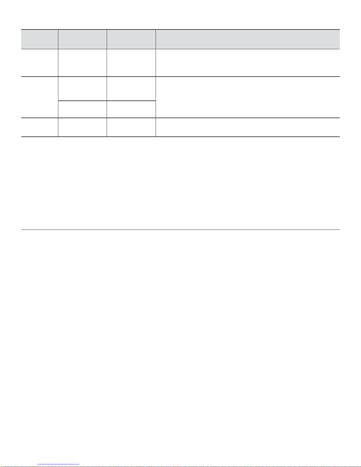
Rangetop
Width Rangetop
Configuration CFM Ventilation Options
30” 4 burners 800 (cfm) 30” or 36” Pro Wall Hood
30” or 36” Custom Insert w/ optional blower
42” Island Hood w/ optional blower
36”
4 burners with
griddle 800 (cfm) 36” or 42” Pro Wall Hood
36” Custom Insert w/ optional blower
42” or 48” Island Hood w/ optional blower
6 burners 1100 (cfm)
48” 6 burners with
griddle 1200 (cfm) 48” or 54” Pro Wall Hood**
48” Custom Insert w/ optional blower
IMPORTANT NOTES:
• It is recommended that a THERMADOR PROFESSIONAL®wall or island hood or custom insert is used with
THERMADOR PROFESSIONAL rangetops.
• Refer to www.thermador.com for a complete selection of ventilation options, blowers, and accessories.
• For high output gas rangetops (60,000 BTU or greater), the minimum of one (1) CFM of ventilation per 100 BTU is
recommended. If the rangetop has a griddle, add 200 CFM to the estimated blower capacity. Additional blower
capacity may be required for longer duct runs.
• For island applications, it is recommended to use a hood width that exceeds the width of the rangetop by 6”
(152 mm), overlapping the rangetop by 3” (76 mm) on each end.
• **Not all 48” Pro Wall Hood models can accommodate a 1300 CFM blower.
• CFM = “cubic feet per minute” (standard blower capacity rating).

English 5
10. There is a 36” (914 mm) minimum clearance required
between the top of the cooking surface and the bottom
of an unprotected cabinet. A 30” (762 mm) clearance
can be used when the bottom of the wood or metal
cabinet is protected by not less than 1/4” (6 mm) of a
flame retardant material covered with not less than No.
28 MSG sheet steel, 0.015” (0.38 mm) thick stainless
steel, 0.024” (0.61 mm) aluminum, or 0.02” (0.51 mm)
thick copper.
Flame retardant materials bear the mark:
UNDERWRITERS LABORATORIES INC.
CLASSIFIED MINERAL AND FIBER BOARDS
SURFACE BURNING CHARACTERISTICS
followed by the flame spread and smoke ratings. These
designations are shown as “FHC (FIame Spread/
Smoke Developed).” Materials with “O” flame spread
ratings are flame retardant. Local codes may allow
other flame spread ratings. It is the responsibility of the
installer to ensure installation is in accordance with
these ratings.
11. Establish the centerline of the rangetop’s desired
location. It should be the same as the center of the
overhead ventilation hood.
12. Cut the openings for the following installations:
• Wall installation, see Figure 3.
• Island installation, see Figure 4.
13. For installation of a 48" rangetop above two side-by-
side THERMADOR®warming drawers (WD24), refer
to Figure 8. Completing the installation as per Figure 8
will result in the left and right edges of the rangetop
being aligned with the left edge of the left-side warming
drawer and right edge of the right-side warming drawer.
If different alignment is desired, the 1Ǭ” (48 mm)
horizontal distance between warming drawer cutouts
may be varied. However, maintain at least a 1ǩ”
(29 mm) distance to avoid interference between the
warming drawers. Attach a 90-degree elbow to the gas
rangetop inlet pipe. All above-the-countertop
clearances must be maintained, as shown in Figure 1.
NOTES:
• If a solid side cabinet wall exists on one or both sides,
you will need to notch the front corner of the cabinet to
match the countertop notch and to allow clearance for
the rangetop front (see Detail A, Figure 3 and
Figure 4).
• If a supporting deck is used, the sides or bottom of the
cutout may be solid combustible or non-combustible
material. If the bottom is solid, provide a 12" by 12"
(305 x 305 mm) cutout in the left rear corner of the
supporting deck. This will provide clearance for the gas
inlet and power cord.
• Always keep appliance area clean and free from
combustible materials, gasoline and other flammable
vapors and liquids.
• Do not obstruct the flow of combustion and ventilation
air to the unit.
WARNING:
DO NOT block or obstruct the flow of air
through the ventilation openings. The vent
is located at the back of the appliance. The
vent needs to be unobstructed and open to
provide necessary airflow that is important
for proper performance.
DO NOT touch vent area while the
appliance is on and for several minutes
after the appliance is off. Some parts of the
vent and surrounding areas become hot
enough to cause burns. Allow appliance
sufficient time to cool before touching or
cleaning vent areas.
DO NOT position plastic or other heat-
sensitive items on or near the vent. These
items could melt or ignite.
Low Back
Vent

English 6
Figure 1: Clearance Requirements
Combustible
Materials
30” (762 mm) minimum
from bottom of overhead
hood to cooking surface.
36” (914 mm) minimum if
hood contains combustible
materials
CAUTION:
36” (914 mm)
minimum to
combustible
material from
cooking surface.
30” to 36” (762 – 914 mm) wide hood for 30” rangetop
36” to 42” (914 – 1,067 mm) wide hood for 36” rangetop
48” to 60” (1,219 – 1,524 mm) wide hood for 48” rangetop
18" (457 mm)
minimum
"A"
Horizontal minimum
distance to
combustible surface:
0” with Backguard
12” (305 mm) with
Flush Island Trim
13" (330 mm)
max cabinet
depth
Cooking surface
0" Bottom
0" Sides
VENT HOOD
as defined in the “National Fuel Gas Code” (ANSI Z223.1, Current Edition).
Clearances from non-combustible materials are not part of the ANSI Z21.1
scope and are not certified by CSA. Clearances of less than 12” (305 mm)
must be approved by the local codes and/or by the local authority having
jurisdiction.
W
A
L
L
W
A
L
L
5” (127 mm)
minimum to
combustible
sidewalls

English 7
Figure 2: Installing Side Supports (both sides)
Figure 3: Wall Installation with Countertop Backsplash
Counter
sunk
screws
See Detail A
BD
23
5
/
16”
(59 mm)
Figure 4: Island Installation (No Countertop Backsplash)
Detail A: (Front Face of Cabinet)
Vent Hood Width Requirements
Island – 42" or 48" Wide Hood for 36" Rangetop
Island – 54" or 60" Wide Hood for 48" Rangetop
See Detail A
D
22
13
/
16”
(580 mm)
¾” (19 mm)
minimum
C
B
Corner Notch Detail
2 x 4 Corner
Support
711
/16”
(195 mm)
30” Rangetop 36” Rangetop 48” Rangetop
A29 Ǭ” (76 mm) 35 Ǭ” (91 mm) 47 Ǭ” (122 mm)
B 3/8” (2 mm) 3/8” (2 mm) 13/16” (21 mm)
C
0” (0 mm) Control panel projecting 1¼” (32 mm) from base cabinet face;
11/16” (18 mm) Notch required for standard 24”– deep base cabinet;
Control panel projecting 9/16” (14 mm) from base cabinet face;
1¼” (32 mm) Control panel flush to cabinet face - min. 249/16” (624 mm) - deep base cabinet required
D29ǩ” (74 mm) 35ǩ” (89 mm) 46¼” (90 mm)

English 8
Figure 5: Side View of Rangetop
1¼”
(32 mm)
9¼” (235 mm) TO CENTERLINE
OF GAS INLET
23 5/16
”
(592 mm)
Cabinet face for installation with projecting control panel.
Cabinet face for installation with flush control panel.
253/8
”
(645 mm)
* Low Back required when there is less than
12” (305 mm) horizontal clearance from
back of cooktop to combustible material.
With more than 12” (305 mm) of clearance,
the Flush Island Trim may be used.
12”
(305 mm)
Side
flange
Low Back
(purchased separately)
75/8”
(194 mm)
½”
(12.7 mm)
Note: Unit is shown with Low Back guard (purchased separately).
Figure 6: Projecting from Cabinet Front
Front projects outward 9/16" (14 mm) as
shown from standard 24"-deep base.
Notch Depth
11
/
16
”(18 mm)
9/
16
”(14 mm)
Figure 7: Flush to Cabinet Front
1¼” (32 mm)
Notch Depth
Front flush with cabinets; minimum of 24
(624 mm) cabinet depth required.
9/16
”

English 9
Figure 8a: Installation of 48” rangetop above two side-by-
side THERMADOR warming drawers - Model No. WD24
22
46¼"
(1,175 mm)
22½"
(572 mm)
7
WD24
Cutout WD24
Cutout
13/16"
(21 mm)
2¾" (70 mm) Vertical Distance
Between Cutouts
(See Side View for Wood Support)
1⅞" (48 mm)
Horizontal Distance
Between Cutouts
Minimum 3/4" (19 mm)
0" to 1¼"
(0 - 32 mm)
See Fig. 4
and Table
Dimension
C
9"
(229 mm)
(195 mm)
13
/
16
”
(580 mm)
11
/
16
”
Figure 9: Bottom of Unit
Product Rating
Label/Serial Tag
Threading compounds must be
resistant to Propane Gas
1/2" (12.7 mm) NPT
GAS
FLOW
3/4” (19 mm) flex line
3” (76 mm)
Min.
Power
Cord
A manual valve must be installed
external to the appliance, in an acces-
sible location from the front, for the
purpose of shutting off the gas supply.
3-Prong grounding type receptacle
connected to a properly grounded and
polarized electrical supply rated at 120VAC,
10 Amps, (or 15A*) Single Phase, 60 HZ.
Figure 8b: Installation of 48” rangetop above two side-by-
side THERMADOR warming drawers - Model No. WD24
(Side View)
Plywood support
Install additional
wood support along
front edge of cutout
2¾" (70 mm)
minimum
between
cutouts
7
11
/
16”
(195 mm)
REAR
All Installer supplied parts must conform to Local Codes.
* 15 Amp 120 VAC electrical supply is required for 36" and 48" models with an electric griddle.

English 10
Step 3: Unpacking, Moving, &
Anchoring the Rangetop
• Verify that the appliance is correct for the type of gas
being provided. Refer to Step 4 before proceeding with
the installation.
• Remove the outer carton and packing material from the
shipping base. Ensure that you have all rangetop
components before proceeding.
• Remove the cooking grates, griddle plate (if
applicable), and burner caps to reduce rangetop’s
weight.
•Leave adhesive-backed foam layer over brushed-metal
surfaces, to protect finish from scratches, until the
rangetop is installed in its final position.
• Using a Phillips head screwdriver, remove the three
mounting brackets securing the rangetop to the pallet.
Discard the screws and brackets after removal.
• Attach the backguard before sliding the appliance into
the final installed position (see Step 6).
• Lift and place the rangetop in the countertop opening.
Be careful not to pinch the power cord or gas inlet.
Care should be used not to scratch the countertop.
• Make sure that the power cord is free and hanging
loose.
• The rangetop must be level for proper performance.
• Replace the cooking grates, griddle plate, and burner
caps. Ensure that the burner caps are correctly seated
on the burner bases.
Griddle Tilt Adjustment (not all models)
Check the griddle adjustment by pouring two tablespoons
of water on the back of the griddle plate (Figure 10). The
water should slowly roll into the grease tray. If not, adjust
the two screws under the back of the plate. Start with one
half turn counter-clockwise (CCW) of the screws. Further
adjustment should be made by one-quarter turn until water
slowly flows into the grease tray.
Step 4: Gas Requirements and
Hookup
Rangetops are shipped by the factory to operate on
natural gas.They must be converted for use with
propane. Verify the type of gas being used at the
installation site matches the type of gas used by the
appliance.
If the location site requires conversion from natural gas to
propane (LP), contact the dealer where the unit was
purchased or contact THERMADOR®to purchase a
conversion kit. The field conversion kit for the rangetops in
this series is THERMADOR Model PALPKITHC. Obey all
instructions in this kit for correct conversion of the gas
regulator and settings for the gas valves. Field conversion
must be done by qualified service personnel only.
CAUTION:
Proper equipment and adequate manpower
must be used in moving the appliance to
avoid damage and/or personal injury. The unit
is heavy and should be handled accordingly.
Figure 10: Griddle Plate Leveling Screws
WARNING:
If a gas conversion kit is used, the kit shall be installed
by a qualified service agency in accordance with the
manufacturer’s instructions and all applicable codes and
requirements of the authority having jurisdiction. If the
information in the instructions is not followed exactly, a
fire, explosion or production of carbon monoxide may
result causing property damage, personal injury or loss
of life. The qualified service agency is responsible for the
proper installation of the kit. The installation is not proper
and complete until the operation of the converted
appliance is checked as specified in the manufacturer’s
instructions supplied with the kit.
Move griddle
plate to the
side and turn
leveling screws

English 11
Natural Gas Requirements:
Inlet Connection: 1/2” NPT (min. 3/4” dia. flex line)
Supply Pressure: 6” min. to 14” max. water column
(14.9 to 34.9 mb)
Manifold Pressure: 5” water column (12.5 mb)
Propane Gas Requirements:
Inlet Connection: 1/2” NPT (min. 3/4” dia. flex line)
Supply Pressure: 11” min. to 14” max. water column
(27.4 mb to 34.9 mb)
Manifold Pressure: 10” water column (24.9 mb)
Hook Up
• A manual gas shut-off valve must be installed external
to the appliance, in a location accessible from the front,
for the purpose of shutting off the gas supply. The
supply line must not interfere with the back of the unit.
Make sure the gas supply is turned off at the manual
shut-off valve before connecting the appliance.
• The installer should inform the owner of the location of
the gas shut-off valve. Make sure all users know where
and how to shut off the gas supply to the rangetop.
• The gas supply connections shall be made by a
competent technician and in accordance with local
codes or ordinances. In the absence of local codes, the
installation must conform to the National Fuel Gas
Code ANSI Z223.1/NFPA54-current issue.
• Always use pipe-sealing compound or Teflon®tape on
the pipe threads, and be careful not to apply excessive
pressure when tightening the fittings.
• All installer-supplied parts must conform to applicable
codes.
• Leak testing of the appliance shall be in accordance
with the following instructions.
• Turn on gas and check supply line connections for
leaks using a soap and water solution.
• Bubbles forming indicate a gas leak. Repair all
leaks immediately after finding them.
WARNING:
Do not use a flame of any kind to check for gas leaks.
CAUTION:
When connecting unit to propane gas, make certain the
propane gas tank is equipped with its own high pressure
regulator in addition to the pressure regulator supplied
with the appliance. The pressure of the gas supplied to
the appliance regulator must not exceed a 14” water
column (34.9 mb).
CAUTION:
The appliance must be isolated from the gas supply
piping system by closing its individual manual shut-off
valve during any pressure testing of the gas supply
piping system at test pressures equal to or less than 1/2
psig (3.5kPa).
The appliance and its individual shut off valve must be
disconnected from the gas supply piping system during
any pressure testing of the system at test pressures in
excess of 1/2 psig (3.5kPa.).
When checking the manifold gas pressure, the inlet
pressure to the regulator should be at least 6.0" W.C. for
natural gas or 11.0" for propane.
Do not attempt any adjustment of the pressure regulator.

English 12
Step 5: Electrical
Requirements, Connection
and Grounding
• Before installing, turn power OFF at the service panel.
Lock service panel to prevent power from being turned
ON accidentally.
• Always disconnect appliance from the electric supply
either by disconnecting power cord or shutting off the
breaker at the service panel before servicing the
appliance.
• Before you plug in an electrical cord, be sure all
controls are in the OFF position.
• All 120 Volt rangetop models must be plugged into a
mating 3-Prong, Grounding-Type Receptacle. The
receptacle must be connected to a properly grounded
and polarized electrical power supply rated at 120VAC,
Single Phase, 60HZ. See “Electrical Power Supply
Over-current Protection Requirements” for proper over-
current protection requirements for each model.
• Observe all governing codes and ordinances when
grounding. In the absence of these codes or
ordinances observe National Electrical Code ANSI/
NFPA No. 70 current issue. See Figure 11 for
recommended grounding method.
• An electrical wiring diagram and schematic have been
attached to the back of the rangetop chassis for access
by a qualified service technician. Do not remove or
discard this important information.
Grounding Method
The rangetop is factory equipped with a power supply cord
with a three-prong grounding plug (with polarized parallel
blades).
IT MUST BE PLUGGED INTO A MATING, GROUNDING
TYPE RECEPTACLE THAT IS CONNECTED TO A
CORRECTLY POLARIZED 120 VOLT CIRCUIT (See
Figure 11).
THE THIRD, GROUND PRONG MUST NOT BE CUT OR
REMOVED UNDER ANY CIRCUMSTANCES.
Electrical Power Supply Over-current Protection
Requirements
4 Burners - 10 Amp circuit protection
6 Burners - 10 Amp circuit protection
4 Burners with electric griddle - 15 Amp circuit protection
6 Burners with electric griddle -15 Amp circuit protection
Installer - show the owner the location of the circuit
breaker. Mark it for easy reference.
WARNING:
ELECTRICAL SHOCK HAZARD
To avoid the risk of electrical shock, personal
injury or death; verify electrical power is
turned off at the service panel and gas supply
is turned off until the rangetop is installed and
ready to operate.
CAUTION:
Improper grounding or reverse polarization will cause
malfunction (such as continuous sparking of the burner
igniters). This can damage the appliance and can create
a condition of shock hazard. If the circuit is not correctly
grounded and polarized, it is the responsibility and
obligation of the installer and user to have the existing
receptacle changed to a properly grounded and
polarized receptacle. This must be accomplished in
accordance with all applicable local codes and
ordinances by a qualified electrician. In the absence of
local codes and ordinances, the receptacle replacement
shall be in accordance with the National Electric Code.
(See Figure 11.)
Figure 11: Recommended Grounding Method for 120V
Models
Receptacle
Box Cover
Plate
Three-prong
receptacle
Three-prong
plug
Note: Plug style may vary.

English 13
Step 6: Backguard Installation
For island installations and other installations with over 12”
(305 mm) clearance, the included Flush Island Trim may be
used. A Low Back guard must be installed when there is
less than a 12" (305 mm) clearance between combustible
materials and back edge of cooktop. (See Figure 1 and
Figure 5.) Clearances from non-combustible materials are
not part of the ANSI Z21.1 scope and are not certified by
CSA. Clearances of less than 12” (305 mm) must be
approved by the local codes and/or by the local authority
having jurisdiction.
Attach the backguard before sliding the appliance into the
final installed position. Follow Steps A through E below:
a. Depending on model, remove the 2 or 3 stainless Torx
screws in the front face of the included Flush Island
Trim. Lift up to fully remove the Flush Island Trim (A,
Figure 12).
b. Slide the support brackets between the two rangetop
chassis back panels. Secure each bracket with 4 x 1½”
(38 mm) screws (B, Figure 12).
c. Slide backguard over the two brackets on the rear of
the rangetop. Fasten them together with 8 x 1½”
(38 mm) screws (C, Figure 12).
d. Fasten the front of the backguard to the rangetop with
2 or 3 x ½” (12.7 mm) screws (D, Figure 12).
e. Place the backguard cap on top and secure using 2 x
½” (12.7 mm) stainless screws (E, Figure 12).
Low Back and Flush Island Trim Model Numbers
Rangetop
Size 12” Low Back
(sold separately) Flush Island Trim
30”
36”
48”
PA30GLBC
PA36GLBC
PA48GLBC
Included with rangetop
Figure 12: Low Back Attachment
b.) Install support
brackets with 8 x 1½”
(38 mm) screws
a.) Remove Flush
Island Trim
c.) Slide backguard
over support brackets
& secure with 8 x
1½” (38 mm) screws
d.) Secure front with
½” (12.7 mm)
stainless screws
e.) Fasten cap
with 2 x ½”
(12.7 mm) screws

English 14
Step 7: Burner Test and
Adjustment
Install any loose components, such as burner caps and
grates that may have been removed earlier.
Be certain that burner caps seat properly into the burner
bases. Before testing operation of the appliance, verify that
the unit and the gas supply have been carefully checked for
leaks and that the unit has been connected to the electrical
power supply. Turn the manual gas shut-off valve to the
open position.
Test Rangetop Burners
Test Burner Ignition. Select a rangetop burner knob.
Push in and turn counterclockwise to HI. The ignitor/spark
module will produce a clicking sound. Once the air has
been purged from the supply lines, the burner should light
within four (4) seconds.
Test Flame: High Setting. Turn burner on to HI. See
Figure 13 for appropriate flame characteristics. If any of the
rangetop burners continue to burn mostly or completely
yellow, verify that the burner cap is positioned properly on
the burner base, then re-test. If flame characteristics do not
improve, call THERMADOR®.
Test Flame: Low Setting. Turn burner on to LOW.Verify
that the flame completely surrounds the burner. There
should be a flame at each burner port and there should be
no air gap between the flame and the burner. If any burners
do not carry over, call THERMADOR.
The two far left burners feature XLO®, causing the flame to
cycle on and off when the knob is set to the XLO range.
This is normal operation.
Repeat the Ignition and Flame Test procedures described
above for each rangetop burner.
WHEN FLAME IS PROPERLY ADJUSTED:
• There should be a flame at each burner port.
•There should be no air gap between the flame and
burner port.
Call THERMADOR if:
1. Any of the burners do not light.
2. Any of the burners continue to burn yellow.
Figure 13: Flame Characteristics
If the flame is completely or mostly yellow, verify that the
regulator is set for the correct fuel. After adjustment,
retest.
Some orange-colored streaking is normal during the
initial start-up.
Allow unit to operate 4-5 minutes and re-evaluate before
making adjustments.
Yellow Flames:
Further adjustment is required.
Yellow Tips on Outer Cones:
Normal for LP Gas.
Soft Blue Flames:
Normal for Natural Gas.

English 15
Installer Checklist
Final Check List
FRangetop correctly positioned in countertop recess.
FSpecified clearances maintained to cabinet surfaces.
FBurner caps positioned properly on burner bases.
FAll packaging material removed.
FFlush Island Trim or Backguard attached according to
instructions.
FThe griddle plate tilted slightly forward. (See “Griddle
Tilt Adjustment (not all models)” on page 10.)
Gas Supply
FConnection: 1/2” NPT with a minimum 3/4” diameter
flex line.
FIf converting from natural to LP gas, refer to LP
Conversion Instructions for details.
FManual gas shut off valve installed in an accessible
location (without requiring removal of appliance).
FUnit tested and free of gas leaks.
Electrical
FFor models with the electric griddle, a polarized and
grounded 120VAC receptacle with 15 AMP over
current protection is provided for service cord
connection.
Operation
FBezels centered on burner knobs, and knobs turn
freely.
FPurge air from gas system by operating one of the top
burners for several minutes.
FEach burner lights satisfactorily, both individually and
with other burners operating.
FBurner grates are correctly positioned.
Installer
FWrite the model number and serial numbers (see
“Data Rating Plate” on page 1 for location) in the Use
and Care Guide. Leave the USE AND CARE GUIDE
and INSTALLATION INSTRUCTIONS with the owner
of the appliance.
To Clean and Protect Exterior Surfaces
The stainless steel surfaces may be cleaned by wiping with
a damp soapy cloth. Any mild glass cleaner will remove
fingerprints and smears.
Follow all cleaning by rinsing with clear water. Wipe dry
with a clean soft cloth to avoid water marks. For
discolorations or deposits that persist, use a non-scratching
household cleanser or stainless steel polishing powder with
a little water and a soft cloth. For stubborn cases, use a
plastic scouring pad or soft bristle brush together with
cleanser and water. Rub lightly in direction of polishing
lines or “grain” of the stainless finish. Avoid using too much
pressure which may mar the surface.
Use a stainless steel cleaner/polish to protect the finish and
maintain appearance.
DO NOT allow deposits to remain for long periods of time.
DO NOT use ordinary steel wool or steel brushes. Small
bits of steel may adhere to the surface causing rust.
DO NOT allow salt solutions, disinfectants, bleaches or
cleaning compounds to remain in contact with stainless
steel for extended periods. Many of these compounds
contain chemicals which could prove harmful. Rinse with
water after exposure and wipe dry with a clean cloth.
Specifications are for planning purposes only. Refer to
installation instructions and consult your countertop supplier
prior to making a counter opening. For the most detailed
information, refer to the installation instructions accompanying
this product or write THERMADOR®indicating the model
number.
We reserve the right to change specifications or design without
notice. Some models are certified for use in Canada.
THERMADOR is not responsible for products which are
transported from the U.S. for use in Canada. Check with your
local Canadian distributor or dealer.

Table des matières
Cet appareil électroménager de
THERMADORmc est fait par
BSH Home Appliances Corporation
1901 Main Street, Suite 600
Irvine, CA 92614
Questions?
1-800-735-4328
www.thermador.ca
Nous attendons de vos nouvelles!
Instructions de sécurite . . . . . . . . . . . . . . . . . . . . . . . . . . . . . . . . . . .1
Information importante à propos de l’installation . . . . . . . . . . . . . .2
Chapitre 1 : Exigences de ventilation . . . . . . . . . . . . . . . . . . . . . . . . . . . . . . . . . 3
Chapitre 2 : Préparation de l’emplacement . . . . . . . . . . . . . . . . . . . . . . . . . . . . . 4
Chapitre 3 : Déballage, manutention et mise en place et fixation de
la table de cuisson . . . . . . . . . . . . . . . . . . . . . . . . . . . . . . . . . . . . . . . . . . . . . . 10
Chapitre 4 : Exigences pour l'alimentation du gaz et raccordement . . . . . . . . . 10
Chapitre 5 : Exigences pour l’alimentation électrique, le branchement
et la mise à la terre . . . . . . . . . . . . . . . . . . . . . . . . . . . . . . . . . . . . . . . . . . . . . . 12
Chapitre 6 : Installation de la plaque de protection . . . . . . . . . . . . . . . . . . . . . . 13
Chapitre 7 : Test et réglage de brûler . . . . . . . . . . . . . . . . . . . . . . . . . . . . . . . . 14
Liste de vérification pour l’installateur . . . . . . . . . . . . . . . . . . . . .15
Nettoyage et protection des surfaces extérieures . . . . . . . . . . . .15
Service, pièces et accessories THERMADORmc. . . . . . . page verso

Français 1
Instructions de sécurite
Instructions importants de sécurite
LIRE TOUTES LES INSTRUCTIONS AVANT DE PROCÉDER
APPROUVÉ POUR TOUT APPAREIL RÉSIDENTIEL
POUR UTILISATION RÉSIDENTILLE SEULEMENT
IMPORTANT : conserver ces instructions pour utilisation
par l’inspecteur en électricité local.
INSTALLATEUR : laisser ces instructions avec l’appareil
pour le propriétaire
PROPRIÉTAIRE : conserver ces instructions à des fins de
références.
Remarque :
Cette table de cuisson N’EST PAS conçue pour les
maisons mobiles ni pour les véhicules récréatifs.
NE PAS installer ce table de cuisson dehors.
Fiche signalétique
La plaque de caractéristiques indique le modèle et le
numéro de série de votre table de cuisson. Elle est placée
sur le dessous du châssis de la table de cuisson, près de
l’avant de l’appareil. Cette information est requise par le
Service à la clientèle. Avant que l'installation, le modèle et
les numéros de série devrait être entré dans les espaces à
la rubrique AVANT D’EFFECTUER UN APPEL DE
SERVICE à la fin du guide d’utilisation et d’entretien.
Lorsque l'appareil est installé, il est difficile d'accéder à
l'information.
Veuillez lire toutes les instructions avant de poursuivre.
IMPORTANT : LES RÉGLEMENTATIONS LOCALES
VARIENT. L’INSTALLATION, LES BRANCHEMENTS
ÉLECTRIQUES, LES RACCORDEMENTS AU GAZ ET LA
MISE À LA TERRE DOIVENT SATISFAIRE À TOUTES
LES RÉGLEMENTATIONS APPLICABLES.
AVERTISSEMENT :
Coupez l’électricité avant d’installer
l’appareil. Avant de remettre (ON)
l’électricité, assurez-vous que toutes les
commandes sont à la position OFF.
AVERTISSEMENT :
L’information fournie dans le présent manuel doit être
très rigoureusement respectée, sous peine d’incendie ou
d’explosion entraînant des dommages, des blessures ou
la mort.
Une installation, un réglage, une modification, une
réparation ou un entretien adéquat peuvent entraîner
des blessures ou des dégâts matériels. Consultez le
présent manuel. Pour de l’information supplémentaire ou
de l’assistance, consultez un installateur qualifié, un
centre de réparation, le fabricant (revendeur) ou la
compagnie distributrice de gaz.
Pour les installations au Massachusetts :
1. L’installation doit être réalisée par un entrepreneur
qualifié ou agréé, un plombier ou un installateur de
gaz qualifié ou autorisé par l’État ou la région dans
laquelle cet appareil est installé.
2. Le robinet d’arrêt de gaz doit être pourvu d’une
poignée en « T ».
3. La longueur maximum autorisée du tuyau de gaz est
de 91,4 centimètres (36").
AVERTISSEMENT :
L’information fournie dans le présent manuel
doit être très rigoureusement respectée, sous
peine d’incendie ou d’explosion entraînant des
dommages, des blessures ou la mort.
• Ne stockez pas et n’utilisez pas d’essence ou autres
ou la compagnie distributrice de gaz.
• SI VOUS SENTEZ UNE ODEUR DE GAZ :
• N’allumez aucun appareil.
• Ne touchez pas aux interrupteurs électriques.
• N’utilisez pas les téléphones du bâtiment.
• Appelez immédiatement votre compagnie de
gaz de chez un voisin. Suivez les instructions de
la compagnie.
• Si vous n’arrivez pas à contacter la compagnie
de gaz, appelez les pompiers.
—
L’installation et les réparations doivent être réalisées
par un installateur qualié, un centre de réparation
agréé ou la compagnie de gaz.

Français 2
Information importante à propos de
l’installation
Alimentation électrique :
Modèle 76,2 cm (30 po)
Brûleurs 4 : 120 VCA, 60 Hz, monophasé, circuit de 10 A
ModèleS de 91,4 cm (36 po)
Brûleurs 6 : 120 VCA, 60 Hz, monophasé, circuit de 10 A
Brûleurs 4 avec grille électrique : 120 VAC, 60 Hz,
monophasé, circuit de 15 A
Modèle de 1,22 m (48 po)
Brûleurs 6 avec grille électrique : 120 VCA, 60 Hz,
monophasé, circuit de 15 A
Alimentation en gaz :
Gaz naturel : 14,9 mb (6 po) min. à 34,9 mb (14 po) max. à
la colonne d’eau.
Gaz propane : 27,4 mb (11 po) min. à 34,9 (14 po) max. à
la colonne d’eau).
Tous les brûleurs scellés sont cotés à 18 000 Btu/h (*15
000Btu/h pour LP). *Tous les modèles sont convertibles au
gaz propane/LP à l’aide du nécessaire de conversion.
IMPORTANT
Lors d’une installation contre une surface combustible,
vous devez utiliser une étagère haute ou un dosseret bas.
Vous pouvez vous acheter séparément ces articles
THERMADORmc.
Lors de l'utilisation de la garniture d'îlot THERMADOR, il
faut un espace minimal de 12 po (305 mm) entre la partie
arrière de l'appareil et la surface combustible (voir Figure 1
à la page 6). Les espaces libres jusqu'aux surfaces non
combustibles ne sont pas précisés dans la norme ANSI
Z21.1 et ne sont pas certifiés par la CSA. Tout espace libre
de moins de 12 po (305 mm) doit être approuvé par les
normes locales ou l'autorité locale ayant compétence.
Il est fortement recommandé d’installer une hotte de
ventilation adaptée au-dessus de cet appareil (voir
“Chapitre 1 : Exigences de ventilation”).
Vériez la réglementation locale applicable à la construction
pour connaître la méthode approprié d’installation de
l’appareil. À défaut de réglementation, l’appareil doit être
installé conformément aux versions actuelles du Code
national du gaz combustible no Z223.1 et du Code national
de l’électricité ANSI/NFPA70 ou aux Codes d’installation
pour les appareils à gaz CAN 1-B149.1 et .2 et au Code
électrique canadien C22.1, première partie.
Cet appareil est équipé d’un système d’allumage
intermittent qui allume et éteint les deux brûleurs de
gauche lorsqu’ils sont réglés sur ExtraLowmc.
À cause de la chaleur intense produite par cet appareil, il
faut porter une attention particulière à l’installation de la
hotte et des conduits an de s’assurer qu’ils répondent aux
codes de construction locaux.
MISE EN GUARDE :
Si l’appareil est alimenté au gaz propane, assurez-vous
que le réservoir de propane est équipé de son propre
détendeur en plus du détendeur fourni avec l’appareil.
La pression maximum d’arrivée du gaz dans cet appareil
ne doit pas dépasser les 34,9 millibars (14 pouces à la
colonne d’eau) à partir du détendeur du réservoir de
propane.
MISE EN GUARDE :
Cet appareil est conçu pour un usage culinaire. Pour des
raisons de sécurité, ne l’utilisez jamais pour chauffer une
pièce.
MISE EN GARDE :
Afin d'éliminer les risques de brûlures ou d’incendie
provoqués par la chaleur, il est conseillé d’éviter
d’installer des armoires au-dessus des appareils.
Other manuals for Professional PCG30
1
This manual suits for next models
2
Table of contents
Languages:
Other Thermador Hob manuals

Thermador
Thermador PCG305W User manual

Thermador
Thermador PCG364GD User manual

Thermador
Thermador PAALTKITGW User manual

Thermador
Thermador Professional Series User manual

Thermador
Thermador PCG30 series User manual

Thermador
Thermador Professional Series User manual

Thermador
Thermador Professional PCG36 User manual

Thermador
Thermador PCG304G User manual

Thermador
Thermador PCG305W User manual

Thermador
Thermador PCG305W User manual