THERMAL INTEGRATION XCEL User manual

Thermal Integration Ltd., 8 Curzon Road, Sudbury, Suffolk CO10 2XW
Te : 0845 2411441
XCEL HEAT BANKS
Installation Instructions
Rev03-09032018

2
Congratu ations on your purchase of an Xce Heat Bank therma store. The Xce is manufactured
in the UK from top qua ity materia s and meets a the atest re evant safety and constructiona
standards. The high grade aser cut and aser we ded Dup ex stain ess stee cy inder offers
exceptiona strength and corrosion resistance, backed by a ifetime guarantee. Insu ation eve s
exceed the atest requirements of Bui ding Regu ation Part L.
The Xce may be used with gas, oi or biomass boi ers, wood burners, so ar pane s, heat pumps,
e ectric heating e ements, or centra boi er systems. Two arge 1½” connections are provided for
connecting to wood burners and may be either pumped or on gravity circu ation. A arge 1m2 coi is
provided as standard for connection of so ar pane s. Three 2¼” connections are provided for
immersion heaters or retro-fit coi s. An additiona twenty two ¾” connections are provided for
pumped circuits, thermostats and sensors.
The Xcel’s DHW 160kW heat exchanger can heat mains water supplied at pressures between 0.1 and 10
bar, without the need for pressure reducing valves. Intermittent water supplies will not cause problems,
unless they are utilised for overheat protection.
The Xcel cylinder connects to a separate feed and expansion tank incorporating an open vent pipe, and
remains unpressurised without the need for safety discharge valves or annual maintenance. It is also
possible to connect the Xcel as a pressurised storage system, using the optionally supplied safety controls
in place of a feed tank, providing the Xcel is not connected to a uncontrolled heat source such as wood
burner or large solar array.
IMPORTANT Genera Requirements:
1. IN ORDER FOR GUARANTEES ON THIS SYSTEM TO START:
(a) THE INSTALLER MUST FILL IN THE FORM AT THE BACK OF THESE INSTRUCTIONS.
(b) THE OWNER OR OCCUPANT MUST FILL IN THE FORM AT THE BACK OF THESE INSTRUCTIONS AND
RETURN TO:
2. PLEASE READ THESE INSTRUCTIONS IN FULL BEFORE PROCEEDING WITH INSTALLATION.
3. THE XCEL SHOULD BE INSTALLED AND MAINTAINED BY A COMPETENT INSTALLER IN ACCORDANCE WITH G3
BUILDING REGULATION (ENGLAND AND WALES), P3 TECHNICAL STANDARD (SCOTLAND) OR P5 BUILDING
REGULATION (NORTHERN IRELAND), AS WELL AS THE WATER FITTING REGULATIONS (ENGLAND AND WALES)
OR WATER BYELAWS (SCOTLAND), AND I.E.E. WIRING REGULATIONS.
4. FOLLOWING INSTALLATION AND COMMISSIONING, THE OPERATION OF THE SYSTEM SHOULD BE EXPLAINED
TO THE AND THESE INSTRUCTIONS LEFT WITH THEM FOR FUTURE REFERENCE.
5. Read these instructions in conjunction with those of the primary heating appliances (boilers, wood burners etc.) before
attempting installation.
6. The Installer should tick sections in these instructions that have been applied to the final installation.
7. Do not attempt to lift the unit using the pre-fabricated pipework.
8. All pre-made connections should be checked & tightened prior to installation.
9. Connections in 22mm to the Heat Bank are provided by a combination of metric compression bosses, supplied with nuts
and olives, push-fit connections, and BSP threaded connections.
10. The stored water in the Heat Bank must be protected with a suitable chemical scale & corrosion inhibitor. It is important that
this is refreshed at suitable intervals to protect the store and all components.
11. The cylinder must be installed to allow access to all fitted components for maintenance purposes. This should include the
removal and replacement of Immersion Heaters.
12. The domestic hot water operates at mains pressure, therefore all pipework and fittings must be suitable for the maximum
pressure and temperature duty.
Thermal Integration Ltd., 8 Curzon Road, Sudbury, Suffolk CO10 2XW
3
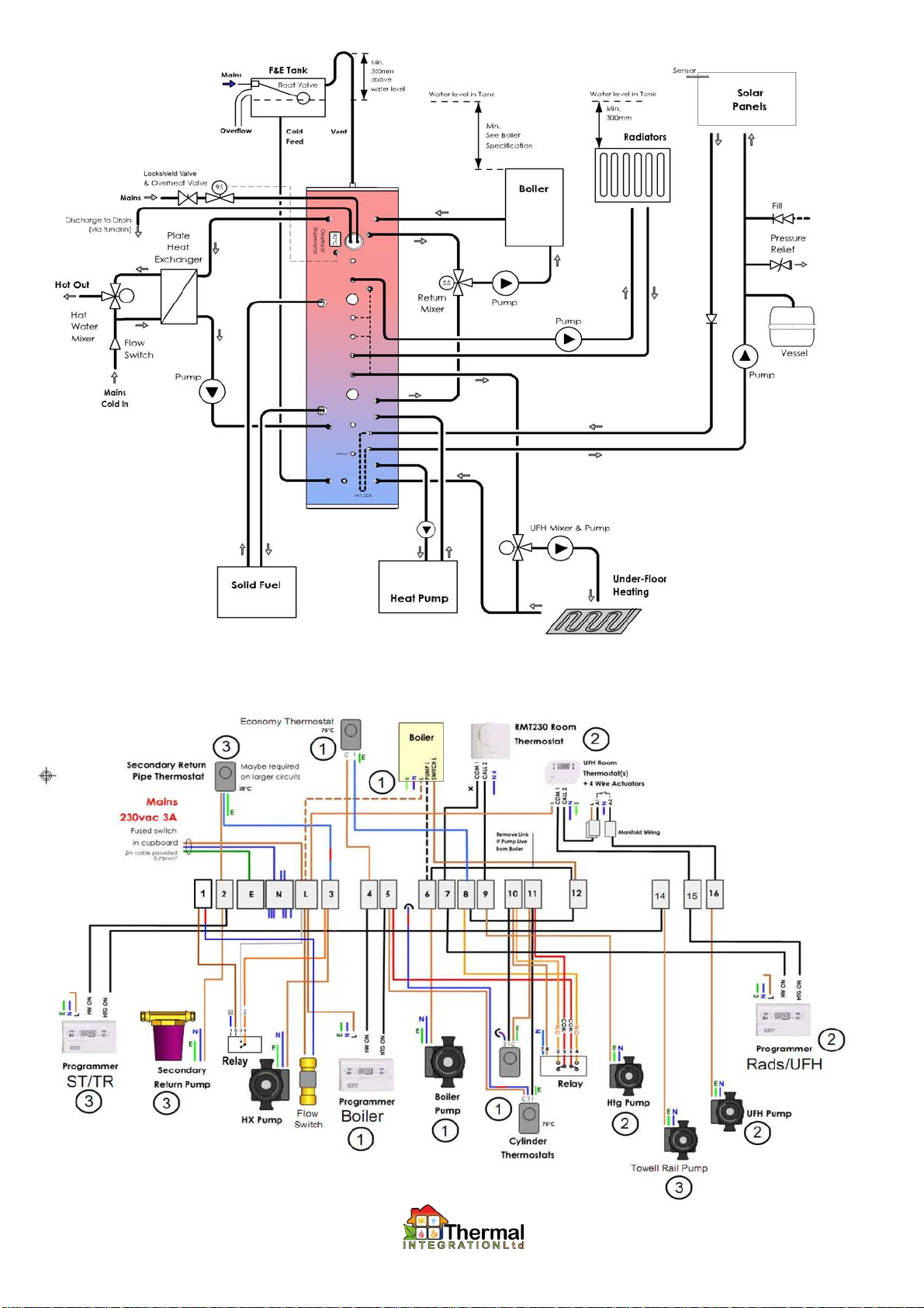
Fu Mu ti Fue Schematic:
Standard Wiring:
1 Boiler Control
2 Central Heating
3 Secondary Circulation

4
E ectrica Supp ies:
1. The Xcel Heat Bank (when fitted with any controls) requires a 3 Amp, 230v AC power supply, via a fused switched spur.
2. Power supplies to boilers and other equipment that has wiring connections, should be taken from the wiring centre on the Xcel.
3. The Xcel can be optionally supplied with 3kW, 6kW, or 9kW electric elements, with up to three elements in total. Power supplies should
be as follows
(a) For 3kW elements, a 16 Amp , 230v AC power supply, via a double-pole wall switch. 2.5mm2 heat resistant cable to be used.
Standard immersion heater controllers may be used as required.
(b) For 6kW elements, a 30 Amp , 230v AC power supply, via a double-pole wall switch and double-pole contactor linked to
thermostats, low water switch, and timer (if required). 4mm2 heat resistant cable to be used.
(c) For 9kW elements, a 45 Amp , 230v AC power supply, via a double-pole wall switch and double-pole contactor linked to
thermostats, low water switch, and timer. 6mm2 heat resistant cable to be used.
4. RCD/RCBO protection should be provided on all immersion heater supplies.
5. All supplies must be earthed, as well as all connections to immersion heaters.
6. Do not turn on power supplies to the controls or immersion heaters until the system has been filled with water.
7. When connecting to immersion heaters, press the reset button on the fitted overheat thermostat, and check that control thermostats are
set to 75°C (unless the design of the system calls for different temperature settings).
Making Push-Fit Connections:
1. Any soldered joints in adjoining pipework should be made prior to connection to adjoining push-tit connections.
2. Cut tube square using a rotary pipe cutter - do not use a hacksaw to cut the tube.
3. Check that the end of the tube is free from burrs and sharp edges or damage will occur to the O-Ring seals.
4. Allow 27mm of pipe for insertion into the fitting plus 10mm of pipe to allow use of a disconnecting tool.
5. Insert the tube through the release collar of the fitting to rest against the grab ring.
6. Push the tube in firmly until it reaches the tube stop.
5
Feed and Expansion Tank:
1. Feed and Expansion tanks should be sized to allow for suitable expansion of all primary water,
equal to 4% of the entire system volume, including cylinder and pipework. Allowance should be
made for cold fill level, and a minimum of 30mm from position of overflow, and 60mm from cold
inlet position. As a rule of thumb, pick a header tank with a capacity of 10% of system volume.
2. Where wood burners are connected to system, a metal feed and expansion tank should be used,
along with a copper float on inlet valve.
3. An overflow must be connected that is rated to 100°C, continually falling, and is capable of
discharging the full failure flow rate of the inlet valve (with float removed). This must be checked
during commissioning.
4. Feed and Expansion Tanks should be insulated.
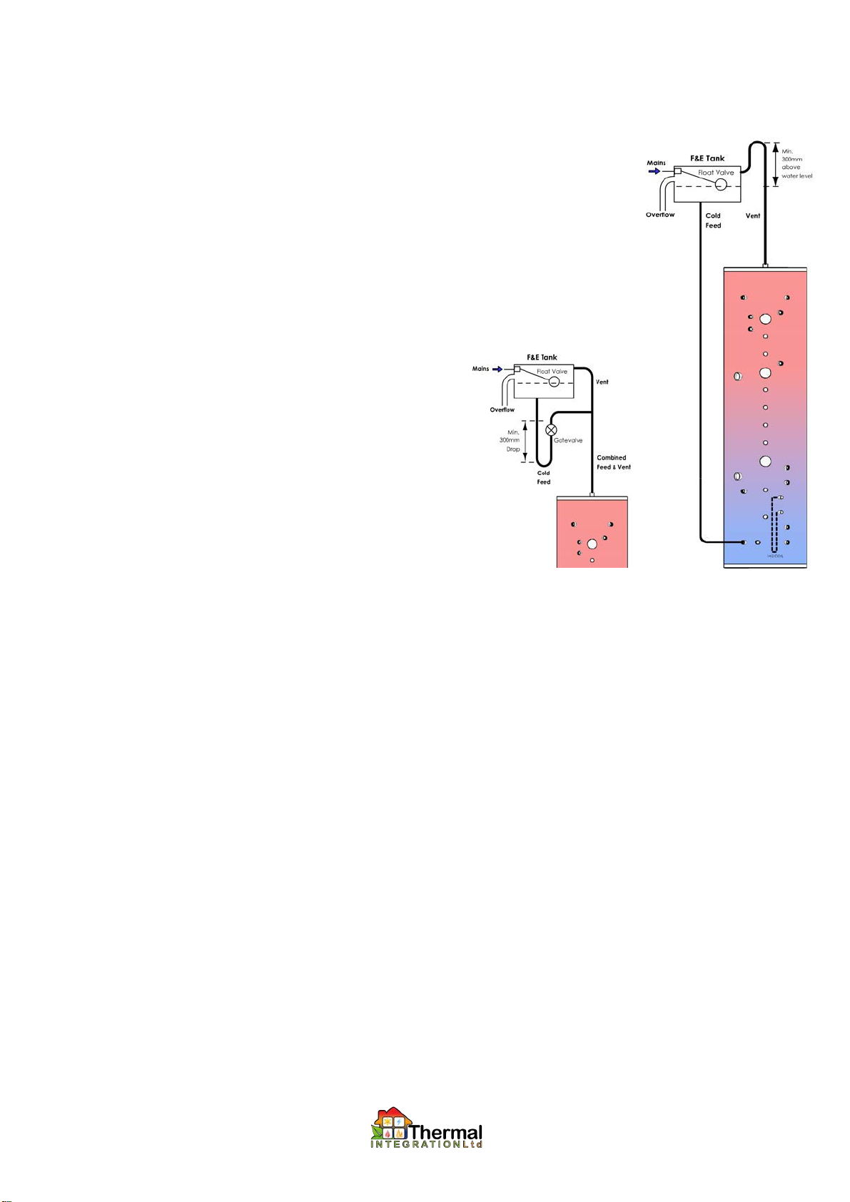
5. The vent pipe should be taken to a level 300mm higher than top of the F&E tank, before
connection through lid or into side at high level (30mm above overflow connection). If this is not
possible then it may be necessary to tee the cold feed into the vent
pipe (rather than the connection provided on the Xcel), via a return drop
of at least 300mm (see diagram).
6. Vent pipes must be continually rising from the Xcel. Horizontal runs
should have a slight incline.
7. Do not install separate vents, or cold feeds, at different points in a
system that shares flow. Any pumped flow will generate a pressure
difference along pipework, and this will cause circulation through the
F&E tank, heating it up, and mixing oxygen into the system,
accelerating system corrosion.
8. See Assembly X2009-19P for manually filled (no-discharge) systems.
9. Spare Parts
(a) Metal F&E Tank (400 litre systems) ........... 7067441
(b) Metal F&E Tank (800 litre systems) ........... 7067442
(c) Ball Float Valve
(d) Copper Float for float valve ....................... 7058763
(e) Tank Connector, 22mm Compression ....... 701022
Pressurised Storage Systems:
1. INSTALLATION AND MAINTENANCE OF PRESSURISED STORAGE SYSTEMS MUST BE DONE BY REGISTERED UNVENTED
PERSONS ONLY.
2. SYSTEMS MUST BE SERVICED ANUALLY, WITH ALL SAFETY VALVES TESTED.
3. SERVICING MUST BE RECORDED ON A LABEL SECURELY ATTACHED TO TORAGE UNIT.
4. SYSTEMS MUST NOT BE CONNECTED TO HEAT SOURCES (THAT CAN ACHIEVE > 90°C) WITHOUT THERMOSTATIC CONTROL,
OR WITHOUT THE FACILITY TO BE TURNED OFF VIA CONTROL THERMOSTATS, UNLESS SUITABLY APPROVED PROTECTION
HAVE BEEN PROVIDED.
5. DO NOT use O-Ring Seals on Immersion Heaters. If factory fitted then they should be replaced with PTFE string, and a fibre washer.
6. The following safety controls must be installed
(a) Expansion Vessel of size equal to, or greater than, 25% of total system volume, and having a pre-charge pressure between
0.9 and 1 bar.
(b) 2.5 bar Expansion Relief Valve, connected to a bottom (cold feed) connection on the Xcel, or adjoining pipework (without
possibility of isolation from the Xcel).
(c) 3 bar, 90°C Pressure and Temperature Relief Valve, connected directly to top (vent) connection on the Xcel.
(d) 1 bar RPZ (Reduced Pressure Zone) Automatic Filling Valve (requires discharge).
(e) Pressure Gauge and Temperature Gauge.
(f) Discharge pipe capable of removing the combined maximum discharge from all three safety valves.
7. Spare Parts
(a) Expansion Vessel, 80 litres ............................................................... 70101699
(b) Expansion Vessel, 80 litres. .............................................................. 70101700
(c) Expansion Vessel, 110 litres ............................................................. 7026118
(d) 2.5 bar Expansion Relief Valve ......................................................... 70674
(e) 3 bar, 90°C Pressure and Temperature Relief Valve ........................ 7069034
(f)
1 bar RPZ Automatic Filling Valve ..................................................... XVES
(g) Temperature and Pressure Gauge .................................................... 702308
(h) Temperature Gauge .......................................................................... 7014269
Straight Neck ...................................... 7068970
Swan Neck ......................................... 7059745
6
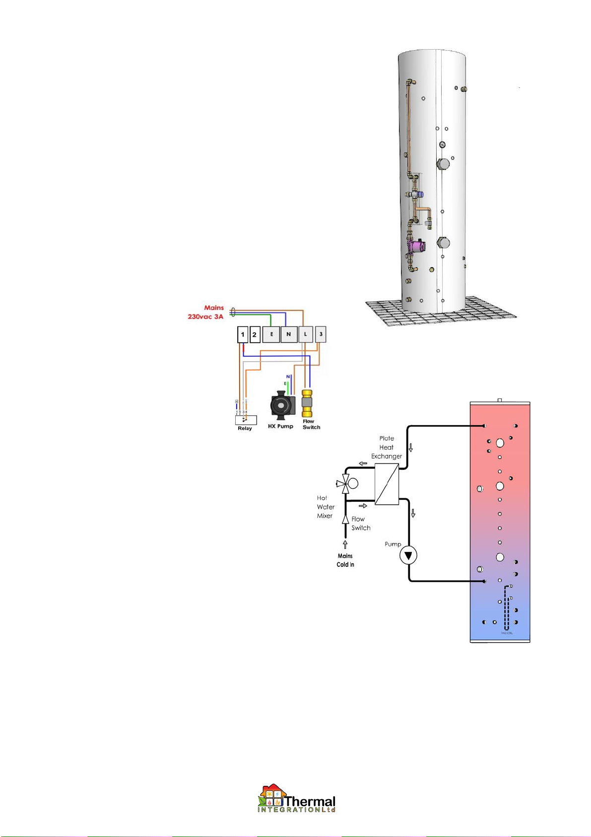
X2009-2: Mains Hot Water via P ate Heat Exchanger.
1. Please check that the maximum supply pressure does not exceed 6 bar, and if
necessary a Pressure Reducing Valve should be fitted onto the incoming
mains. Please ensure that all fittings and appliances connected to mains
supplies are rated at least 50% higher than supply pressure.
2. A Mains Isolating Valve must be fitted onto the incoming mains within the
cylinder cupboard within clear view.
3. A Y-Pattern Strainer (supplied loose) must be fitted onto the incoming mains.
The Y-Pattern Strainer should be fitted down-flow of the Isolating Valve in a
position to enable servicing.
4. In areas of hard water it is recommended that a Scale Inhibitor be fitted on the
incoming mains supply, and installed as per the manufacturers' instructions.
5. Although supply pressure may be as low as 0.1 bar, the flow rate performance
is relative to the supply pressures, and low supply pressures will result in poor
flow rates to taps.
6. A thermostatic mixing valve is supplied as standard for temperature limitation of
water supplied to outlets. This should be adjusted to users preference, and can
be locked to prevent tampering.
7. The circulating pump is factory set to speed 1. This can be turned up if flow
rates to hot taps need to be increased.
8. Pipework Connections
(a) Cold Mains In, 22mm.
(b) Hot Mains Out, 22mm.
9. Electrical
Connections factory
made.
10. Operation
(a) When a hot tap is opened, cold water passes
through the flow switch, plate heat exchanger and
thermostatic valve.
(b) The flow switch passes a live signal to the
circulating pump via the relay.
(c) Hot water is pumped into the heat exchanger from
the top of the Xcel, heating up the mains water
supplied to taps.
(d) When the tap is shut, the flow switch removes live
feed from the pump
11. Spare Parts
(a) Thermostatic Mixing Valve, 22mm .............. 70200015
(b) Thermostatic Mixing Valve, 28mm .............. 70200004
(c) Circulating Pump ........................................ 70200226
(d) Flow Switch (Must be fitted with Relay)..... 702307
When connecting the cold mains water supply to the flow switch, care must be taken how the work is done.
It is important that the pipework is installed such that the body of the flow switch sits vertically to ensure
that it operates satisfactorily. If it sits out of line from the vertical, it may cause the switch to activate inconsistently
and fail to run the heat exchanger pump
(e) Relay............................................................ 7069689
7
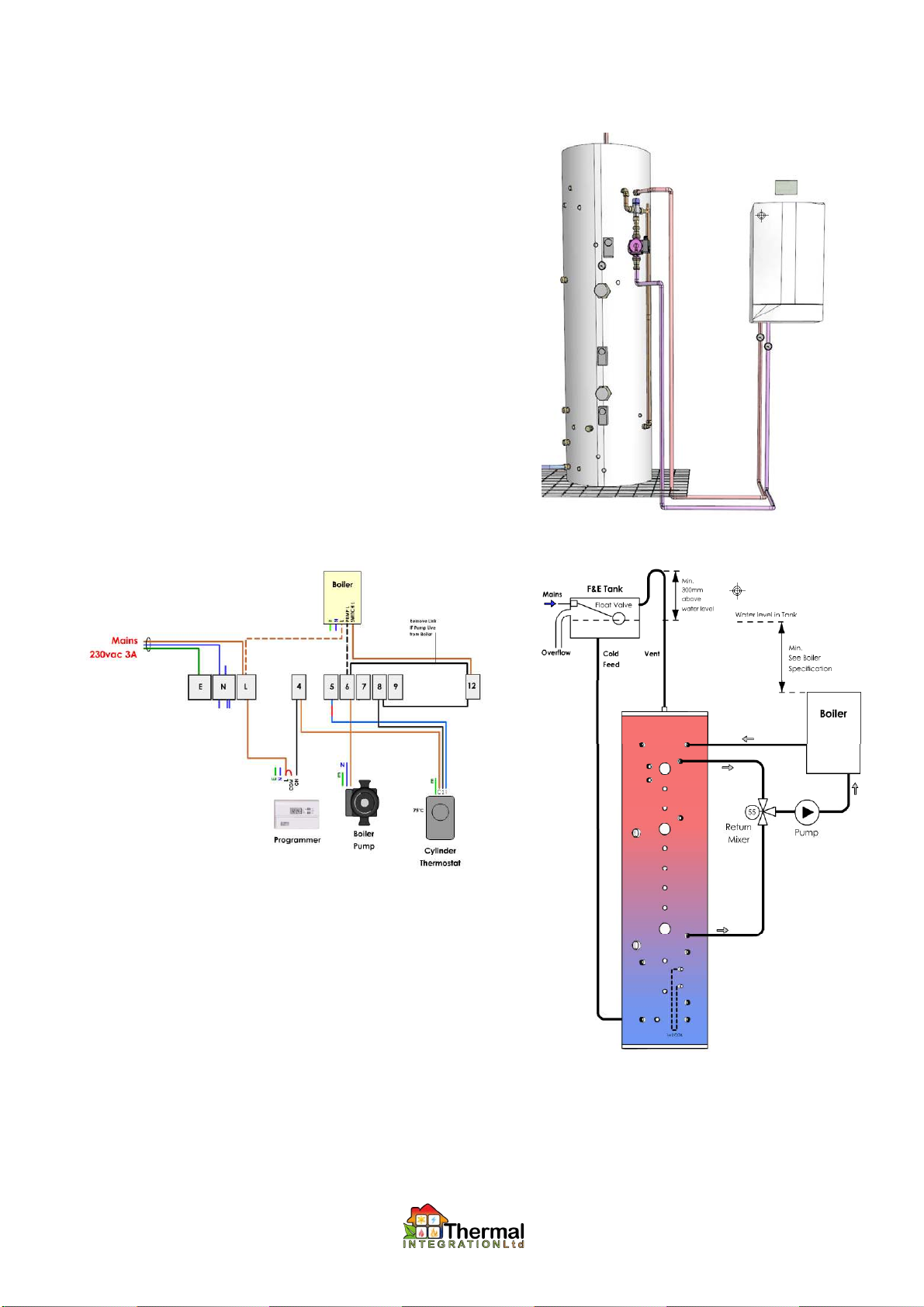
X2009-5: Direct Boi er Connection, GX System, 35kW.
See Also 11B/12B (Pumps) and 6,7 (Thermostats)
1. Suitable for connection of boilers up to 35kW output.
2. If output of boiler exceeds 35kW, assembly X2009-5A is required
instead.
3. The lower return connection from the Xcel to the Boiler is taken from
above the solar coil as standard. To enable the boiler to heat the entire
store (including solar section), then the return connection needs to be
reconnected lower down, and cylinder thermostats need lowering.
4. It assists in commissioning, and fault-finding, to install temperature
gauges on boiler flow and return pipes.
5. If the Xcel is installed as a vented system, and the boiler is only
suitable for pressurised systems, then a plate heat exchanger will need
to be installed to isolate boiler from vented storage system.
6. The circulating pump is factory set to speed 3. This can be adjusted to
obtain a temperature drop across boiler of 15 to 20°C.
7. Return temperature to boiler should ideally be 55°C, with an 18°C
temperature rise, to achieve a 73°C flow temperature.
8. Boiler control thermostat should generally be left on maximum.
9. Pipework Connections
(a) Return top Boiler, 28mm.
(b) Flow from Boiler, 28mm.
10. Electrical Connections (Single Thermostat)
11. Operation
(a) When cylinder thermostats call for heat, a live feed is provided to boiler,
and boiler pump.
(b) The boiler fires, and water is re-circulated by the return mixer from the top
of the Xcel, through the boiler, and back to the top of the Xcel.
(c) Once the top of the Xcel reaches > 55°C, the return mixer starts drawing
from the base connection to the Xcel, to regulate return temperature.
(d) Xcel heats up from the top-downwards, until cylinder thermostats are
satisfied, and live feed to boiler is removed.
(e) Boiler pump may keep running for a short period following boiler turn-off.
12. Spare Parts
(a) Return Mixing Valve, 28mm ............................. 70200001
(b) Circulating Pump [X2009-11B] ....................... 70200226
(c) High Flow Circulating Pump [X2009-12B] ...... 70200124
8
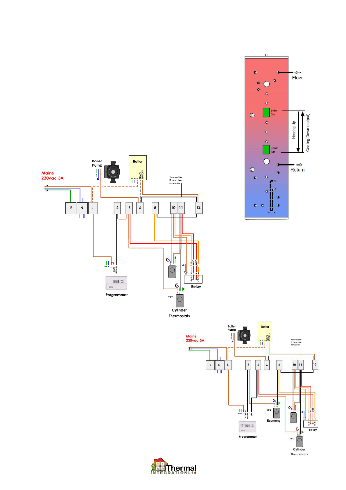
X2009-7: Thermostat and Re ay for Buffering Boi er Input.
X2009-8: Thermostat for Boi er Contro (economy mode). (see X2009-18A)
1. The use of two thermostats linked with a relay allows the thermostats to act as a latch, with one
thermostat acting as the switch on, and the other as the switch off. This is used to hold off firing
of the boiler until there is a known volume of water at a low enough temperature to call for the
boiler to fire.
2. Once fired, the boiler will continue to fire until the off thermostat is satisfied.
3. Additional cylinder thermostats can provide reheating to set positions on the store (assuming
top-down reheating). Thermostats located at the top of the Xcel can provide an economy mode,
heating up small quantities of hot water for low-medium hot water demand. Thermostats located
at base of the Xcel can provide a heavy demand mode, where the entire volume of the store is
heated.
4. Additional switching will be required for each thermostat used, either by a wall mounted switch,
or using a timer or programmer.
5. Electrical Connections (X2009-7 only)
6. Electrical Connections (X2009-7 and -8)
7. Spare Parts
(a) Danfoss Randall ITC 100 thermostat .................. 7025442
(b) Relay .................................................................... 702315

COM
Volt-Free Call
Volt-Free Call
COM
Volt-Free Call
Volt-Free Call
1 5 3 4
Note: The preceding thermostat options (X2009-5; -7; -8) are intended to provide a switched live 230Vac signal to call a
gas / oil fired boiler, or similar heat source, to fire. In the case of appliances that required a volt-free / clean contact call
(e.g. MCZ pellet boilers and stoves), the call out from the cylinder thermostat/s must be passed via a relay. This can be
retrospectively fitted during installation (part no: X2009-2 RELAY can be obtained for this purpose).
Alternatively, The following pre-wired thermostat options provide this facility if the unit has been ordered with them:
X2009-8P-VF: Single Thermostat for Volt-Free Boiler Input
1. Pre-wired single thermostat, suitable for use with any boiler that requires a volt-free / clean contact call to fire.
2. Comprises pre-wired thermostat only: Does not include pre-plumbed GX assembly.
3. Wiring includes a single pole relay that gives volt-fee switched call for heat.
4. Electrical connections:
X2009-7-VF: Thermostat and Relay for Volt-Free Buffering Boiler Input
1. Pre-wired twin thermostats suitable for use with any boiler that requires a volt-fee / clean contact call to fire
2. Comprises pre-wired thermostats only: does not include pre-plumbed GX assembly.
3. Wiring includes a double pole relay that provides latching circuit for buffered operation (as per X2009-7), and also gives
volt-free switched call for heat.
4. Mode of operation is as per X2009-7
5. Electrical connections:
9
10
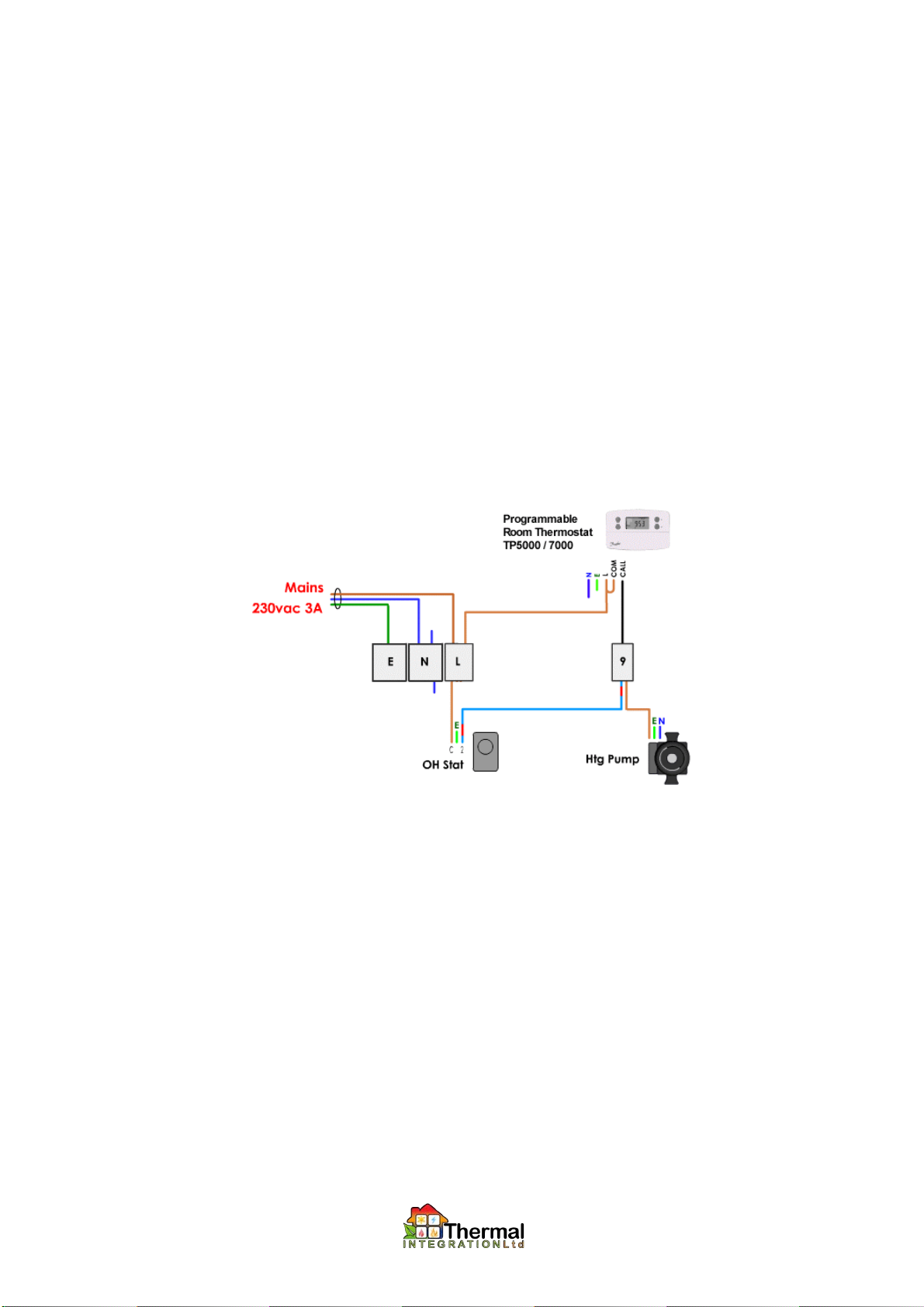
X2009-9: Overheat Thermostat.
1. The overheat thermostat is wired to pass a live to a central heating pump to initiate central heating once the stored water reaches 90°C,
thereby cooling the store and preventing overheating due to continued heat input from wood burners or solar panels.
2.
If motorised valves or actuators are fitted on heating circuits, then the overheat thermostat must be wired so as to open the appropriate
valve(s) and initiate the circulation pump for the overheat dump circuit.
3. Ensure that the dump heating circuit is capable of removing enough heat from the system. This will depend on the type of appliance that
overheat protection is provided for. In the case of wood burners without thermostatic control, this can be between 3 and 30kW depending
on model and type of fuel used.
4. Ensure that any fitted radiator thermostats or room thermostats do not prevent transfer of heat, even when rooms are up to temperature.
Some radiators may have to be left without thermostatic valves.
5. Room thermostats are by-passed as shown in wiring diagram below.
6. The temperature setting on the overheat thermostat may be lowered if it is desirable to have central heating start automatically when the
store reaches a specified temperature.
7.
When dumping heat into an underfloor heating system, it will be necessary to integrate with the type of underfloor heating controls that
are used. It is generally necessary to simulate both a call for heating and short-circuit the room thermostats of the zones to be dumped to,
and may require the use of additional relays. For further help, please contact the TI technical department, providing detailed
information on the UFH wiring.
8. This option is often used in conjunction with Option X2009-13 Power-free overheat protection via discharge.
9. Electrical Connections (Standard Radiator Circuit with Programmable Room Thermostat and Overheat)
10. Spare Parts
(a) Danfoss Randall ITC 100 thermostat .................. 7025442

11
X2009-13: Overheat Discharge to Drain.
1. The overheat discharge system uses a mechanical
thermostatic valve to discharge water to drain via a coil in
the Xcel, thereby cooling stored water and preventing
overheat.
2. The discharge valve is factory set to 95°C and cannot be
adjusted.
3. A pressure reducing valve, set less than 1 bar, should be
fitted up-flow of the discharge valve to maintain
calibration.
4. The discharge pipe should be run in 15mm pipe, 100°C
rated, before final discharge via an air-break, typically
using a Tundish.
5. The discharge valve is fitted with a manual test facility.
Function of the valve should be tested during
commissioning, and annually thereafter.
6. Spare Parts
(a) Overheat Discharge Valve................................................................... 70101675
(b) Pressure Reducing Lockshield Valve, 15mm ...................................... 7016968
(c) Retro-Fit Overheat Coil ....................................................................... 7066429

12
X2009-18A: Two Channe Programmer for using Economy/Norma Recovery modes.
1. Where option X2009-8 is chosen to add Economy Mode to your Xcel Heat Bank, an additional cylinder thermostat is provided to allow
smaller quantities of hot water to be heated using the boiler. Option X2009-18A provides a two-channel programmer that allows you to
easily control when the boiler should run in economy mode, and when the boiler should heat the entire store.
2. Channel 1 is used to set times when economy mode is to be used.
3. Channel 2 is used to set times when normal mode is to be used.
4. If both channels are on at the same time, economy mode is ignored.
5. In economy mode, the boiler typically heats up the top 25% of the store. The position of the economy mode thermostat can be altered to
increase/decrease the amount of water heated up in economy mode.
6. Economy mode will provide enough hot water to run sinks, basins, a bath, or one or two showers, and can keep taps running as long as
required (in a similar fashion to a combination boiler).
7. Economy mode will not provide enough stored hot water to run multiple baths or showers at the same time (unless water is also being
heated by an alternative heat source), and will not provide central heating.
8. The economy mode should be used as standard where the Xcel is connected to alternative heat sources such as wood burners or solar
panels. This ensures that the majority of the water in the Xcel is not heated by the boiler and can therefore be used for storing heat from
the alternative sources.
9. Standard mode should be typically used as a timed boost to heat up the whole store in advance of known heavy draw-off periods. This
way you can be sure that there is enough water ready when needed. Alternatively the +1hr Boost facility can be used to generate higher
volumes of hot water as needed.
10. Electrical Connections
11. Spare Parts
(a) Danfoss FP715 Two Channel Programmer.................... 7026643
13
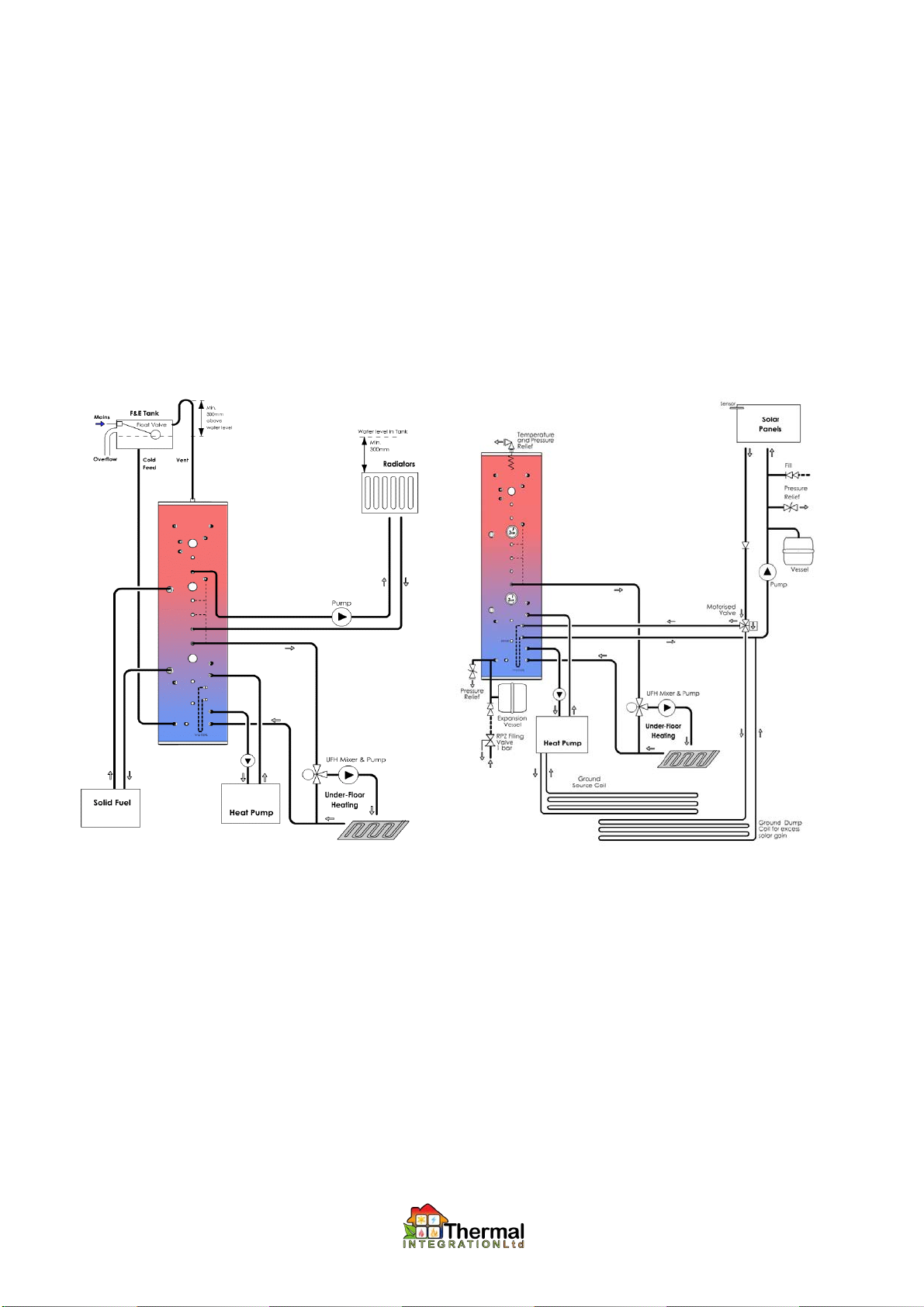
Integration with Heat Pump Systems:
1. The Xcel Heat Bank can act as a buffer between a heat pump and the central heating system, allowing heat pump to be combined with
other heat sources for both hot water and heating.
2. Heat pumps are generally connected into the lower half on the Xcel, with higher temperature heat sources (wood burners, gas boilers)
using the upper half of the store. It is important to keep the heat pump cold return connection from low down.
3. Where a heat pump is integrated in a vented Xcel storage system, it may be necessary to remove any low-pressure safety switches in the
heat pump, and replace with a flow switch. Consult heat pump manufacturer.
4. To reduce turbulence in the stored water, caused by high flow heat pump circuits, Diffuser Tubes can be supplied on request.
5. To improve performance due to low storage temperatures, a number of higher duty plate heat exchangers are available for generating
mains hot water. See section on Plate Heat Exchanger Performance.
6. Sample Schematics
(a) Solid Fuel combined with Heat Pump on a vented s stem. (b) Solar combined with Heat Pump on pressurised s stem.

14
Examp e Schematic, Wood Burner on Gravity:
1. For use with Wood Burners installed where gravity circulation is possible.
2. Overheat protection is not detailed in top schematic, and should be provided from Xcel.
3. This is the simplest form of connection of a wood burner, and the most often used.
4. The Xcel is provided with two 1½” Bosses for connection of pipework up to 42mm, is required.
5. Read in conjunction with section on X2009-13: Overheat Discharge to Drain.

15
Examp e Schematic, Wood Burner Pumped/Gravity:
1. For use with Wood Burners installed where gravity
circulation is possible, and pumped operation is also
desirable.
2. Overheat protection is not detailed in top schematic, and
should be provided from Xcel.
3. The Gravity Valve allows gravity circulation to operation in
conjunction with a pumped flow.
4. The Return Mixer re-circulates water through wood burner
until temperatures reach 60°C, preventing low flue
temperatures that result in deposits.
5. Read in conjunction with section on X2009-13: Overheat
Discharge to Drain.
7. Spare Parts
(a) Return Mixer 1” ........................................... 70200001
(b) Pump ........................................................... 70200226
(larger duty pumps on request)
(c) Three-Port Gravity Valve 1”MBSP .............. 70WBA-13A
(d) Flue Thermostat .......................................... 70200077
PUMPED/ GRAVITY EXAMPLE

8. Electrical Connections
(a) The wood burner circulating pump can be controlled
using a
flue thermostat fitted as shown below. The thermostat should be set
to a temperature that engages the pump once combustion is well
established (e.g. 100 - 120 Degrees C or higher).
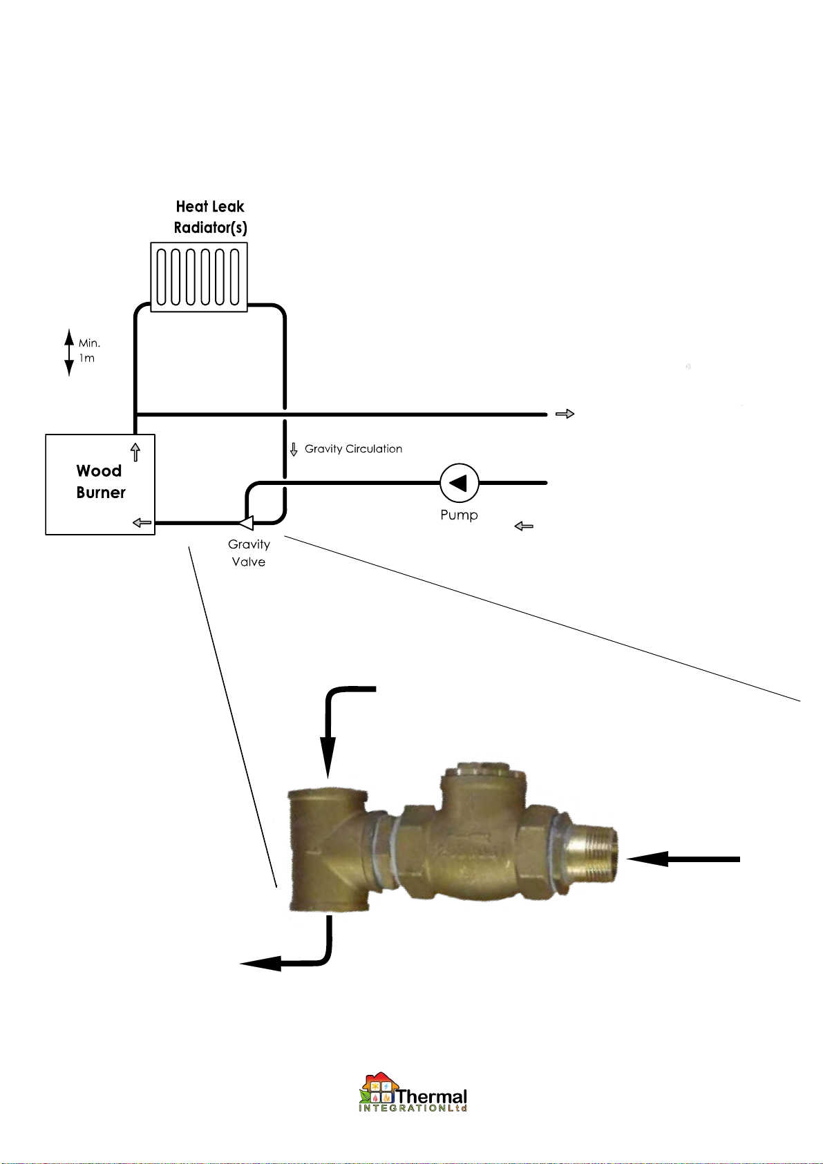
16
Examp e Schematic, Wood Burner Pumped/Gravity:
1. For use with Wood Burners installed where gravity circulation is not possible, and a dump radiator can be uinstalled for
overheat protction.
2.
3. Overheat protection is not detailed in top schematic, and should be provided from Xcel.
4. The Gravity Valve allows gravity circulation to operation in conjunction with a pumped flow.
5. The Return Mixer re-circulates water through wood burner until temperatures reach 61°C, preventing low flue temperatures
that result in deposits.
6. A balancing valve must be fitted onto the hot inlet to the mixing valve, and should be set to pass the minimum flow
permissible for the wood burner (typically 5 litres/ minute).
7. Read in conjunction with section on X2009-13: Overheat Discharge to Drain.
8. Spare Parts
(a) Return Mixer 1” ........................................... 70200001
(b) Pump ........................................................... 70200226
(larger duty pumps on request)
(c) Three-Port Gravity Valve 1”MBSP .............. 70WBA-13A
(d) Flue Thermostat .......................................... 70200077
17
FULLY PUMPED EXAMPLE
Pumped flow to thermal store
Pumped return from thermal store
Installation of gravity swing check valve on pumped wood burner
with gravity heatleak radiator
Return from Thermal Store
(Pumped)
Return from Heat Leak circuit
(Gravity
Return to Wood Burner

18
Examp e Schematic, Wood Burner remote from Xce :
1. For use with Wood Burners installed where gravity circulation is not possible, and a heat leak radiator is impractical.
2. Heat Leak Plate Heat Exchanger provides overheat protection, during pump or power failure.
3. Cold mains water is passed through the heat exchanger when the wood burner achieved 94°C. The mains water cools the
gravity circuit above the wood burner, and is then discharged to drain.
4. The Gravity Valve prevents unwanted heat leak.
5. The Return Mixer re-circulates water through wood burner until temperatures reach 61°C, preventing low flue temperatures
that result in deposits.
6. A balancing valve must be fitted onto the hot inlet to the mixing valve, and should be set to pass the minimum flow
permissible for the wood burner on start-up (typically 5 litres/ minute).
7. Read in conjunction with section on X2009-13: Overheat Discharge to Drain.
8. Spare Parts
(e) Overheat Discharge Valve........................... 70101675
(a) Return Mixer 1” ........................................... 70200001
(b) Pump ........................................................... 70200226
(larger duty pumps on request)
(c) Three-Port Gravity Valve 1”MBSP .............. 70WBA-13A
(d) Flue Thermostat .......................................... 70200077

19
Examp e Schematic, Wood Burner above Xce :
1. For use with Four-Port Wood Thermostatic Burners.
2. Heat Leak Radiator provides overheat protection, during
pump or power failure.
3. The Gravity Valve prevents unwanted heat leak.
4. The Return Mixer re-circulates water through wood burner
until temperatures reach 61°C, preventing low flue
temperatures that result in deposits.
5. A balancing valve must be fitted onto the hot inlet to the
mixing valve, and should be set to pass the minimum flow
permissible for the wood burner on start-up (typically 5 litres/
minute).
6. Spare Parts
(a) Return Mixer 1” ........................................... 70200001
(b) Pump ........................................................... 70200226
(larger duty pumps on request)
(c) Three-Port Gravity Valve 1”MBSP .............. 70WBA-13A
(d) Flue Thermostat .......................................... 70200077

20
IC8x40 P ate Heat Exchanger Specifications: (used in assemblies X2009 -2, -4, -8)
BT12x40 P ate Heat Exchanger Specifications: (used in assemblies X2009 –2A)
Tab e of Heat Losses from Uninsu ated Copper Pipe:
1. This table highlights the importance of insulating pipework.
Heat loss for fluid inside pipe
(W/m) (Btu/hr.ft)
Nominal bore
Temperature difference (oC) Temperature difference (oF)
(mm) (inches) 22 38 55 70 100 130
15 1/2 21 32 45 22 34 47
22 3/4 28 43 60 29 45 53
28 1 34 53 76 36 56 79
35 1 1/4 41 64 89 43 67 93
42 1 1/2 47 74 104 49 77 108
54 2 59 93 131 62 97 136
67 2 1/2 71 111 156 74 116 162
76 3 83 129 181 87 135 189
108 4 107 165 232 111 172 241
Insta ation Notes
Table of contents
Popular Heater manuals by other brands


Heatwagon
Heatwagon 4200 Installation and maintenance manual

Co-op
Co-op C30C owner's manual

VOGEL&NOOT
VOGEL&NOOT DELLA WAVE Assembly and operating manual

Firesense
Firesense LPG Series manual

Thomas&Betts
Thomas&Betts REZNOR V3 Series Installation & operation

MrHeater
MrHeater HEATSTAR MHU100NGPALP installation instructions