Thermaltronics TMT-HA600 Series User manual

USER MANUAL
TMT-HA600
HOT AIR TOOL
www.thermaltronics.com


WARRANTY
All equipment and accessories are warranted by Thermaltronics to be free from
defects in materials and workmanship as follows:
Part Number Description Warranty Period
TMT-HA600-1 100-110V Hot Air Tool 1 Year
TMT-HA600-2 220-240V Hot Air Tool 1 Year
HA-HE600-1 100-110V Heating Element 30 Days
HA-HE600-2 220-240V Heating Element 30 Days
This warranty does not apply to equipment or goods which have been tampered
with, misused, damaged through improper installation or used in a manner
contrary to supplier instructions. Normal “wear and tear” of equipment or goods
is not covered by this warranty. If the product should become defective within the
warranty period, Thermaltronics will repair or replace it free of charge at its sole
option. Warranty period is from the date of purchase by the original owner. If the
date of purchase cannot be substantiated the date of manufacture will be used as
the start of the warranty period.
TABLE OF CONTENTS
TMT-HA600 SPECIFICATIONS ................................................................... 1
INTRODUCTION.......................................................................................... 1
SYSTEM FEATURES................................................................................... 1
SAFETY PRECAUTIONS............................................................................. 2
SYSTEM PANEL, FRONT PANEL ............................................................... 3
UNPACKING/ASSEMBLY/OPERATION ...................................................... 4
SYSTEM SETTINGS.................................................................................... 5
FREQUENTLY ASKED QUESTIONS .......................................................... 6
ORDERING GUIDE...................................................................................... 7
WARNING:
This appliance is not intended for use by persons (including children) with reduced physical, sensory or mental
capabilities, or lack of experience and knowledge, unless they have been given supervision or instruction
concerning use of the appliance by a person responsible for their safety.
Children should be supervised to ensure that they do not play with the appliance.
This tool must be placed on its stand when not in use.

1TMT-HA600 Hot Air Tool
USER MANUAL
TMT-HA600 SPECIFICATIONS
Input Line Voltage: TMT-HA600-1 100-110 VAC
TMT-HA600-2 220-240 VAC
Power: 1300 Watts
Temperature Range: 100C - 480C (212F - 896F)
Pump: Diaphragm
Air Flow (Max): 23L / min
Fuse: TMT-HA600-1 250V 15A
TMT-HA600-2 250V 8A
Size (W x H x D): 188mm x 127mm x 246mm
Weight: 3 KG
Certication Marks: CE, ETL
INTRODUCTION
Congratulations on your purchase of the TMT-HA600 hot air tool. This unit
has been tested and inspected by Thermaltronics prior to shipment, and with
proper maintenance will give you years of reliable performance.
SYSTEM FEATURES
The TMT-HA600 hot air tool can be used for surface mount component
removal and reow on components such as SOIC, CHIP, QFP, PLCC and
others.
1. Digital display shows temperature and status.
2. Airow meter provides visual feedback of air ow.
3. 1300W high power heater designed to work on very difcult applications,
in the removal and reow of surface mount components.
4. Large selection of high quality nozzles for rework on QFP, SOP, PLCC and
SOJ components.
Functions and Features

2
SAFETY PRECAUTIONS
Warning
A fire may result if this equipment is not used with care and for intended
applications. To avoid electric shock or injury, please follow the instructions
below strictly:
1. The unit must be properly grounded.
2. The unit can reach extremely high temperatures when switched ON.
- Do not use the device near ammable materials or gases
- Do not touch heated parts, which can cause severe burns
- Do not point the nozzle towards any part of the body
3. Never operate the equipment with wet hands.
4. Always disconnect the power cord and allow the unit ample time to
cooldown before performing maintenance.
5. Use only genuine replacement parts.
Caution
1. Use this equipment in a well-ventilated area, away from combustible
equipment.
2. Disconnect the power cord if the unit is not used for an extended period of
time.
3. Place handle in stand when not in use.
4. Handle with care.
- Never drop or sharply jolt the unit.
- The unit contains delicate parts that can be damaged if subjected to
physical force.
- Do not spill any liquids into the unit.
5. Do not operate on uneven surfaces.
6. Allow to cool down before storage.
7. Turn off the power when the unit is not in use.
8. Do not alter the unit in any manner.
9. When resting the handle in the handle holder, make sure there are no
objects within 30cm of the nozzle, as nearby objects maybe damaged.
10. Do not apply excessive force when installing and removing nozzles.
11. Do not use pliers to pull the edges of the nozzle.
12. Do not over tighten the screw when installing a new nozzle.

3TMT-HA600 Hot Air Tool
USER MANUAL
FRONT PANEL
(d) Air Flow Control
(c) Temperature Control
Air Flow Meter
(a) Temperature Display
(e) Function Button
(b) Air Flow Display
SYSTEM PANEL
Power Switch
Handpiece Holder
Hot Air Gun
Front Panel
External Fuse
Front Panel
(a) Temperature Display - Shows the set and actual temperature in Celsius or Fahrenheit
(b) Air Flow Display - Shows the air ow
(c) Temperature Control - Increase or Decrease the set temperature.
● Temperature Range in Celsius - 100C to 480C
● Temperature Range in Fahrenheit - 212F to 896F
(d) Air Flow Control - Increase or Decrease the set air ow (range 15-99)
(e) Function Button - Toggle the hot air tool between standby mode or operating mode. In System
Settings, the button can be used to save settings. (see: System Settings)
● "On" = Pushed Down Position, "Off" = Popped Up Position

4
UNPACKING/ASSEMBLY/OPERATION
Please read this manual and follow the directions before using the equipment. The carton contains:
1. TMT-HA600 Hot Air Tool
2. HTN-D50, HTN-D80, HTN-D100, HTN-D120 nozzles
3. HA-HE600 Heating Element
4. Vacuum Suction Pen
5. Power Cord
Important: Keep all shipping materials until satisfactory operation has been veried.
Assembly and Operation
1. Remove TMT-HA600 Hot Air Tool from its box and place on a suitable work bench.
2. Remove the screw on the bottom of the unit marked in red wax. This screw is used to prevent the air pump from
moving during shipping. Warning: Failure to remove the screw before using the equipment can cause
damage to the system.
3. Select the proper nozzle and secure it to the handle.
4. Ensure the hot air gun is placed in the handpiece holder. (see Operation - Auto-Sleep Mode)
5. Connect the AC plug to a suitable AC power outlet.
6. Switch the power switch on the back of the unit to the “on” position.
7. To start rework push down the (e) Function Button into the "on" position (see Front Panel).
8. Lift the hot air gun from the holder
9. Adjust the air ow level using the (d) Air Flow Control (see Front Panel).
10. Adjust the temperature level using the (c) Temperature Control (see Front Panel). The (a) Temperature
Display will change from showing the actual temperature to the set temperature while the temperature is being
adjusted. After temperature adjustment is done, the Temperature Display will revert back to showing the actual
temperature rather then the display temperature.
11. Wait for the actual temperature to reach the set temperature. The unit should then be ready.
Operation - Power Off
1. Place the hot air gun back into the holder.
2. Press the (e) Function Button (see Front Panel). This will start the auto cool
process to accelerate cooling down the hot air gun. The display will show "OFF" once the
heating element temperature has gone down below 80C (176F).
3. Switch off the unit.
4. Unplug if not used for extended periods of time.
Operation - Auto-Sleep Mode
1. Once the hot air gun has been placed into the holder, the hot air gun will automatically go into standby mode
once the sleep timer setting (default: 5 minutes) has been reached.
2. To wake the hot air gun from sleep mode, lift the hot air gun from it's holder or press any control button.
Note: To ensure that the auto-sleep mode is activated, the hot air gun must be properly placed into the
holder. The letter "L" will show next to the temperature indicating the hot air gun is "Locked".
(a) place the handle onto
the holder
(b) pull the handle downwards
to secure in place
(c) Handle in locked position

5TMT-HA600 Hot Air Tool
USER MANUAL
SYSTEM SETTINGS
System Settings - Enter Menu
The system settings menu can be accessed by following the procedure below:
1. Turn off unit.
2. Ensure that the (e) Function Button is in the "on" position (pushed down).
3. Switch the power switch on the back of the unit to the “on” position.
4. While the letters “ESD SAFE” are scrolling across the display, simultaneously press and hold both (c)
Temperature Control up and down buttons (see Front Panel).
5. If successful the digital display will show “SEL 1” (Select 1).
Selection Menu Function
1 Hot Air Gun Sleep Timer
2Temperature Scale Adjustment
3 AC Line Frequency Selection
4 Hot Air Gun Temperature Calibration
System Settings - Hot Air Gun Sleep Timer
Once the hot air gun is placed into the holder. The system will go into sleep mode once the sleep timer has been
reached (default is 5 minutes). Use the following procedure to set the sleep timer:
1. Follow System Settings - Enter Menu procedures.
2. Use the (d) Air Flow Control down button to adjust system selection menu to SEL 1.
3. Press the (d) Air Flow Control up button to conrm the selection.
4. The display will show “t" (timer) and x (x = minutes). The sleep timer is adjustable from 5 to 60 minutes with "off"
representing the auto-sleep mode is turned off.
5. Press the (d) Air Flow Control up and down buttons to adjust the sleep timer.
6. To save the selected settings and exit from the menu press the (e) Function Button.
System Settings - Temperature Scale Adjustment
By default, the temperature scale has been set by the factory. For manual override follow the procedure below:
1. Follow System Settings - Enter Menu procedures.
2. Use the (d) Air Flow Control down button to adjust system selection menu to SEL 2.
3. Press the (d) Air Flow Control up button to conrm the selection.
4. The display will show "c" (celsius) or "f" (fahrenheit).
5. Press the (d) Air Flow Control up and down buttons to adjust the temperature scale.
6. To save the selected settings and exit from the menu press the (e) Function Button.
System Settings - AC Line Frequency Selection
By default, the line frequency has been set by the factory. For manual override follow the procedure below:
1. Follow System Settings - Enter Menu procedures.
2. Use the (d) Air Flow Control down button to adjust system selection menu to SEL 3.
3. Press the (d) Air Flow Control up button to conrm the selection.
4. The display will show "-50" (50 Hz) or "-60" (60 Hz).
5. Press the (d) Air Flow Control up and down buttons to adjust the AC Line Frequency.
6. To save the selected settings and exit from the menu press the (e) Function Button.
System Settings - Hot Air Gun Temperature Calibration
By default, the temperature calibration has been set by the factory. For manual override follow the procedure below:
1. Follow System Settings - Enter Menu procedures.
2. Use the (d) Air Flow Control down button to adjust system selection menu to SEL 4.
3. Press the (d) Air Flow Control up button to conrm the selection.
4. The display will show "Add XXX" or "Sub XXX". (Add = add offset, Sub = subtract offset, XXX = temp. offset)
5. Press the (d) Air Flow Control up and down buttons to adjust the temperature offset.
6. To save the selected settings and exit from the menu press the (e) Function Button.

6
FREQUENTLY ASKED QUESTIONS
Q: The unit has no power.
A: Check if the unit is switched on and the power cord is plugged in. Verify that the
fuse has not blown out. Pick up the hot air gun, the unit may just be in sleep mode.
Q: The unit is very noisy and vibrating too much.
A: Verify that the shipping screw on the bottom of the unit marked in red wax has been
removed.
Q: The actual temperature is not increasing.
A: Pick up the hot air gun, the unit may just be in sleep mode. The overheat protection
may be engaged, power off unit to cooldown and then power back on. Lastly, check if
the heating element is damaged, replace if damaged.
Q: Temperature display is always above 500, after a few minutes the display
shows "Off".
A: The thermal sensor may be broken and needs to be replaced.
Q: Replacing the heating element.
Caution: Disconnect power before replacing heater element.
1. Remove the three screws holding the heater pipe in place.
2. Pull back the air tube from the back of the hot air gun
3. Push forcefully up on the inner tube to unseat the internal
heating assembly from the outer shaft.
4. Disconnect the heater connector, pull back the heat shrink
tube and desolder thermocouple wires.
5. Insert a new heating element (HA-HE600).
6. Reassemble the hot air gun in the reverse order it was
disassembled.
Note: Ensure the ground wire is properly connected to the
heater pipe.
1
2
3
Q: Other problems
4
36
7
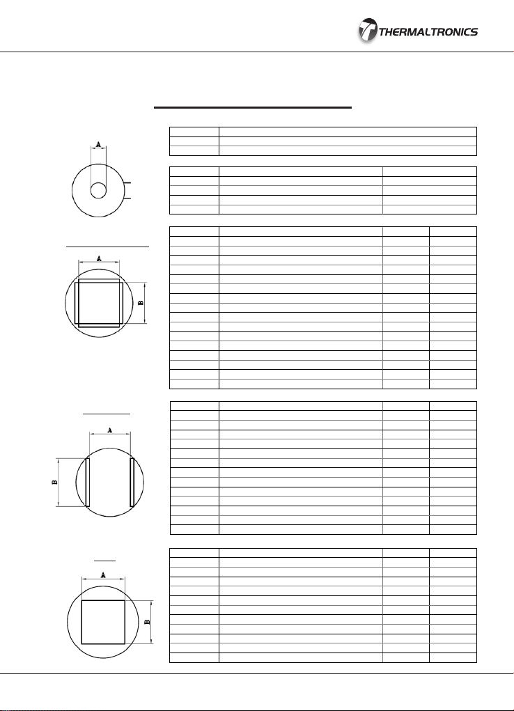
ORDERING GUIDE
SPARE PARTS & NOZZLES
PART# DESCRIPTION A mm (in) B mm (in)
HTN-PL20 Nozzle 11.9mm x 11.9mm, PLCC-20 11.9 11.9
HTN-PL28 Nozzle 14.5mm x 14.5mm, PLCC-28 14.5 14.5
HTN-PL32 Nozzle 16.9mm x 14.3mm, PLCC-32 16.9 14.3
HTN-PL44 Nozzle 19.5mm x 19.5mm, PLCC-44 19.5 19.5
HTN-PL52 Nozzle 22.0mm x 22.0mm, PLCC-52 22.0 22.0
HTN-PL68 Nozzle 27.0mm x 27.2mm, PLCC-68 27.0 27.2
HTN-PL84 Nozzle 32.4mm x 32.4mm, PLCC-84 32.4 32.4
HTN-QF48 Nozzle 8.4mm x 8.4mm, QFP-48 8.4 8.4
HTN-QF44 Nozzle 13.4mm x 13.4mm, QFP-44 13.4 13.4
HTN-QF80 Nozzle 17.3mm x 17.3mm, QFP-52,80 17.3 17.3
HTN-QF100 Nozzle 23.4mm x 18.1mm, QFP-64,80,100 23.4 18.1
HTN-QF160 Nozzle 31.2mm x 31.2mm, QFP-120,128,144,160 31.2 31.2
HTN-BQ100 Nozzle 22.4mm x 22.4mm, BQFP-100 22.4 22.4
HTN-QF240 Nozzle 34.5mm x 34.5mm, QFP-240 34.5 34.5
HTN-BQ196 Nozzle 37.7mm x 37.7mm, BQFP-196 37.7 37.7
HTN-QF208 Nozzle 29.8mm x 29.8mm, QFP-208 29.8 29.8
PART# DESCRIPTION A mm (in)
HTN-D50 Nozzle 5.0mm 5.0
HTN-D80 Nozzle 8.0mm 8.0
HTN-D100 Nozzle 10.0mm 10.0
HTN-D120 Nozzle 12.0mm 12.0
HTN-SC16 Nozzle 6.8mm x 10.2mm, SOIC 14, 16 6.8 10.2
HTN-SL16 Nozzle 10.6mm x 10.8mm, SOL 14, 16 10.6 10.8
HTN-SL20 Nozzle 10.6mm x 13.3mm, SOL 20, 20J 10.6 13.3
HTN-SL24 Nozzle 10.6mm x 15.9mm, SOL 24, 24J 10.6 15.9
HTN-SL28 Nozzle 10.6mm x 18.4mm, SOL 28 10.6 18.4
HTN-SL44 Nozzle 16.0mm x 27.9mm, SOL 44 16.0 27.9
HTN-SJ32 Nozzle 13.5mm x 20.6mm, SOJ 32 13.5 20.6
HTN-SJ40 Nozzle 13.5mm x 25.4mm, SOJ 40 13.5 25.4
HTN-TS24 Nozzle 17.0mm x 7.1mm, TSOP 20-24 PIN 17.0 7.1
HTN-TS32 Nozzle 21.0mm x 9.1mm, TSOP 28-32 PIN 21.0 9.1
HTN-TS40 Nozzle 21.0mm x 10.8, TSOP 40 PIN 21.0 10.8
HTN-TS48 Nozzle 21.0mm x 13.3mm, TSOP 48 PIN 21.0 13.3
HTN-TS24B Nozzle 10.2mm x 18.4mm, TSOP 20-24 PIN 10.2 18.4
HTN-TS44 Nozzle 12.7mm x 19.8mm, TSOP 24-28/40-44 PIN 12.7 19.8
SO, TSOP
PLCC, QFP, BQFP
PART# DESCRIPTION
HA-HE600-1 100-110V Heating Element for TMT-HA600-1
HA-HE600-2 220-240V Heating Element for TMT-HA600-2
HTN-B1010 Nozzle 10.0mm x 10.0mm 10.0 10.0
HTN-B1313 Nozzle 13.0mm x 13.0mm 13.0 13.0
HTN-B1616 Nozzle 16.0mm x 16.0mm 16.0 16.0
HTN-B1919 Nozzle 19.0mm x 19.0mm 19.0 19.0
HTN-B2828 Nozzle 28.0mm x 28.0mm 28.0 28.0
HTN-B3030 Nozzle 30.0mm x 30.0mm 30.0 30.0
HTN-B3232 Nozzle 32.0mm x 32.0mm 32.0 32.0
HTN-B3636 Nozzle 36.0mm x 36.0mm 36.0 36.0
HTN-B3939 Nozzle 39.0mm x 39.0mm 39.0 39.0
HTN-B4141 Nozzle 41.0mm x 41.0mm 41.0 41.0
HTN-B4343 Nozzle 43.0mm x 43.0mm 43.0 43.0
HTN-B4545 Nozzle 45.0mm x 45.0mm 45.0 45.0
BGA

This manual suits for next models
2
Table of contents
Other Thermaltronics Power Tools manuals


