Thermaltronics TMT-HA200 User manual

USER MANUAL
TMT-HA200
HOT AIR TOOL
www.thermaltronics.com


WARRANTY
All equipment and accessories are warranted by Thermaltronics to be free from
defects in materials and workmanship as follows:
Part Number Description Warranty Period
TMT-HA200 220-240V Hot Air Tool 1 Year
HE-HA200 Heating Element 30 Days
HE-PU200 Fan for TMT-HA200 30 Days
This warranty does not apply to equipment or goods which have been tampered
with, misused, damaged through improper installation or used in a manner
contrary to supplier instructions. Normal “wear and tear” of equipment or goods
is not covered by this warranty. If the product should become defective within the
warranty period, Thermaltronics will repair or replace it free of charge at its sole
option. Warranty period is from the date of purchase by the original owner. If the
date of purchase cannot be substantiated the date of manufacture will be used as
the start of the warranty period.
TABLE OF CONTENTS
TMT-HA200 SPECIFICATIONS ................................................................... 1
INTRODUCTION.......................................................................................... 1
SYSTEM FEATURES................................................................................... 1
SAFETY PRECAUTIONS............................................................................. 2
CONTROL PANEL........................................................................................ 3
UNPACKING/ASSEMBLY/OPERATION ................................................... 3-4
FREQUENTLY ASKED QUESTIONS .......................................................... 5
ORDERING GUIDE...................................................................................... 6
WARNING:
This appliance is not intended for use by persons (including children) with reduced physical, sensory or mental
capabilities, or lack of experience and knowledge, unless they have been given supervision or instruction
concerning use of the appliance by a person responsible for their safety.
Children should be supervised to ensure that they do not play with the appliance.
This tool must be placed on its stand when not in use.

1
TMT-HA200 Hot Air Tool
USER MANUAL
TMT-HA200 SPECIFICATIONS
Input Line Voltage: 220-240 VAC
Power: 600 Watts
Temperature Range: 100C - 480C
Pump: Turbine Fan
Air Flow (Max): 35L / min
Fuse: 250V 3A
Size (W x H x D): 112mm x 205mm x 117mm
Weight: 2.4 KG
Certication Marks: CE
INTRODUCTION
Congratulations on your purchase of the TMT-HA200 hot air tool. This unit
has been tested and inspected by Thermaltronics prior to shipment, and with
proper maintenance will give you years of reliable performance.
SYSTEM FEATURES
The TMT-HA200 hot air tool can be used for surface mount component
removal and reow on components such as SOIC, CHIP, QFP, PLCC and
others.
1. Auto sleep activated when hot air tool is put in the holder.
2. Adjustable, easy to use temperature control knob
3. Adjustment, easy to use air ow control knob
4. Electrostatic discharge free (ESD) safe.
5. Large selection of high quality nozzles for rework on QFP, SOP, PLCC and
SOJ components.
Functions and Features

2
SAFETY PRECAUTIONS
Warning
A fire may result if this equipment is not used with care and for intended
applications. To avoid electric shock or injury, please follow the instructions
below strictly:
1. The unit must be properly grounded.
2. The unit can reach extremely high temperatures when switched ON.
- Do not use the device near ammable materials or gases
- Do not touch heated parts, which can cause severe burns
- Do not point the nozzle towards any part of the body
3. Never operate the equipment with wet hands.
4. Always disconnect the power cord and allow the unit ample time to
cooldown before performing maintenance.
5. Use only genuine replacement parts.
Caution
1. Use this equipment in a well-ventilated area, away from combustible
equipment.
2. Disconnect the power cord if unit is not used for extended period of time.
3. Place handle in stand when not in use.
4. Handle with care.
- Never drop or sharply jolt the unit.
- The unit contains delicate parts that can be damaged if subjected to
physical force.
- Do not spill any liquids into the unit.
5. Do not operate on uneven surfaces.
6. Allow to cool down before storage.
7. Turn off the power when the unit is not in use.
8. Do not alter the unit in any manner.
9. When resting the handle in the handle holder, make sure there are no
objects within 30cm of the nozzle, as nearby objects maybe damaged.
10. Do not apply excessive force when installing and removing nozzles.
11. Do not use pliers to pull the edges of the nozzle.
12. Do not over tighten the screw when installing a new nozzle.
3
TMT-HA200 Hot Air Tool
USER MANUAL
UNPACKING/ASSEMBLY/OPERATION
Please read this manual and follow the directions before using the equipment. The carton contains:
1. TMT-HA200 Hot Air Tool
2. Handpiece Holder
3. HTN-D30, HTN-D50, HTN-D80, HTN-D100 nozzles
4. HA-HE200 Heating Element
5. IC Popper
Important: Keep all shipping materials until satisfactory operation has been veried.
Assembly and Operation
1. Remove TMT-HA200 Hot Air Tool from its box and place on a suitable work bench.
2. Install the handpiece holder onto the side of the system with a screw driver.
3. Select the proper nozzle and secure it to the handle.
4. Ensure the hot air gun is placed in the handpiece holder.
5. Connect the AC plug to a suitable AC power outlet.
6. Switch the power switch to the “on” position.
7. Adjust the air ow and temperature.
8. The unit is now in sleep mode, with the power off and both the heating element and airow off.
9. To activate the unit, lift the hot air gun from the holder.
10. After the heating element reaches temperature. The unit should then be read to use.
Power Off
1. Place the hot air gun back into the holder.
2. This will start the auto cool process, after the temperature has dropped down to safe levels, the
fan will automatically shut down and the unit will enter sleep mode.
3. Switch off the unit, unplug if not used for extended periods of time.
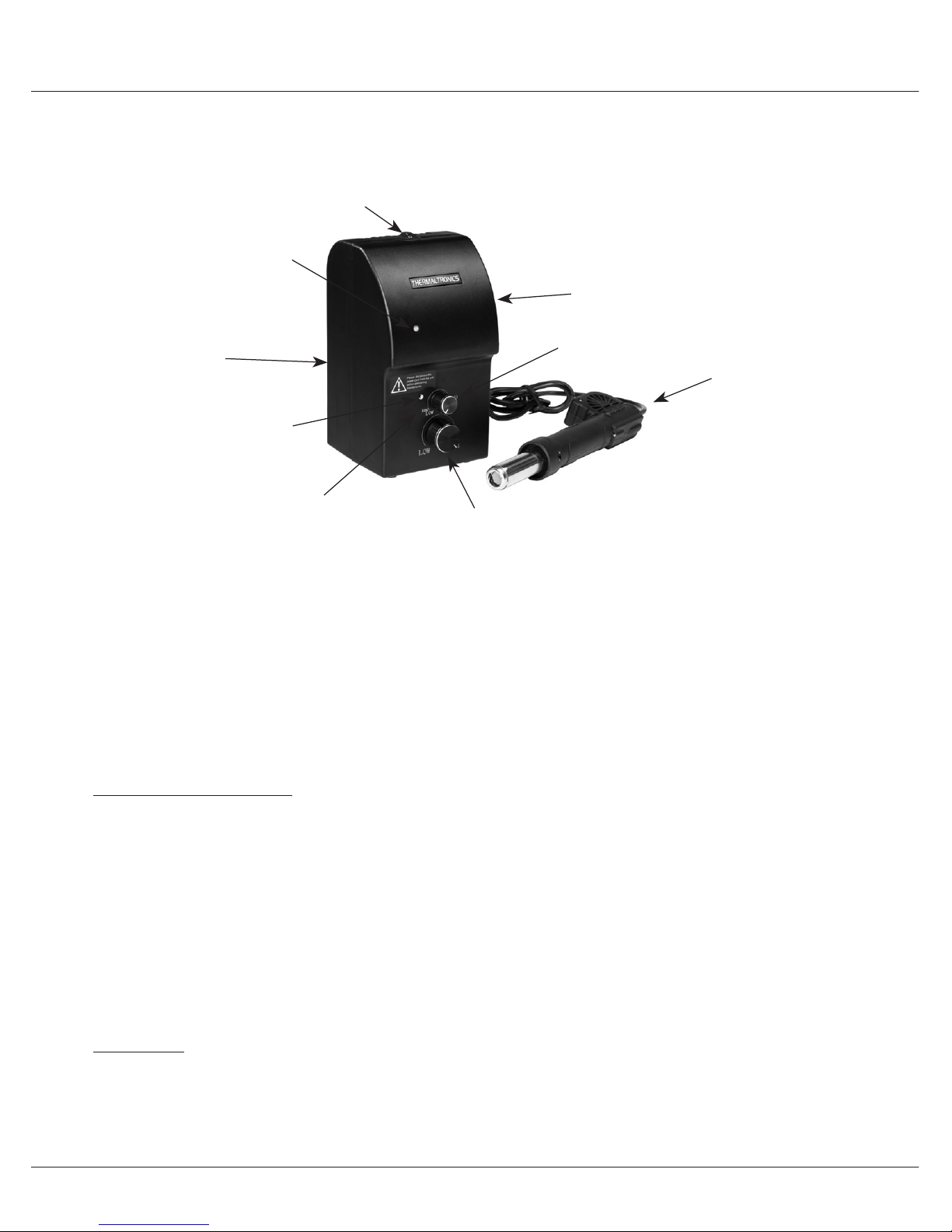
CONTROL PANEL
Temperature Knob
Air Flow Knob
Power Switch
Hot Air Gun
Handpiece Holder
ESD Paint
Power Indicator LED
Temperature
Indicator LED
Calibration

4
UNPACKING/ASSEMBLY/OPERATION
Operation - Operating Mode
Whenever the hot air gun is not placed in the holder, and the system is turned on, the unit will be in
operating mode.
Note: To prolong heating element life, always let the unit enter cool down and sleep mode
rst before turning the unit off.
Operation - Cooldown Mode
Whenever the hot air gun is placed in the holder, the system will automatically go into cooldown
mode as follows:
1. The heating element is turned off.
2. The fan will continue to blow cool air until the heating element temperature has gone down
below 100C.
3. The system goes into sleep mode.
4. Lifting the hot air gun from the holder will deactivate the cooldown mode and the system will go
back to operating mode.
Operation - Sleep Mode
Whenever the hot air gun is placed in the holder and the heating element temperature is lower than
100C.
1. The heating element is turned off.
2. The fan is turned off.
3. Lifting the hot air gun from the holder will deactivate the sleep mode.
4. In sleep mode both the power and temperature LED indicator are off.
Operation - Power off
The unit is powered down. Both the heating element and fan are off.
Note: To prolong heating element life, always turn the temperature knob fully counter
clockwise and airow knob to the midpoint after each use.
Calibrating the hot air gun
In some cases, it may be necessary to synchronize the amount of heat delivered by the hot air gun
with an external temperature sensing device. This can be achieved by the following steps:
1. Turn the temperature knob to maximum.
2. Place an external temperature sensing device near the tip of the hot air gun nozzle.
3. Wait for the temperature LED indicator to start ickering and the external temperature readout
has stabilized.
4. Unscrew the calibration screw. Insert a small screw driver into the hole and slowly turn the
calibration utility until the approximate temperature on both devices are synchronized.
Operating Cooldown Sleep Power off

5
TMT-HA200 Hot Air Tool
USER MANUAL
FREQUENTLY ASKED QUESTIONS
Q: The unit has no power.
A: Check if the unit is switched on and the power cord is plugged in. Verify that the
fuse has not blown out. Pick up the hot air gun, the unit may just be in sleep mode.
Q: The actual temperature is not increasing
A: Pick up the hot air gun, the unit may just be in sleep mode. The overheat protection
may be engaged, power off unit to cooldown and then power back on. Lastly, check if
the heating element is damaged, replace if damaged.
Q: Replacing the heating element.
Q: No air is coming out of the hot air gun
A: Check if the fan is damaged, replace if damaged.
Q: Replacing the fan.
Caution: Disconnect power before replacing the fan.
1. Remove the screws holding the hot air tool together and open the cover.
2. Disconnect and remove the heater pipe.
3. Pull back the heat shrink tube and disconnect the fan by unsoldering the power
wires. Remember the wire order (one wire is positive, one wire is negative)
4. Insert a new fan (HA-PU200).
5. Reassemble the hot air gun in the reverse order it was disassembled.
Q: Other problems
Caution: Disconnect power before replacing heater element.
1. Remove the six screws holding the hot air tool together and
open the cover.
2. Disconnect and remove the heater pipe.
3. Disconnect the heater connector, pull back the heat shrink
tube and desolder thermocouple wires.
4. Insert a new heating element (HA-HE200).
5. Reassemble the hot air gun in the reverse order it was
disassembled.
1
2
3
Fan Wires
6
ORDERING GUIDE
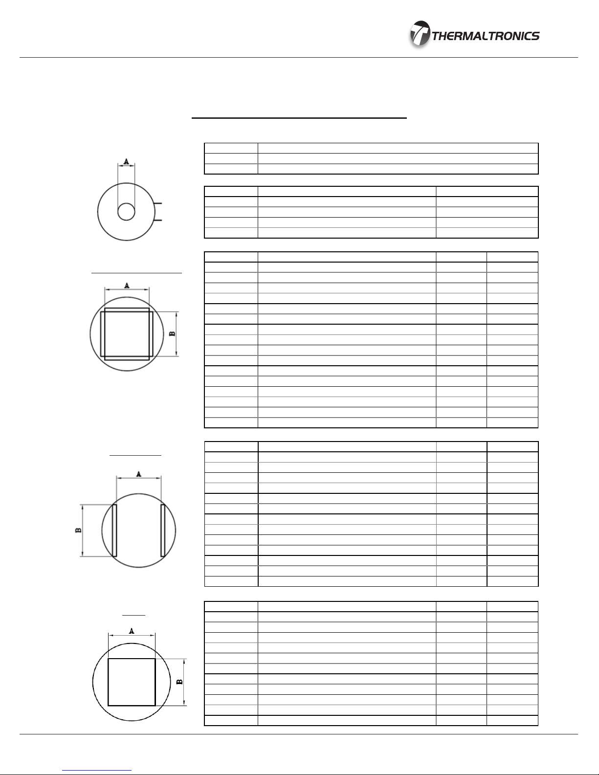
PART# DESCRIPTION A mm (in) B mm (in)
HTN-PL20 Nozzle 11.9mm x 11.9mm, PLCC-20 11.9 11.9
HTN-PL28 Nozzle 14.5mm x 14.5mm, PLCC-28 14.5 14.5
HTN-PL32 Nozzle 16.9mm x 14.3mm, PLCC-32 16.9 14.3
HTN-PL44 Nozzle 19.5mm x 19.5mm, PLCC-44 19.5 19.5
HTN-PL52 Nozzle 22.0mm x 22.0mm, PLCC-52 22.0 22.0
HTN-PL68 Nozzle 27.0mm x 27.2mm, PLCC-68 27.0 27.2
HTN-PL84 Nozzle 32.4mm x 32.4mm, PLCC-84 32.4 32.4
HTN-QF48 Nozzle 8.4mm x 8.4mm, QFP-48 8.4 8.4
HTN-QF44 Nozzle 13.4mm x 13.4mm, QFP-44 13.4 13.4
HTN-QF80 Nozzle 17.3mm x 17.3mm, QFP-52,80 17.3 17.3
HTN-QF100 Nozzle 23.4mm x 18.1mm, QFP-64,80,100 23.4 18.1
HTN-QF160 Nozzle 31.2mm x 31.2mm, QFP-120,128,144,160 31.2 31.2
HTN-BQ100 Nozzle 22.4mm x 22.4mm, BQFP-100 22.4 22.4
HTN-QF240 Nozzle 34.5mm x 34.5mm, QFP-240 34.5 34.5
HTN-BQ196 Nozzle 37.7mm x 37.7mm, BQFP-196 37.7 37.7
HTN-QF208 Nozzle 29.8mm x 29.8mm, QFP-208 29.8 29.8
PART# DESCRIPTION A mm (in)
HTN-D30 Nozzle 3.0mm 3.0
HTN-D50 Nozzle 5.0mm 5.0
HTN-D80 Nozzle 8.0mm 8.0
HTN-D100 Nozzle 10.0mm 10.0
HTN-SC16 Nozzle 6.8mm x 10.2mm, SOIC 14, 16 6.8 10.2
HTN-SL16 Nozzle 10.6mm x 10.8mm, SOL 14, 16 10.6 10.8
HTN-SL20 Nozzle 10.6mm x 13.3mm, SOL 20, 20J 10.6 13.3
HTN-SL24 Nozzle 10.6mm x 15.9mm, SOL 24, 24J 10.6 15.9
HTN-SL28 Nozzle 10.6mm x 18.4mm, SOL 28 10.6 18.4
HTN-SL44 Nozzle 16.0mm x 27.9mm, SOL 44 16.0 27.9
HTN-SJ32 Nozzle 13.5mm x 20.6mm, SOJ 32 13.5 20.6
HTN-SJ40 Nozzle 13.5mm x 25.4mm, SOJ 40 13.5 25.4
HTN-TS24 Nozzle 17.0mm x 7.1mm, TSOP 20-24 PIN 17.0 7.1
HTN-TS32 Nozzle 21.0mm x 9.1mm, TSOP 28-32 PIN 21.0 9.1
HTN-TS40 Nozzle 21.0mm x 10.8, TSOP 40 PIN 21.0 10.8
HTN-TS48 Nozzle 21.0mm x 13.3mm, TSOP 48 PIN 21.0 13.3
HTN-TS24B Nozzle 10.2mm x 18.4mm, TSOP 20-24 PIN 10.2 18.4
HTN-TS44 Nozzle 12.7mm x 19.8mm, TSOP 24-28/40-44 PIN 12.7 19.8
SO, TSOP
PLCC, QFP, BQFP
PART# DESCRIPTION
HA-HE200 Heating Element for TMT-HA200
HA-PU200 Replacement Fan for TMT-HA200
SPARE PARTS & NOZZLES
HTN-B1010 Nozzle 10.0mm x 10.0mm 10.0 10.0
HTN-B1313 Nozzle 13.0mm x 13.0mm 13.0 13.0
HTN-B1616 Nozzle 16.0mm x 16.0mm 16.0 16.0
HTN-B1919 Nozzle 19.0mm x 19.0mm 19.0 19.0
HTN-B2828 Nozzle 28.0mm x 28.0mm 28.0 28.0
HTN-B3030 Nozzle 30.0mm x 30.0mm 30.0 30.0
HTN-B3232 Nozzle 32.0mm x 32.0mm 32.0 32.0
HTN-B3636 Nozzle 36.0mm x 36.0mm 36.0 36.0
HTN-B3939 Nozzle 39.0mm x 39.0mm 39.0 39.0
HTN-B4141 Nozzle 41.0mm x 41.0mm 41.0 41.0
HTN-B4343 Nozzle 43.0mm x 43.0mm 43.0 43.0
HTN-B4545 Nozzle 45.0mm x 45.0mm 45.0 45.0
BGA
Table of contents
Other Thermaltronics Power Tools manuals


