Thermia EM330 User manual


Thermia AB is not liable or bound by warranty if these
instructions are not adhered to during installation or service.
The English language is used for the original instructions.
Other languages are a translation of the original instructions.
(Directive 2006/42/EC)
© Copyright Thermia AB

Table of Contents
1 Energy management ........................................ 2
1.1 Symbols in documents .................................... 2
1.2 General safety precautions ................................. 3
1.3 Current limiter/meter .................................... 3
1.4 Delivery content ....................................... 3
1.5 Electrical installation ..................................... 4
1.6 Communication setup (Modbus) .............................. 5
2Configuration of the heat pump control system ....................... 6
2.1 Settings in Genesis control system ............................. 6
1Energy management
1.1 Symbols in documents
The instructions contain different warning symbols, which, together with text, indicate to the user that there
are risks involved with actions to be taken.
The symbols are displayed to the left of the text and three different symbols are used to indicate the degree of
danger:
Danger Indicates an immediate danger that leads to
fatal or serious injury if necessary measures
are not taken.
Warning Risk of personal injury!
Indicates a possible danger that can lead to fa-
tal or serious injury if necessary measures are
not taken.
Caution Risk of installation damage.
Indicates a possible hazard that can lead to
item damage if necessary measures are not
taken.
A fourth symbol is used to give practical information or tips on how to perform a procedure.
Installation Guide Current limiter/meter EM330
ACCLM1IG0102 Thermia AB
2
N
Information regarding making the handling of
the installation easier or a possible operation-
al technical disadvantage.
1.2 General safety precautions
Caution The installation must be carried out by quali-
fied installation engineers and the installation
must follow the applicable local rules and reg-
ulations as well as these installation instruc-
tions.
Warning Live parts. Heart attack, burns and other inju-
ries. Disconnect the power supply and load
before installing the unit. Protect terminals
with covers.
1.3 Current limiter/meter
This equipment can monitor the total power consumption of a house, or specific electrical installation, to pre-
vent the fuses from blowing, by limiting the maximum power from the external auxiliary heater.
It may also be used for measuring electrical power load/consumption depending on where in the electrical sys-
tem it is installed.
1.4 Delivery content
The delivered equipment needed to set up the Current limiter kit 203161, is listed in the table below:
Enegy meter kit 203161
Energy meter EM330, 342594 1 pc.
Current transformer 500/5A, 342595 3 pc.
Fuse C10A 3P, 086L5679 1 pc.
Documentation 1 pc.
Installation Guide Current limiter/meter EM330
Thermia AB ACCLM1IG0102 3
GB .

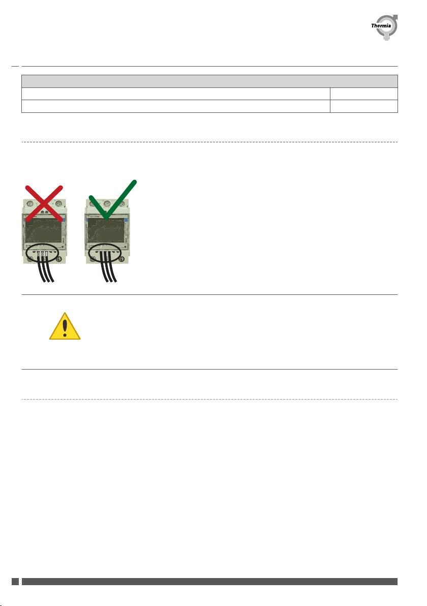
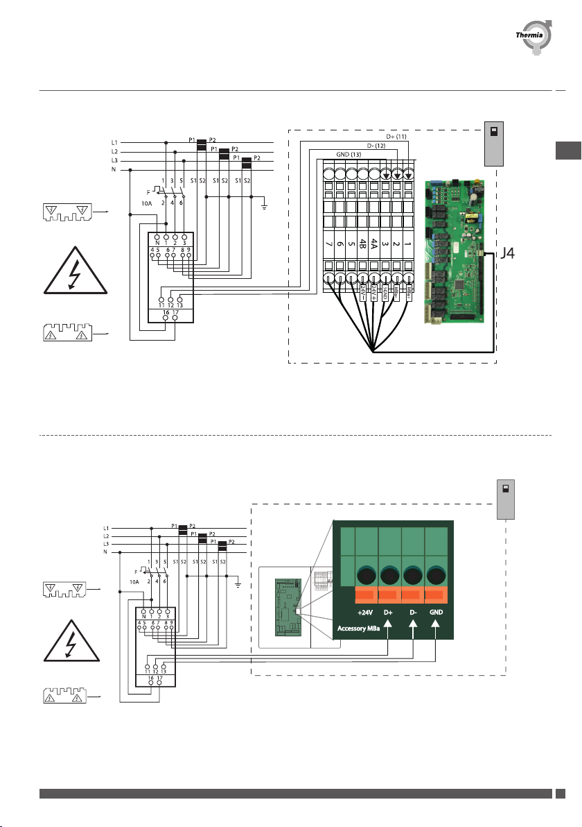
1.5 Electrical installation
Install the Current limiter in the main feed of the house or where you want to manage the power consumption
and connect according to the below instruction.
Caution Before connecting any input/output wire, the
protection cover must be correctly installed.
The metallic part of the wire or ferrule must be
completely inserted into the terminal.
1.5.1 Connection for Mega 2018 or older
Please refer to your heat pumps documentation to localize Modbus Accessory A, B and GND.
Installation Guide Current limiter/meter EM330
ACCLM1IG0102 Thermia AB
4

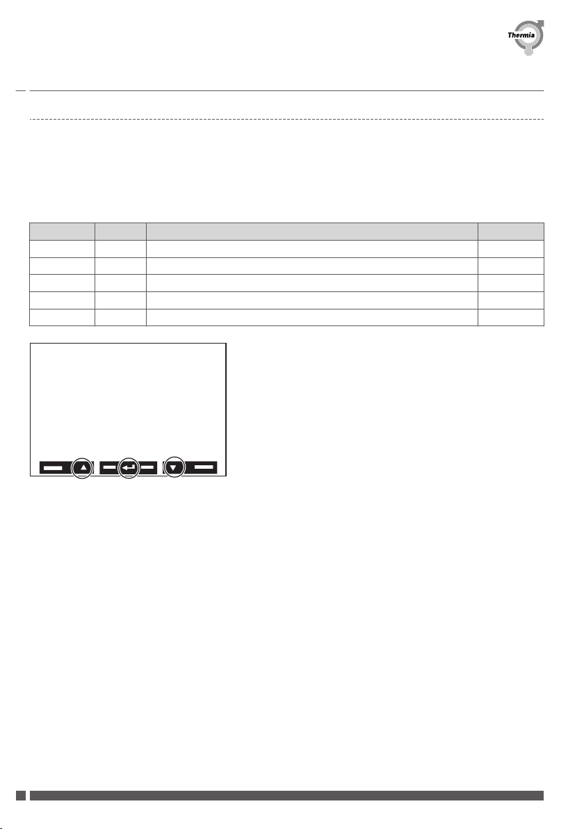
1.5.2 Connections for Mega 2019 and onwards
(11) (12) (13)
1.6 Communication setup (Modbus)
To enable communication (Modbus) between the heat pump and the Current limiter/meter, the following set-
tings must be made in the Current limiter/meter:
Push and hold the middle touch screen button until "P1" appears, hold until the values are no longer flashing,
then use the arrows to navigate to the pages listed in the table below and set values accordingly:
Page Code Description Value
CtrAtio P4 Current transformer ratio 100
AdrESS P14 Modbus address 80
bAUd P15 Baud rate 19.2
PArITY P16 Parity Even
End P18 Return to initial measurement page -
Installation Guide Current limiter/meter EM330
Thermia AB ACCLM1IG0102 5
GB .

When the configuration is complete go to "P18 End" and keep the button in the middle pressed >1s to return
to the operating data page.
2 Configuration of the heat pump control system
2.1 Settings in Genesis control system
11:20
20 ˚C
1. Start screen, the screen which appears when
the system is up and running.
Installation Guide Current limiter/meter EM330
ACCLM1IG0102 Thermia AB
6

From Genesis software 10.0
1. Press on the Start screen to open the Menu
screen.
2. Press
3. Enter the code for installer access: 60,70,80.
4. Confirm settings by pressing and .
5. Press Settings .
6. Press Installation
7. Find Current limiter, enable. Confirm with
8. Press . Press Operating mode, and then restart
the unit. (Heat pump must be set to off, and stopped.)
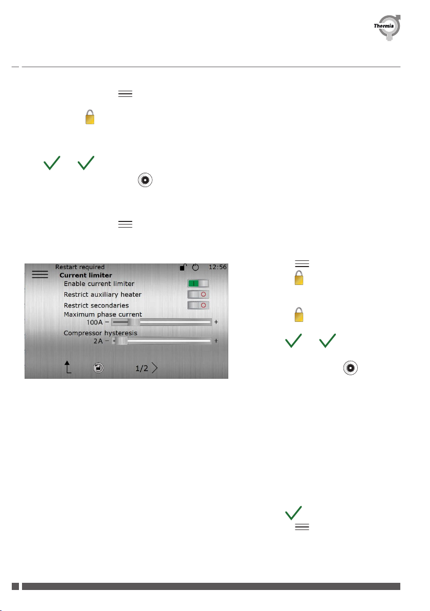
1. Press
2. Press
3. Enter the code for installer access: 60,70,80.
4. Press
5. Confirm settings by pressing and
Press Settings
Find Current limiter.
6. Enable Current limiter.
7. Enable if the heat pump should restrict the
auxiliary heater and/or secondary heat
pumps, if primary and secondary is activa-
ted.
8. Maximum phase current factory setting is
500 A.
9. Recommended settings: Set the slider just
below the value of the fuse to be protected.
10. Confirm settings by pressing .
11. Press and select Operating mode and
(normally) Auto.
When the maximum phase current is exceeded, the immersion heater will step down first, then the compressor
(if available). After being limited the compressor/immersion heater will resume normal operation once the cur-
rent is lower then the maximum phase current minus the hysteresis offset.
Installation Guide Current limiter/meter EM330
Thermia AB ACCLM1IG0102 7
GB .

Inhaltsverzeichnis
1 Energiemanagement ........................................ 8
1.1 Symbole im Dokument ................................... 8
1.2 Allgemeine Sicherheitsvorschriften ............................ 9
1.3 Strombegrenzer/Stromzähler ................................ 9
1.4 Lieferumfang ......................................... 9
1.5 Elektroinstallation ...................................... 10
1.6 Einrichtung der Kommunikation (Modbus) ........................ 12
2 Konfiguration des Steuersystems der Wärmepumpe .................... 13
2.1 Einstellungen des Genesis-Steuersystems ......................... 13
1 Energiemanagement
1.1 Symbole im Dokument
Die Anweisung enthält auch verschiedene Warnsymbole, die den Leser zusammen mit einem Text auf Risiken
und auszuführende Maßnahmen hinweisen.
Die Symbole befinden sich links vom Text; und es gibt drei Symbole, die bei unterschiedlich starken Gefahren
verwendet werden:
Gefahr Machen auf eine unmittelbare Gefahr auf-
merksam, die zu lebensgefährlichen oder
schwerwiegenden Schäden führt, wenn not-
wendige Maßnahmen nicht ergriffen werden.
Warnung Verletzungsrisiko!
Machen auf eine mögliche Gefahr aufmerk-
sam, die zu lebensgefährlichen oder schwer-
wiegenden Schäden führen kann, wenn not-
wendige Maßnahmen nicht ergriffen werden.
Achtung Gefahr für einen Schaden an der Anlage.
Informiert über eine mögliche Gefahr, die zu
Sachschäden führen kann, wenn notwendige
Maßnahmen nicht ergriffen werden.
Installationshandbuch Current limiter/meter EM330
ACCLM1IG0103 Thermia AB
8
Ein viertes Symbol wird verwendet, um praktische Informationen oder Tipps zu geben, wie eine Aktion ausge-
führt werden sollte.
N
Informationen zur Vereinfachung der Bedie-
nung der Anlage oder einem möglichen be-
triebstechnischen Nachteil.
1.2 Allgemeine Sicherheitsvorschriften
Achtung Die Installation muss von qualifizierten Instal-
lationstechnikern durchgeführt werden, wo-
bei alle anwendbaren örtlich geltenden Vor-
schriften und Bestimmungen sowie diese In-
stallationsanweisung befolgt werden müssen.
Warnung Teile stehen unter Spannung. Lebensgefahr
durch Stromschlag, Gefahr von Verbrennun-
gen oder sonstigen Verletzungen. Trennen Sie
die Stromversorgung, bevor Sie die Einheit
montieren. Schützen Sie die Anschlussklem-
men mit Abdeckungen.
1.3 Strombegrenzer/Stromzähler
Dieses Gerät kann den Gesamtstromverbrauch eines Gebäudes oder einer bestimmten Elektroinstallation über-
wachen; durch Begrenzung der maximalen Leistung einer extern Zusatzheizstufe wird verhindert, dass die
Sicherungen durchbrennen.
Es kann auch als Messgerät für die Stromlast/den Stromverbrauch verwendet werden, je nachdem wo es in der
elektrischen Anlage montiert wird.
1.4 Lieferumfang
Der für die Montage des Strombegrenzersets 203161 erforderliche Lieferumfang ist in der nachfolgenden Ta-
belle aufgeführt:
Energiezählersatz 203161
Energiezähler EM330, 342594 1 Stk.
Stromwandler 500/5 A, 342595 3 Stk.
Installationshandbuch Current limiter/meter EM330
Thermia AB ACCLM1IG0103 9
DE .
Energiezählersatz 203161
Sicherung C10 A 3P, 086L5679 1 Stk.
Dokumentation 1 Stk.
1.5 Elektroinstallation
Montieren Sie den Strombegrenzer an der Hauptstromversorgung des Gebäudes oder dort, wo Sie den Strom-
verbrauch kontrollieren wollen, und schließen Sie ihn gemäß den nachfolgenden Anweisungen an.
Achtung Vor dem Anschließen von Ein-/Ausgangska-
beln, muss die Schutzabdeckung ordnungsge-
mäß montiert sein. Der Metallteil des Kabels
oder der Quetschhülse muss vollständig in die
Anschlussklemmleiste eingesteckt sein.
1.5.1 Anschluss für Mega 2018 oder älter
Installationshandbuch Current limiter/meter EM330
ACCLM1IG0103 Thermia AB
10
Zur Lokalisierung des Modbus-Zubehörs A, B und Erdung (GND) lesen Sie bitte in Ihrem Wärmepumpen-
Handbuch nach.
1.5.2 Anschlüsse ab Mega 2019
(11) (12) (13)
Installationshandbuch Current limiter/meter EM330
Thermia AB ACCLM1IG0103 11
DE .
1.6 Einrichtung der Kommunikation (Modbus)
Folgende Einstellungen müssen am Strombegrenzer/-zähler vorgenommen werden, um die Kommunikation
(Modbus) zwischen der Wärmepumpe und dem Strombegrenzer/-zähler zu aktivieren:
Drücken und halten Sie die mittlere Touchscreen-Taste solange gedrückt, bis „P1" erscheint und die Werte
nicht mehr blinken; verwenden Sie danach die Pfeile, um zu den in der nachfolgenden Tabelle genannten Sei-
ten zu gelangen und die Werte entsprechend einzustellen:
Seite Code Beschreibung Wert
CtrAtio P4 Stromwandlerverhältnis 100
AdrESS P14 Modbus-Adresse 80
bAUd P15 Baudrate 19,2
PArITY P16 Parität Gerade
End P18 Zur ursprünglichen Messseite zurückkehren. -
Wenn die Konfiguration abgeschlossen ist, gehen Sie zu „P18 End“ und halten Sie die Taste in der Mitte länger
als eine Sekunde lang gedrückt, um zur Betriebsdatenseite zurückzukehren.
Installationshandbuch Current limiter/meter EM330
ACCLM1IG0103 Thermia AB
12

2 Konfiguration des Steuersystems der Wärmepumpe
2.1 Einstellungen des Genesis-Steuersystems
11:20
20 ˚C
1. Startbildschirm. Dieser Bildschirm erscheint,
wenn das System betriebsbereit ist und läuft.
Installationshandbuch Current limiter/meter EM330
Thermia AB ACCLM1IG0103 13
DE .
Ab Genesis-Software 10.0
1. Drücken Sie die Taste auf dem Startbildschirm,
um das Menüfenster zu öffnen.
2. Drücken Sie
3. Geben Sie den Zugangscode für den Monteur ein:
60,70,80.
4. Bestätigen Sie die Einstellungen durch Drücken von
und .
5. Drücken Sie Einstellungen .
6. Drücken Sie Installation.
7. Suchen Sie den Strombegrenzer, aktivieren Sie ihn.
Bestätigen Sie Ihre Auswahl mit
8. Drücken Sie die Taste . Drücken Sie Betriebsart
und starten Sie das Gerät erneut. (Die Wärmepumpe
muss ausgeschaltet und gestoppt sein.)
1. Drücken Sie
2. Drücken Sie
3. Geben Sie den Zugangscode für den Mon-
teur ein: 60,70,80.
4. Drücken Sie
5. Bestätigen Sie die Einstellungen durch Drü-
cken von und
Drücken Sie Einstellungen
Suchen Sie den Strombegrenzer.
6. Aktivieren Sie den Strombegrenzer.
7. Aktivieren, wenn die Wärmepumpe die Zu-
satzheizung und/oder sekundäre Wärme-
pumpen begrenzen soll, wenn die Optio-
nen primär und sekundär aktiviert sind.
8. Die Werkseinstellung für maximale Strom-
aufnahme (pro Phase) beträgt 500 A.
9. Empfohlene Einstellungen: Stellen Sie den
Schieber direkt unter den Wert der zu
schützenden Sicherung.
10. Bestätigen Sie die Einstellungen durch Drü-
cken von .
11. Drücken Sie und wählen Sie Betriebs-
art und (normalerweise) Auto.
Installationshandbuch Current limiter/meter EM330
ACCLM1IG0103 Thermia AB
14

Bei Überschreitung des maximalen Phasenstroms wird zuerst die Zusatzheizung und dann der Kompressor
(falls vorhanden) heruntergefahren. Nach der Begrenzung nimmt der Kompressor/die Zusatzheizung den Nor-
malbetrieb wieder auf, sobald der Strom niedriger ist als der maximale Phasenstrom abzüglich des Hysterese-
offsets.
Installationshandbuch Current limiter/meter EM330
Thermia AB ACCLM1IG0103 15
DE .
Innehållsförteckning
1 Energihantering ........................................... 16
1.1 Symboler i dokument .................................... 16
1.2 Allmänna säkerhetsföreskrifter ............................... 17
1.3 Strömbegränsare/-mätare .................................. 17
1.4 Innehåll i leveransen ..................................... 17
1.5 Elinstallation ......................................... 18
1.6 Kommunikationsinställning (Modbus) ........................... 19
2 Konfigurera styrsystemet för värmepumpen ......................... 20
2.1 Inställningar i Genesis-styrsystemet ............................ 20
1 Energihantering
1.1 Symboler i dokument
Anvisningen innehåller olika varningssymboler som tillsammans med text uppmärksammar läsaren på att det
finns risker med åtgärder som ska utföras.
Symbolerna visas till vänster om texten och det finns tre symboler som används vid olika grader av faror:
Fara Uppmärksammar på en omedelbar fara som
leder till livsfarliga eller allvarliga skador om
inte nödvändiga åtgärder vidtas.
Varning Risk för personskador!
Uppmärksammar på en möjlig fara som kan
leda till livsfarliga eller allvarliga skador om
inte nödvändiga åtgärder vidtas.
Försiktighet Risk för skada på anläggningen.
Informerar om en möjlig fara som kan leda till
materiella skador om inte nödvändiga åtgär-
der vidtas.
En fjärde symbol används för att ge praktisk information eller tips om hur ett moment bör utföras.
Installationsanvisning Current limiter/meter EM330
ACCLM1IG0107 Thermia AB
16

N
Information om hur hanteringen av anlägg-
ningen kan underlättas eller om en möjlig
driftteknisk nackdel.
1.2 Allmänna säkerhetsföreskrifter
Försiktighet Installationen ska utföras av en behörig instal-
latör, som måste följa gällande lokala regler
och förordningar samt den här installationsan-
visningen.
Varning Strömförande delar. Hjärtattack, brännskador
och andra skador. Koppla från strömförsörj-
ningen och belastningen innan enheten in-
stalleras. Täck över kopplingsplintarna.
1.3 Strömbegränsare/-mätare
Denna utrustning kan övervaka den totala effektförbrukningen för ett hus eller en viss elinstallation och kan
därmed förhindra att säkringarna går genom att begränsa den maximala effekten från den externa eltillsatsen.
Den kan även användas för att mäta elektrisk belastning/förbrukning beroende på var i elsystemet den installe-
ras.
1.4 Innehåll i leveransen
Medföljande utrustning som behövs för att installera strömbegränsarsatsen 203161 framgår av nedanstående
tabell:
Energimätarsats 203161
Energimätare EM330, 342594 1 st.
Strömtransformator 500/5 A, 342595 3 st.
Säkring C10A 3P, 086L5679 1 st.
Dokumentation 1 st.
Installationsanvisning Current limiter/meter EM330
Thermia AB ACCLM1IG0107 17
SE .

1.5 Elinstallation
Installera strömbegränsaren vid husets primära ingående strömmatning eller på den plats där du vill övervaka
effektförbrukningen och anslut den enligt instruktionerna nedan.
Försiktighet Innan några in-/utgående ledningar ansluts
måste skyddslocket installeras korrekt. Led-
ningens eller hylsans metalldel måste stickas
in helt i plinten.
1.5.1 Anslutning för Mega 2018 eller tidigare
Information om hur du hittar anslutningspunkt A, B och GND för Modbus-tillbehöret finns i dokumenta-
tionen för värmepumpen.
Installationsanvisning Current limiter/meter EM330
ACCLM1IG0107 Thermia AB
18
Table of contents
Languages:


