STI Magnetrol Thermatel TA1 User manual

DESCRIPTION
The Thermatel Mass Flow Transmitter Model TA1 provides
high performance measurement of the mass flow of air and
other gases. Using a heated sensor, the mass flow is deter-
mined by accurately measuring the temperature difference
between the heated sensor and the reference sensor. Heat
transfer is due to the mass of the gas flowing past the sen-
sor providing a measurement of the mass flow rate.
The advanced microprocessor provides accurate tempera-
ture compensation as the process temperature changes.
Each instrument is factory calibrated in a NIST flow standard
to provide highest level of accuracy. The electronics permit
the user to configure the instrument for the pipe or duct size,
zero and span, units of measurement, alarms, and other user
specific requirements.
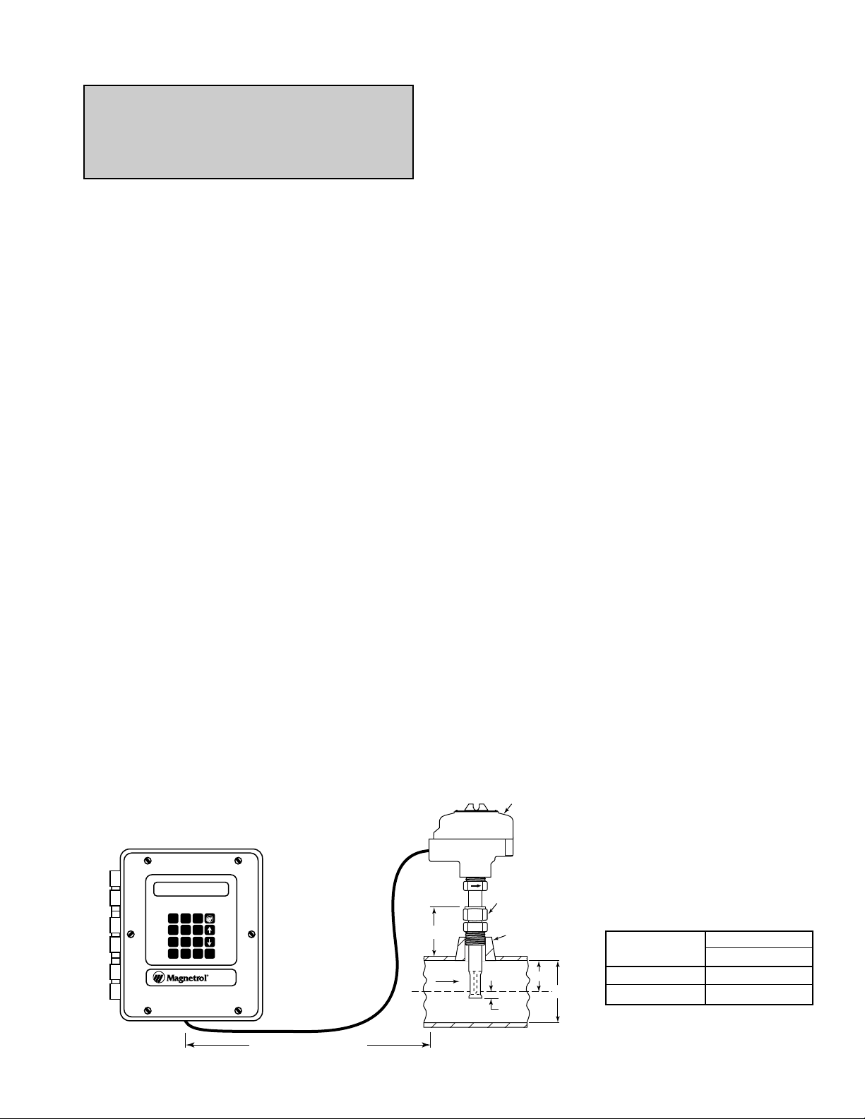
The instrument provides two 4–20 mA output signals; one for
flow measurement, and one for temperature. Each 4–20 sig-
nal can be configured from the instrument.
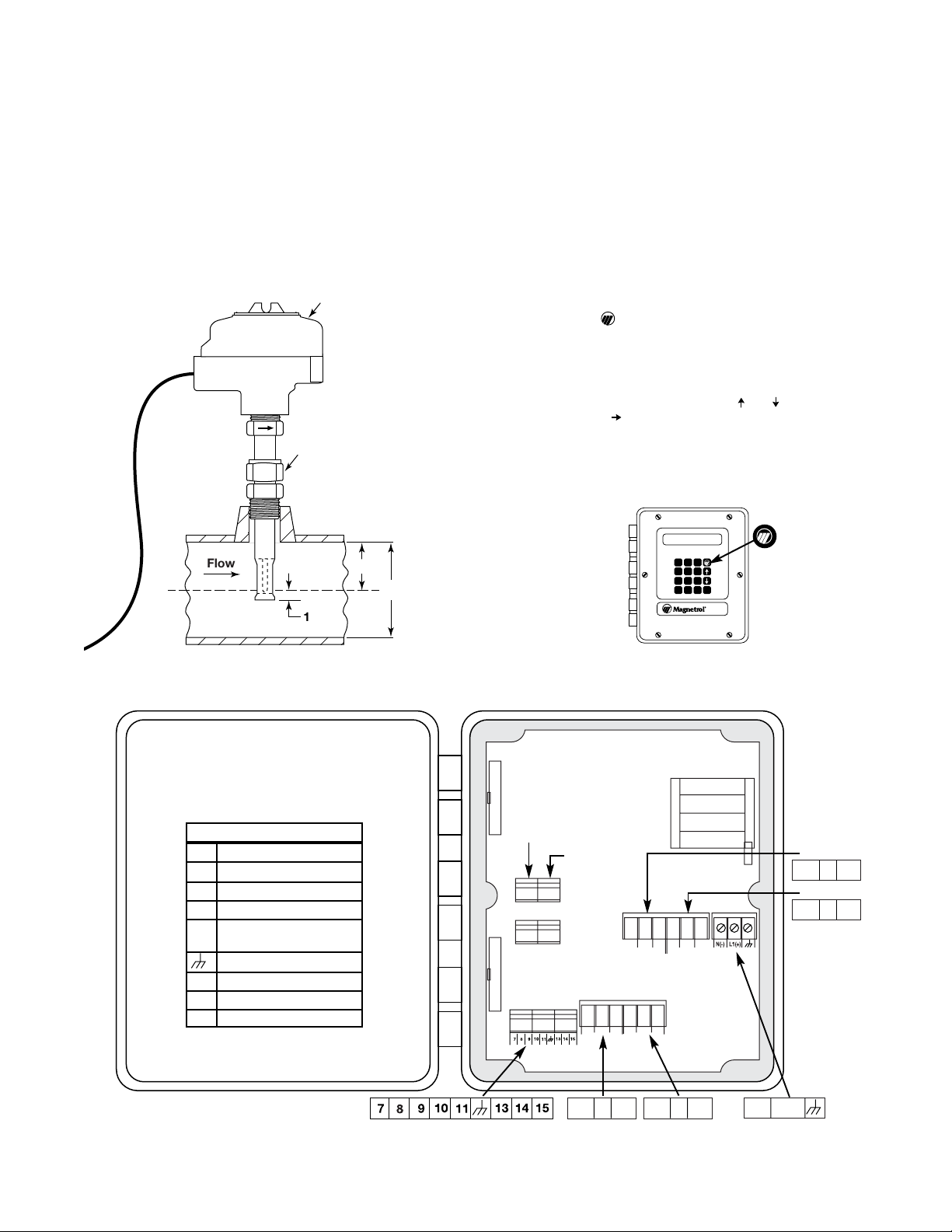
PRINCIPLE OF OPERATION
The flow element of the TA1 Mass Flow Transmitter
utilizes a heater and two resistant temperature detectors
(RTDs). The heater and the active RTD are contained in one
sensor; the second sensor contains the reference RTD and a
mass balancing element.
The reference RTD measures the temperature of the process
where the flow element is installed. A constant power is pro-
vided to the heated sensor. The active RTD measures the
temperature of the heated sensor. The electronics measures
the temperature difference between the active and reference
RTD.
There is an inherent non-linear relationship between the tem-
perature difference and the mass flow rate. The micro-
processor-based electronics convert the temperature differ-
ence signal to provide a linear measurement of the mass flow
rate. The electronics also provide advanced temperature
compensation which automatically adjusts the flow meas-
urements for changes in process temperature.
The 4–20 mA output signal can be adjusted to provide max-
imum resolution of flow measurement over the desired range
of the instrument. A separate 4–20 mA signal provides an
output signal of the process temperature. Both 4–20 mA sig-
nals can be wired for either active or passive operation. Refer
to wiring section, pages 4 and 5.
Optional relays provide low or high flow alarm indication and
can be used for diagnostics.
UNPACKING
Unpack the instrument carefully, making sure all components
have been removed from the packing material. Inspect all
components for damage, and report any concealed damage
to the carrier within 24 hours. Check the contents of the car-
ton, making sure it agrees with the packing slip and the pur-
chase order. Verify that the model number imprinted on the
nameplate matches the number on the packing slip and the
purchase order. Report any discrepancies to the factory.
Check and record the serial number for future reference
when ordering parts.
Thermatel®
Mass Flow Transmitter
Model TA1
Instruction Manual and Parts List
TABLE OF CONTENTS PAGE
Description . . . . . . . . . . . . . . . . . . . . . . . . . . . . . . . . . . . . .1
Principle of Operation . . . . . . . . . . . . . . . . . . . . . . . . . . . . .1
Unpacking . . . . . . . . . . . . . . . . . . . . . . . . . . . . . . . . . . . . . .1
Quick Start . . . . . . . . . . . . . . . . . . . . . . . . . . . . . . . . . . . . .2
Installation . . . . . . . . . . . . . . . . . . . . . . . . . . . . . . . . . . . . . .3
Electrostatic Discharge Handling Procedure . . . . . . . . . . .4
Wiring . . . . . . . . . . . . . . . . . . . . . . . . . . . . . . . . . . . . . . . . .4
Software Configuration . . . . . . . . . . . . . . . . . . . . . . . . . . . .6
Digital Communication RS-485/Modbus Protocol . . . . . . .21
Troubleshooting . . . . . . . . . . . . . . . . . . . . . . . . . . . . . . . .22
Maintenance . . . . . . . . . . . . . . . . . . . . . . . . . . . . . . . . . . .22
Agency Approvals . . . . . . . . . . . . . . . . . . . . . . . . . . . . . . .23
Specifications . . . . . . . . . . . . . . . . . . . . . . . . . . . . . . . . . .23
Model Number . . . . . . . . . . . . . . . . . . . . . . . . . . . . . . . . .26
Replacement parts . . . . . . . . . . . . . . . . . . . . . . . . . . . . . .30
Glossary . . . . . . . . . . . . . . . . . . . . . . . . . . . . . . . . . . . . . .31
®

NO C NC NO C NC
NO C NC
Relay 3TB11 Probe connection
NO C NC
Relay 4
Relay 3 Relay 4
TB1 Power connection
TB11
TB1
Relay 1 Relay 2
N(-) L1(+)
NO C NC NO C NC
Relay 1
Passive
4–20 mA
output
Active
4–20 mA
output NO C NC
Relay 2
NO C NC
Probe Wiring Connections
7 No connection
8 Brown w/white stripe
9 Green w/white stripe
10 Blue w/white stripe
11 Orange w/white stripe
White w/orange stripe
Shield
13 White w/brown stripe
14 White w/green stripe
15 White w/blue stripe
Wiring Color Codes
78
45
12
.0
9
6
3
DEL ENT
MODEL
TA1
Figure 3
2
WIRING
Open the cover of the enclosure and locate the input power
connections, the 4–20 mA output connections, and the
relay connections as show below. Make connections
between the probe and the electronics to terminal block
TB11. Refer to Figure 2
CONFIGURATION
The instrument is configured at the factory with the applica-
tion information provided with the order. If configuration
information was not provided at the time of order, then the
information used during the calibration is utilized. To quickly
configure the instrument or change the configuration, push
the logo button ( ) located at the upper right on the key
pad (refer to Figure 3), then enter the requested information.
Simply enter the pipe or duct area in square inches and the
4 and 20 mA points for the flow and temperature readings.
The configuration software is easily followed. Simply press
ENT to enter or change a value and or (up or down
arrow) to select. If appears on the second line, enter the
number using the keypad, and press ENT.
The complete configuration may be viewed using the soft-
ware menu which begins on page 8.
;;
;;
;;
Flow
1.00
Optional compression
fitting
D
D/2
Probe wiring housing
Figure 1
Figure 2
QUICK START
PROBE INSTALLATION
Insert the probe into the pipe or duct, ensuring that the
appropriate upstream and downstream dimensions are
obtained. It is preferred to have as much straight run as pos-
sible. Refer to Magnetrol bulletin 54-131 (STI bulletin 95-165)
for additional information on probe location. It is generally
suggested that the sensor be mounted on the centerline of
the pipe. Insure that the flow arrow on the probe is posi-
tioned in the direction of the flow. Refer to Figure 1.

INSTALLATION
3
NOTE: The instrument is rated per IEC 1010 for use in
Installation Category II, Pollution Degree 2.
ELECTRONICS
The electronics are rated for use in Class I, Division 2 areas.
The enclosure is also rated NEMA 4X.
The remote electronics should be installed in an easy to
access location within 250 feet of the sensor location. The
electronics should not be installed in areas where ambient
temperature exceeds +160° F (+70° C). If ambient tempera-
tures are less than -4° F (-20° C), then the optional heater is
recommended. Provide watertight seals for all wiring
entrances in the enclosure to maintain the NEMA 4X rating.
Mount the enclosure to a wall or flat surface using the appro-
priate screws or bolts. The mounting tabs on the back of the
enclosure may be rotated to the sides or top and bottom to
facilitate mounting. Refer to Figure 15.
NOTE: A switch or circuit breaker shall be installed in close
proximity to the equipment and within easy reach of the
operator. It shall be marked as the disconnecting device for
the equipment.
PROBE
The probe enclosure is rated explosion proof for Class I,
Division 1 service. The enclosure is also rated NEMA 4X. Use
appropriate NEC section when installing the instrument.
Proper installation of the probe in the pipe or duct is essen-
tial for accurate flow measurement. Normal procedures for
installing any type of flow element should be followed. Refer
to Magnetrol bulletin 54-131 (STI bulletin 95-165) for addi-
tional information on probe location.
Arrows are etched on the sides of the probe to designate
flow direction. The instrument is calibrated with the flow in
this direction. Ensure that the flow arrows are oriented in the
direction of flow. Refer to Figure 4.
It is generally recommended that the sensor be located in
the center of the pipe. This location provides less sensitivity
to changes in flow profile. The probe’s length should be
specified to position the sensor in the desired location.
Sensors mounted through compression fittings have the
ability to field adjust the sensor to the desired location by
using the dimensions as shown in Figure 4.
Various methods of mounting the probe are available, includ-
ing compression fittings, threaded, and flanged connections.
Refer to probe model numbers.
The insertion probe can be installed through a compression
fitting. The use of a bored-through fitting for 3⁄4" outside diam-
eter tube is recommended.
Pressure ratings of the compression fitting are:
Stainless steel ferrules 1500 psig at 70° F
1375 psig at 400° F
Teflon ferrules 100 psig
NOTE: The sensor must be installed in a location where
moisture cannot drip or come in contact with the heated ele-
ment. Any contact with condensed moisture in the gas flow
will cause a false high flow indication.
FLOW BLOCKAGE
The TA1 Mass Flow Transmitter measures the velocity flow-
ing past the sensor, and then determines the flow rate by
multiplying the area by the velocity. The probe blocks a por-
tion of the pipe reducing the effective cross sectional area of
the pipe and creating a higher velocity. The TA1 compen-
sates for this error by correcting the measured flow by the
probe blockage.
NOTE: If equipment is used in a manner not specified by
manufacturer, protection provided by equipment may be
impaired.
CAUTION: The probe and electronics are calibrated
and shipped as a matched set. The model number is
indicated on both the electronics nameplate and the
probe housing nameplate; verify that they are the same.
Flow
1.00
Optional compression
fitting
3/4" or 1" NPT
recommended
D
D/2
Probe wiring housing
A
78
45
12
.0
9
6
3
DEL ENT
MODEL
TA1
250 feet maximum (76 m)
Figure 4
NOTE: Typical height when compression fitting
is used with half coupling or threadolet.
Height
Connection size A
1" NPT 3.1 (79)
3⁄4" NPT 2.6 (66)

4
Magnetrol’s electronic instruments are manufactured to the
highest quality standards. These instruments utilize electron-
ic components which may be damaged by static electricity
present in most work environments. The following steps are
recommended to reduce the risk of component failure due to
electrostatic discharge:
1. Ship and store circuit boards in anti-static bags. If an
anti-static bag is not available, wrap board in aluminum
foil. Do not place boards on foam packing materials.
2. Use a grounding wrist strap when installing and remov-
ing circuit boards. A grounded workstation is also rec-
ommended.
3. Handle printed circuit boards only by the edges. Do not
touch components or connector pins.
4. Ensure that all electrical connections are completely
made and none are partial or floating. Ground all
equipment to a good earth ground.
ELECTROSTATIC DISCHARGE (ESD) HANDLING PROCEDURE
WIRING
WIRING
There are three predrilled holes in the enclosure for connect-
ing 1⁄2" conduit. Generally, these are used as: one for input
power; one for cable to the probe; and one for communica-
tions (4–20 mA and relays).
PROBE WIRING
The probe housing contains a terminal block for ease of
wiring between the probe and the electronics. Connections
from the probe to the terminal strip are prewired at the fac-
tory. An 8-wire shielded interconnecting cable (Belden 8104)
from the probe housing to the instrument is required. Refer
to Figure 6 for wiring connections for TB11.
The layout of the main circuit board giving all user interface
points is shown in Figure 6.
GROUND CONNECTION
To prevent electromagnetic noise, the instrument must be
grounded in accordance with Article 250 of the National
Electric Code. Ground wires shall be terminated at the con-
duit connection using grounding bushings or other similar
device as discussed in NEC Article 250-72. Metal conduit
must be utilized to ensure proper ground connection.
Grounding of the electronics is accomplished with a ground
wire between the ground terminal in TB1 and the conduit
ground.
Probe housing must be grounded via protective ground
screw in the base of the housing.
TB1
TB11
Figure 6
Ground
Relay 2
Relay 2
Relay 1
JP9
JP1
Relay 1
TB6
4–20 mA
connections
active or
passive
(refer to
Figure 7 or
Figure 8)
Relay 4
Probe connections
(refer to Figure 5)
Relay 3
NO C NC
7 8 9 10 11 13 14 15 NO C NC
A B
TB16
RS-485
connection
NC
C
NO
NC
C
NO
Probe Wiring Connections
to TB11
7 No connection
8 Brown/white stripe
9 Green/white stripe
10 Blue/white stripe
11 Orange/white stripe
White/orange stripe
Shield
13 White/brown stripe
14 White/green stripe
15 White/blue stripe
Wiring Color Codes
Probe Wiring Connections
Probe Housing
1 Green/white stripe
2 White/green stripe
3 Blue/white stripe
4 White/blue stripe
5 Brown/white stripe
6 White/brown stripe
7Orange/white stripe
White/orange stripe
8 Shield
Wiring Color Codes
Figure 5
Probe Enclosure Wiring Connections
Black or Brown
8
7
6
5
4
3
2
1
5
4
3
2
1
Orange
Blue
Black
White
N (–)
L1 (+)

RELAY OUTPUT WIRING
The instrument can be supplied with up to four isolated
SPDT relays, rated at 10 amp at 120 VAC or 5 amp at
240 VAC. The relays can be configured for use as high or low
level alarm contacts. In addition, Relay 1 can be configured,
via software, to de-energize only in the event a fault condi-
tion is detected.
All relay terminals are labeled Cfor common, NC for normal-
ly closed, NO for normally open. Refer to Figure 6.
POWER CONNECTION
The instrument is factory wired to accept 24 VDC, 120 VAC,
or 240 VAC. Check the nameplate to ensure that the instru-
ment matches the desired input power.
All power wiring connections are made to terminal block
TB1. Refer to Figure 6.
NOTE: Use a minimum of 14-AWG wire for power and
ground field wires. For supply connection, use wire with a
minimum rating of +75° C as required by process conditions.
4-20 mA DC OUTPUT
Two 4–20 mA output connections are available at terminal
block TB6. These output signals are electrically isolated from
the instrument, but are not isolated with respect to each
other. Either an active or passive connection may be selected.
To obtain an active 4–20 mA output signal, the positive con-
nection for each loop is made to ACT+. The negative con-
nection is made as follows (refer to Figure 7):
Flow signal 1ACT-
Temperature signal 2ACT-
A passive 4–20 mA signal requires an external DC power
supply (maximum voltage of 32 VDC). The negative con-
nection of the power supply is connected to -PAS (refer to
Figure 8):
The positive connection is:
Flow signal +PAS1
Temperature signal +PAS2
NOTE: The active circuit shares a common positive while the
passive circuit shares a common negative. If both a flow and
temperature signal are desired using a PLC, it is recom-
mended that the flow signal be treated as an active circuit
while the temperature signal be handled as a passive circuit.
Flow signal
Temperature signal
1ACT
ACT
2ACT
Figure 7
Flow signal
Temperature signal
Power
supply
PAS1
PAS
PAS2
Figure 8
WIRING cont.
CLOSING THE COVER
After all wiring connections are complete, close and secure
the cover using the six screws.
CAUTION: Do not overtighten the securing screws. Do not
use an electrical drive. Overtightening can result in cracking
of the housing resulting in leakage into the housing.
RS–485/MODBUS OUTPUT
Modbus communication via RS-485 is available at terminal
block TB16.
The terminals are marked A and B, which correspond to sim-
ilar connections in the control room.
NOTE: Polarity among units in the loop must be observed.
The shield is connected to the terminal.
Jumper JP1 provides the terminal resistor if the instrument is
the last instrument in a daisy chain configuration. The posi-
tion of the jumper at JP1 should be set as follows (refer to
Figure 9):
RS–232 CONNECTION
The RS–232 Connection on TB7 is currently not utilized.
Jumper JP9 provides the selection of either RS–232 or
RS–485 connection. The jumper must be left in the position
indicated below.
MODBUS WIRING
Refer to Modbus section on page 21 for wiring information.
JP9
Figure 10
JP1
C
JP1
C
Continuing Position Terminating Position
Default
Figure 9
5

6
The electronics of the instrument are easy to set up and con-
figure for the user’s specific requirements. If previously
specified, the configuration menu is loaded into the instru-
ment at the factory. If not, or if the user wants to modify the
configuration settings, follow these instructions for configur-
ing the instrument. The primary structure of the software is
divided into six main groups:
All input of information is done via the keypad located on the
front of the instrument.
PASSWORD
A password protection system restricts access to portions
of the menu which affect the unit’s operation and configura-
tion. The password will be requested whenever program-
ming changes are requested.
The password may be changed to any four digit number.
This procedure is described under ADV CONFIG menu on
page 19.
CAUTION: The instrument is shipped from the factory
with the password 100. If the password is misplaced or
forgotten, please consult the factory for assistance.
OPERATOR KEYPAD
All unit configuration instructions in this manual will appear
on the instrument display. The following keys are used:
UP arrow: Scroll to the previous menu item or enter
“e” for exponential
DOWN arrow: Scroll to the next menu item or enter
negative number.
ENTER: Enter next menu level or confirm information
of the current menu item.
DELETE: To exit the current item/menu level or delete
an entry.
Numeric input of data.
Decimal point.
QuickCal mode.
When the symbol is displayed on the top line, push ENT
to program this selection, or press to proceed to the
next selection.
When the symbol is displayed on the bottom line, push
to change the selection; then push ENT to accept.
When the symbol is displayed on the bottom line, enter
the value, then push ENT to accept.
NOTE: Pressing DEL will back you out of the configuration
menu and return you to run mode.
NOTE: If a key is not pressed for 5 minutes, the display
returns to the run mode.
SOFTWARE CONFIGURATION
Measured Values View selected values
System Config First time configuration (essential pro-
gramming information)
I/O Config Configure all input/output functions
Advanced Config Additional configuration which affects
the units operation
Diagnostics Test functions
Run Mode Normal operating mode
DEL
ENT
0–9
.

7
DEFINITIONS
The following symbols and definitions are used in the soft-
ware configuration:
Calibration factor: Changes in flow profile will affect the
measurements of the TA1. Advanced users have the
ability to adjust the measurements for changes in flow
profile using a multi-function polynomial relationship in
the form of:
Corrected flow = a+bx+cx2+dx3+ex4
The default is b = 1; and a, c, d, and e = 0. To use the
correction factor, develop a relationship between the
flow measured by the TA1 and the flow measured by a
second flowmeter. Curve fit the fifth order polynomial
(above) using the output of the TA1 for X (units of SFPM)
and the output of the second flowmeter for corrected
flow. Then enter the appropriate values in the Advanced
Configuration menu, page 19.
Mass flow: Measured in various units, typically LB/Hr or
KG/Hr. An input of the cross sectional area of the pipe or
duct is required.
STP conditions: The mass flow rate is based on a given
set of Standard Temperature and Pressure (STP) condi-
tions. Magnetrol uses default of 70° F and one (1) atmos-
phere for STP conditions. The STP conditions may be
modified to match the user’s standards. If the STP con-
ditions are modified, the TA1 will recalculate the flow
rates at the specified STP conditions.
The advanced configuration menu permits the user to
enter any desired temperature and cycle between selec-
tion of one (1) bar or one (1) atmosphere of pressure.
Totalized flow: Provides a measurement of the total flow
in units specified.
Velocity: Measured in SF/M (standard feet per minute) or
NM/M (normal meters per minute). This is the mass
velocity directly measured by the instrument referenced
to the appropriate standard conditions.
Volume flow: Measured in various units, typically SCFM
(standard cubic feet per minute) or NCMH (normal cubic
meters per hour), referenced to standard conditions. An
input of the cross sectional area of the pipe or duct is
required to obtain this value.
TAG LINE
Initially the tag line on the display reads “Magnetrol Int’l”.
This can be changed from the advanced configuration sec-
tion of the software.
The cursor appears in the left position. To change the posi-
tion at that location, use the or arrow keys. Pressing the
key will start scrolling the characters; pressing the a
second time causes a faster scroll. To stop scrolling, press
any key. To move to the next position, press the ENT key; to
return to the previous position, press the DEL key.
Pressing the ENT key moves the cursor to the right. When it
reaches the rightmost position, pressing the ENT key one
additional time exits and saves changes (password protected).
Pressing the DEL key moves the cursor to the left. When it
reaches the leftmost position, pressing the DEL key exits the
menu and restores the previous tag line.
SOFTWARE CONFIGURATION cont.

8
4 mA point
20 mA point
Previous menu
SOFTWARE CONFIGURATION cont.
GENERAL PROGRAMMING MENU
Following is the general menu structure used in the Mass Flow Transmitter. Use the UP or DOWN arrow key ( )to scroll
through any portion of the menu, press ENT key to make a selection, and press DEL to backup.
QUICK START
Area (enter area in
square inches)
Velocity On main display
Off main display
Flow On main display
Off main display
Mass On main display
Off main display
Temperature On main display
Off main display
Loop flow On main display
Off main display
Loop temperature On main display
Off main display
Relays 1234 On main display
Off main display
Total On main display
Off main display
Previous menu
4–20 mA (flow)
4–20 mA
(temperature)
4 mA point
20 mA point
Previous menu
Previous menu
Enter password
RUN MODE
MEASURED VALUES

9
SOFTWARE CONFIGURATION cont.
Flow units
RUN MODE
Mass units Pounds/hour
Pounds/minute
Kilograms/hour
Kilograms/minute
Temperature units Fahrenheit
Rankine
Celsius
Kelvin
Diameter units Inches
Feet
Meters
Millimeters
Area units Square inches
Square feet
Meters squared
Millimeters squared
Flow area
Previous menu
Diameter Enter value
Area
Previous Menu
Velocity units Standard feet/minute
Normal meters/minute
SYSTEM CONFIG
Select relay Fault relay #1 only Enable/disable
Controlled by
Alarm set point
Reset point
Fault mode
Previous menu
Relay action
Set point delay
(0–255 seconds)
Reset delay
(0–255 seconds)
Enable/disable
Relay settings
Velocity
Flow
Mass
Temperature
Totalizer
De-energize < set point
De-energize > set point
De-energize on fault
Hold on fault
GENERAL PROGRAMMING MENU cont.
Enter value
I/O CONFIGURATION
SCFM
SCFS
NCM/hour
NCM/minute
NL/hour

10
Enable/disableTotalizer
Totalizer units
Previous menu
Reset
Controlled by
Address (1–247)
Baud rate
Comm port setup
Standard cubic feet (SCF)
Normal cubic meters (NCM)
Normal liters (NL)
Pounds
Kilograms
Tons
1200
2400
4800
9600
Parity Odd
Even
None
Previous menu
Press ENT to reset
Flow
Mass
Enable/disable
4 mA point
20 mA point
Previous menu
Controlled by
4–20 mA (flow)
setting
Velocity
Flow
Mass
Fault mode 22 mA
3.5 mA
Hold
Enable/disable
20 mA point
Previous menu
4 mA point
4–20 mA (tempera-
ture) setting
Fault mode 22 mA
3.5 mA
Hold
SOFTWARE CONFIGURATION cont.
GENERAL PROGRAMMING MENU cont.

11
Enter tag line Change tag
Magnetrol Int’l
SOFTWARE CONFIGURATION cont.
RUN MODE
GENERAL PROGRAMMING MENU cont.
Change password
Adjust loop flow
Calibration factor
STP conditions
Previous menu
Enter old password
Enter new password
Re-enter new password
Previous menu
A = 0
B = 1
C = 0
D = 0
E = 0
Previous menu
Calibration
coefficients1*
A1 = XXX
B1 = XXX
C1 = XXX
D1 = XXX
E1 = XXX
Temperature 1 = XXX
Previous menu
Calibration
coefficients2*
A2 = XXX
B2 = XXX
C2 = XXX
D2 = XXX
E2 = XXX
Temperature 1 = XXX
Previous menu
Temperature Enter value
Probe Type TXR Probe
TXT Probe
Flow Body
4 mA offset 20 mA offset
Adjust loop
temperature
4 mA offset 20 mA offset
1 atmosphere
1 bar
Pressure
Previous menu
Temp Comp Coef*
Gas density*
*These values are “Read Only;” contact Magnetrol to change data.
ADVANCED CONFIG
Damping (1–60)
Temp coeff A
Temp coeff B
Previous menu

12
MAIN MENU
The main menu is used to access the various subroutines. From the Run mode, press or to enter the Main Menu. The
chart at right defines the various selections available from the Main Menu
Main Menu
Display Option Action if ENT is pressed
Measured Values
to select Press ENT to select or or to continue. Enter Measured Values menu
System Config
to select Press ENT to select or or to continue. Enter System Configuration menu
I/O Config
to select Press ENT to select or or to continue. Enter I/O Configuration menu
ADV Config
to select Press ENT to select or or to continue. Enter Advanced Configuration menu
Diagnostics
to select Press ENT to select or or to continue. Enter Diagnostics menu
Run mode
to select Press ENT to select or or to continue. Enter Run mode
SOFTWARE CONFIGURATION cont.
GENERAL PROGRAMMING MENU cont.
Test relays
Previous menu
View version
Test 4–20 loop 1
Select relay 1–4 Energize
De-energize
Enter loop value
4–20
Test 4–20 loop 2 Enter loop value
4–20
Sensor signal
DIAGNOSTICS MENU

13
SOFTWARE CONFIGURATION cont.
QUICK START
Quick Start
Display Option Action if ENT Option Action if ENT
is Pressed is Pressed
Enter password Enter password Proceed with
Quick Start
Area Press ENT to change area or Area Enter area of pipe or duct in
xxx in ^2 to continue to next selection. xxxx in^2 square inches and press ENT.
4–20 mA (flow) Press ENT to select or or 4 mA point Press ENT to select or or Enter flow value in
to select to continue to next selection. XXX SCFM to continue to next selection. SCFM representing
4 mA; press ENT.
20 mA point Press ENT to select or or Enter flow value in
XXXXX SCFM to continue to next selection. SCFM representing
20 mA; press ENT.
Previous menu Press ENT to return to main
to select menu or or to return to
4–20 mA (flow) setting.
4–20 mA (temp) Press ENT to select or or 4 mA point Press ENT to select or or Enter temperature in
to select to continue to next election. XX F to continue to next selection. degrees F representing
4 mA; press ENT.
20 mA point Press ENT to select or or Enter temperature in
XXX F to continue to next selection. degrees F representing
20 mA; press ENT.
Previous menu Press ENT to return to main
to select menu or or to return to
4–20 mA (temperature) setting.
Previous menu Press ENT to return to run
mode or or to return to
area setup.

14
SOFTWARE CONFIGURATION cont.
Measured Values
Display Option Action if ENT is Pressed Comments
Velocity Press ENT to select or or Press or to cycle between “ON Main
xxxxx units to continue to next selection. Display” and “OFF Main Display”;
press ENT to select.
Flow Press ENT to select or or Press or to cycle between “ON Main
xxxxx units to continue to next selection. Display” and “OFF Main Display”;
press ENT to select.
Mass Press ENT to select or or Press or to cycle between “ON Main Required input of Area in
xxxxx units to continue to next selection. Display” and “OFF Main Display”; System Config to calculate.
press ENT to select.
Temp Press ENT to select or or Press or to cycle between “ON Main
xxxxx units to continue to next selection. Display” and “OFF Main Display”;
press ENT o select.
Loop Flow Press ENT to select or or Press or to cycle between “ON Main
xxxxx mA to continue to next selection. Display” and “OFF Main Display”;
press ENT to select.
Loop Temp Press ENT to select or or Press or to cycle between “ON Main
xxxxx mA to continue to next selection. Display” and “OFF Main Display”;
press ENT to select.
Relays 1234 Press ENT to select or or Press or to cycle between “ON Main Displays Relay status; * signifies
= ENRG to continue to next selection. Display” and “OFF Main Display”; that the indicated relay is
press ENT to select. energized.
Total Press ENT to select or or Press or to cycle between “ON Main Totalizer must be enabled in
xxxxx units to continue to next selection. Display” and “OFF Main Display”; I/O Configuration menu for this
press ENT to select. section to be displayed.
Previous menu Press ENT to return to main Return to previous menu or
to select menu or or to continue cycle through measured values.
to selection.
MEASURED VALUES
The measured values menu is used to display current measured values and to determine which units will be shown on the
display during run mode.
Access the Measured Values menu by pressing or from the run menu; press ENT. The display then cycles through the
various values and permits these values to be displayed during run mode.
To display an item during the RUN mode, press ENT when that selection is displayed; then press or until “ON Main
Display” is indicated on the second line. Then push ENT.
Pressing moves up and down the left column; press to select the item to show on main display.

15
System Configuration
Display Option Action if ENT is Pressed Comments
Flow Units Press ENT to obtain choice Press or to cycle between options; Choice of SCFM, SCFS,
SCFM of flow units or or press ENT to select. NCM/Hr, NCM/M, NL/Hr
to select next item.
Mass Units Press ENT to obtain choice Press or to cycle between options; Choice of pounds/hour,
Pounds/hour of mass units or or press ENT to select. pounds/minute, kilograms/hour,
to select next item. kilograms/minute.
Velocity Units Press ENT to obtain choice Press or to cycle between options; Choice of SF/minute (standard,
SF/minute of velocity units or or press ENT to select. feet per minute) or NM/minute
to select next item. (normal meters per minute).
Temp Units Press ENT to obtain choice of Press or to cycle between options; Choice: Fahrenheit, Rankine,
Fahrenheit temperature units or or press ENT to select. Celsius, Kelvin.
to select next item.
Diameter Units Press ENT to obtain choice of Press or to cycle between options; Choice inches, feet, meters,
Value measurement units or or press ENT to select. millimeters.
to select next item.
Area Units Press ENT to obtain choice Press or to cycle between options; Choice of square inches, square
Value of area units or or press ENT to select. feet, meters squared, millimeters
to select next item. squared.
Flow Area Press ENT to calculate flow Press or to cycle between options; Enter the cross sectional area of
to select area or or to select next press ENT to select. the pipe or duct or the pipe
item. diameter.
Diameter Enter the diameter (if circular),
value press ENT to continue or press
or .
Area The cross sectional area of the
value pipe is calculated based upon the
diameter entered. If a square
duct, enter the area.
Previous menu Press ENT to return to menu
to select or or to return to flow
area.
Previous Menu Press ENT to return to main Return to previous menu or cycle
to select menu or or to return to through System Configuration
Flow units. menu again.
SOFTWARE CONFIGURATION cont.
SYSTEM CONFIGURATION MENU
The System Configuration menu is used to select the display units and enter specific information for the application. Enter this
section by pushing ENT when System Config is displayed.
To calculate the flow or mass, it is necessary to accurately enter the area of the pipe or duct. If the pipe or duct is circular,
simply enter the value of the diameter; the cross sectional area of the pipe is automatically calculated. If the duct is rectan-
gular, skip over the entry of diameter, and directly enter the cross sectional area in the area section. The instrument will then
back calculate an equivalent diameter.
I/O CONFIGURATION MENU
The I/O Configuration menu is used to setup the operations
of the relays (if provided), 4–20 mA outputs, totalizer, and the
communication parameters. The I/O Configuration menu is
accessible by pushing from the RUN menu until the
display reads:
Press ENT.
The I/O Configuration menu consists of five main sections
described at right. Press ENT to enter the subroutine to
setup the appropriate settings or to proceed to the next
item.
I/O Configuration
Display Comments
Relay Settings Configure the relays (if provided).
to select
4–20 mA (flow) Configure the 4–20 mA flow signal.
to select
4–20 mA (temp) Configure the 4–20 mA temperature
to select signal.
Totalizer Configure the totalizer.
to select
Comm Port Setup Configure the communication port
to select settings.
Previous Menu Return to the previous (Main)
to select menu.
I/O Config
to select

16
SOFTWARE CONFIGURATION cont.
I/O CONFIGURATION MENU cont.
Relay Settings
This subroutine is accessible from the I/O Configuration menu by pressing ENT when the following is displayed:
Relay 1 can be configured as a fault relay. If the instrument’s diagnostics detect any failure, or the instrument does not pass
self-test, the fault relay will de-energize. Optionally, Relay 1 can be setup for regular relay operation. Relays can be controlled
by velocity, flow, mass, temperature, or totalizer.
The relays can be configured so that there is some hysteresis between alarm set point and alarm reset points.This is accom-
plished by entering different values for the relay alarm set and alarm reset points.
Fail-safe condition of the relay is set via the software, such that the relay is either de-energized (DNRG) when actual condi-
tions are less than set point, or de-energized when the actual conditions are greater than the set point. Refer to Figures 11.
Figure 11
Relay settings
to select
ALARM ACTION
Increasing flow or temperature
DNRG < Set point Set and reset at same value
De-energized
Energized
Typical low level alarm
Single point alarm—the alarm is de-energized below the set point and energizes above the set point.
DNRG < Set point Reset
Set
Set point less than reset point.
Energized
Low level alarm with hysteresis. Relay energizes above set point and de-energizes below reset point.
May be either energized or de-energized between set and reset points.
DNRG > Set point Set and reset at same value
De-energized
Energized
Typical high level alarm
Single point alarm—the alarm is energized below the set point and de-energizes above the set point.
De-energized
DNRG > Set point Set
Reset
Set point greater than reset point.
Energized
High level alarm with hysteresis. Relay energizes below the set point and de-energizes above
the reset point. Between set and reset points, the relay may be either energized or de-energized.
De-energized

17
SOFTWARE CONFIGURATION cont.
I/O CONFIGURATION MENU cont.
4–20 mA
There are two 4–20 mA output loops which are independently configured. One loop is for the flow signal, the second is for the
temperature output. The configuration menu for each loop is the same with the exception of the units.
To configure the 4–20 mA loop in the I/O Configuration menu, scroll down until the display shows:
4–20 mA
to select
Relay Settings
Display Option Action if ENT is Pressed Comments
Select Relay Select Relay to configure; Selects the relay (#1–4) to
1then press ENT. configure.
Fault Relay (#1) Press ENT to change Press or to cycle through enable Relay 1 can be configured as a
Disable or or to continue. or disable; press ENT to select. fault relay or as standard discrete
output.
Enable/Disable Press ENT to change Press or to cycle through enable Enable or disable the operation
Enable or or to continue. or disable; press ENT to select. of the relay.
Controlled by Press ENT to change Press to select the input controls Choices are velocity, flow,
Flow or or to continue. operation of the relay; press ENT to select. mass, temperature, totalizer.
Alarm Set Point Press ENT to change Enter relay set point using the keypad; Appropriate units are selected
xx.xx units or or to continue. press ENT. based upon choice under
Controlled By.
Reset Point Press ENT to change Enter relay reset point using the keypad; Appropriate units are selected
xx.xx units or or to continue. press ENT. based upon choice under
“Controlled By.”
Relay Action Press ENT to change Press or to cycle between Determines if the relay is de-
DNRG<setpoint or or to continue. “DNRG < set point” or “DNRG > set point” energized at conditions less than
operation; press ENT. or greater than the set point.
Set Point Delay Press ENT to change Enter time delay using keypad; Enter desired time delay (0–255
0 sec or or to continue. press ENT. seconds).
Reset Delay Press ENT to change Enter time delay using keypad; Enter desired time delay (0–255
0 sec or or to continue. press ENT. seconds).
Fault mode Press ENT to change Press or to cycle between “DNRG Selects if relay will de-energize or
DNRG on Fault or or to continue. on Fault” and “HOLD on Fault.” hold the output state in event of
system fault.
Previous Menu Press ENT to return to
to select main menu or or
to review relay selection.
I/O CONFIGURATION MENU cont.
Relay Settings cont.
4–20 mA
Display Option Action if ENT is Pressed Comments
Enable/Disable Press ENT to change Press or to cycle through options. Enable or disable the 4–20 mA
Enable or or to continue. output signal.
Controlled by Press ENT to change Press or to cycle between velocity, Not required on 4–20 (temp)
flow or or to continue. flow, or mass. loop.
4 mA Point Press ENT to change Set 4 mA value. Enter desired 4 mA output.
xxxxx units or or to continue. Units are selected based upon
“Controlled By.”
20 mA Point Press ENT to change Set 20 mA value. Enter desired 20 mA output.
xxxxxx units or or to continue.
Fault Mode Press ENT to reset Press or to cycle between 22 mA, Select status of 4–20 mA
22 mA or or to continue. 3.5 mA, or hold. output in event of a unit fault.
Previous Menu Press ENT to return to
to select previous menu or or
to review 4–20 mA settings.

18
SOFTWARE CONFIGURATION cont.
I/O CONFIGURATION MENU cont.
Communication Port Setup
The Communication Port Setup function configures the Modbus digital communication of the instrument. To configure the
Communication Port, in the I/O Configuration menu, scroll down until the display shows:
Communication Port Setup
Display Option Action if ENT is Pressed Comments
Address (1–247) Press ENT to change Enter address via keypad. Set the specific address for this
1 or or to continue. instrument. Ensure that no other
instrument uses this same
address.
Baud Rate Press ENT to change Press or to cycle between 1200, 2400, Sets communication speed
or or to continue. 4800, 9600. from instrument.
Parity Press ENT to change Press or to cycle between Odd, Sets the parity bid. Must match
or or to continue. Even, or None. Modbus settings of user’s system.
Previous Menu Press ENT to return to
to select previous menu or or
to review settings.
Comm port setup
to select
9600
Even
I/O CONFIGURATION MENU cont.
Totalizer
The totalizer in the TA1 maintains a continuous, running total of the flow in selectable units. The totalizer utilizes eeprom mem-
ory, eliminating the need for a battery backup. The totalizer can be reset to zero via the software configuration menu or by the
Modbus communication.
The totalizer displays the totalized flow or mass with up to eight significant digits. As the total increases, the decimal point will
move to always display the largest eight significant digits. After the total exceeds eight significant digits, the totalizer will dis-
play the total in scientific notation.
The totalizer must be enabled from the Totalizer section of the I/O Configuration menu. In the event of a power failure, the
totalizer will typically loose less than one minute of data.
The totalizer function configures the operation and resets the totalizer. To configure the totalizer in the I/O Configuration menu,
scroll down until the display shows:
Totalizer
Display Option Action if ENT is Pressed Comments
Status Press ENT to change Press or to cycle through options. Enable or disable the totalizer.
Disable or or to continue.
Controlled by Press ENT to change Press or to cycle between flow Totalizer will total either flow or
flow or or to continue. or mass. mass.
Totalizer units Press ENT to change Press or to cycle between SCF, Totalizer units based upon
units or or to continue. NCM, NL, pounds, Kg, tons. “Controlled By” selection.
Reset Press ENT to reset Reset totalizer to 0000.
to select or DEL to return
Previous Menu Press ENT to return to
to select previous menu or or
to review totalizer settings.
NOTE: The totalizer must be enabled for the value to be displayed under “Measured Values.”
Totalizer
to select

19
SOFTWARE CONFIGURATION cont.
ADVANCED CONFIGURATION MENU
The Advanced configuration menu sets advanced parameters not normally used in the operation of the instrument. Access
the Advanced Configuration Menu from the Run mode by pushing either the or arrow until the display shows:
Advanced Configuration Menu
Display Option Action if ENT is Pressed Comments
Damping (1–60) Press ENT to change Enter damping factor via keypad. Increase the damping factor to
1 or or to continue. decrease the effect of turbulence.
STP Conditions Press ENT to change Permit review or entry of STP conditions. Refer to Definitions section (page 7) for
to select or or to continue. information on STP conditions.
Change Password Press ENT to change 1. Enter old password; press ENT. Change the instrument’s password.
to select or or to continue. 2. Enter new password; press ENT.
3. Re-enter new password.
Cal Factor Press ENT to change Refer to Definitions section (page 7) for
to select or or to continue. information on calibration factors.
Probe Type Press ENT to change Press or to cycle through TXR, Probes have different blockage factors.
TXR or or to continue. TXT probe, or TFT flow body, press ENT See nameplate for probe type.
to select
Adj Loop Flow Press ENT to change
to select or or to continue.
4 mA Offset Use or arrow keys to adjust actual
output current until 4 mA is exact.
20 mA Offset Use or arrow keys to adjust actual
output current until 20 mA is exact.
Adj Loop Temp Press ENT to change
to select or or to continue.
4 mA Offset Use or arrow keys to adjust actual
output current until 4 mA is exact.
20 mA Offset Use or arrow keys to adjust actual
output current until 20 mA is exact.
Cal Coeff 1 & 2 Press ENT to review Review values of factory calibration Read only values of factory calibration
to select or or to continue. data. coefficients.
Gas Density Press ENT to change Review values of gas density at STP Read only values of gas density at
7.50e–02 lb/Ft3 or or to continue. conditions. 70° F and 14.7 psia
Temp Comp Coef Press ENT to change Review factory calibration information. Read only values of factory data;
to select or or to continue. contact Magnetrol to change.
Tag Line Press ENT to change Change tag line. Refer to page 7 to change tag line.
or or to continue.
Previous Menu Press ENT to return to
to select previous menu or or
to review selection.
Adv config
to select

20
INTRODUCTION
This section of the manual provides basic information on
Modbus communication with the TA1 Thermal Mass Flow
Transmitter. It is assumed for this manual that the user has a
working knowledge of Modbus communication and
RS-485 wiring practice.
IMPLEMENTATION
Magnetrol provides this guide to explain the operation of the
Modbus protocol per Modicon®document PI-MBUS-300.
The Modbus protocol provides frames for the transmission
of messages between master and slaves.
Magnetrol implementation of the Modbus protocol provides
for the passing of measured and calculated variables and
diagnostics in data registers. Data is set in these registers as
integer values, status summary words (packed bits), or indi-
vidual flags (single bits). The information in the message is
the address of the intended device, what the device must
do, the data needed to perform the action, and a means of
checking errors. The slave reads the message, and, if there
is no error, it performs the task and sends a response back
to the master.
The information in the response message is the slave
address, the action performed, the result of the action and a
means of checking errors. Certain characteristics of the
Modbus protocol are fixed, such as frame format, frame
sequences (synchronization), handling of communications
errors and exception conditions, and the functions
performed. Other characteristics are user selectable. These
are transmission medium and transmission mode, RTU or
ASCII. The user characteristics are set at each device and
the configuration cannot be changed when the system is
running.
TRANSMISSION MEDIUM
The transmission medium selected for Magnetrol devices is
RS-485. The RS-485 standard is the most versatile of the
EIA interface standards. RS-485 permits multi-drop network
connections on two wires and provides reliable serial data
communication for:
• Distances up to 5000 feet
• Data rates up to 9600 bps
• 31 slave devices
• 1 master device
One master and up to 31 slave devices may be multi-
dropped on a single RS-485 communication bus.
TRANSMISSION MODE
Modbus provides two types of formats, Modbus RTU and
Modbus ASCII. Magnetrol devices support the Remote
Terminal Unit (RTU) mode of transmission. RTU provides
improved error detection capabilities and higher throughput
than the ASCII mode.
DIGITAL COMMUNICATION
RS-485/MODBUS PROTOCOL
SOFTWARE CONFIGURATION cont.
DIAGNOSTICS MENU
The Diagnostics menu provides a method of testing the instrument’s functionality. It also has useful information for
troubleshooting. Access to Diagnostics menu is obtained from the Run mode by pushing either the or arrows until the
display shows:
Communication Port Setup
Display Option Action if ENT is Pressed Comments
Test Relays Press ENT to test Select relay to test, ENT, then. Allows user to energize any relay
to select or or to continue. use or to energize/de-energize relay. individually. Press ENT when
complete.
Test 4–20 Loop1 Press ENT to test Enter desired current output. Allows user to output desired
to select or or to continue. 4–20 mA on loop 1 (flow). Press
ENT when complete.
Test 4–20 Loop2 Press ENT to test Enter desired current output. Allows user to output desired
to select or or to continue. 4–20 mA on loop 2 (temperature).
Press ENT when complete.
Sensor Signal Press or to continue. Displays value from sensor of the
xxxxxxxxxx flow rate.
View Version # Press or to continue. Display software version number.
xxxxxxxxxx
Previous Menu Press ENT to return to
to select previous menu or or
to review selection.
Diagnostics
to select
Table of contents
Other STI Measuring Instrument manuals