Thermo Electron Savant SPD111V User manual
Instruction Manual
Savant SPD111V
SpeedVac Concentrator
197-3001-00 Rev. C
®
®

Contents
Section Overview Page
1.0 Overview of the SPD111V Unit 1
1.1 Installation of the SPD111V Unit 2
1.2 How to Hook Up the SPD111V Unit 2
Section Control Panel Page
2.0 The Control Panel 3
2.1 Description of the Control Panel 3
Section Auto & Manual Run Page
3.0 The Manual Run 4
3.1 The Auto Run 5
Section Rotor Selection Page
4.0 Rotor Selection Guide 6
Section Guidelines Page
5.0 Guideline for Solvent Choice 7
Section Maintenance Page
6.0 Maintenance & Service 8
Section Specifications Page
7.0 Specifications & Warranty 9
Appendix 1 - Additional SPD111V System Set-ups 10
Disclaimer:
All statements, information and data given herein are believed to be accurate and reliable but are presented without guarantee, or respon-
sibility of any kind, expressed or implied. Statements or suggestions concerning possible use of our products are made without representa-
tion that any such use is free of patent infringement and are not recommendations to infringe any patent. The user should not assume that
all safety measures are indicated, or that other measures may not be required.
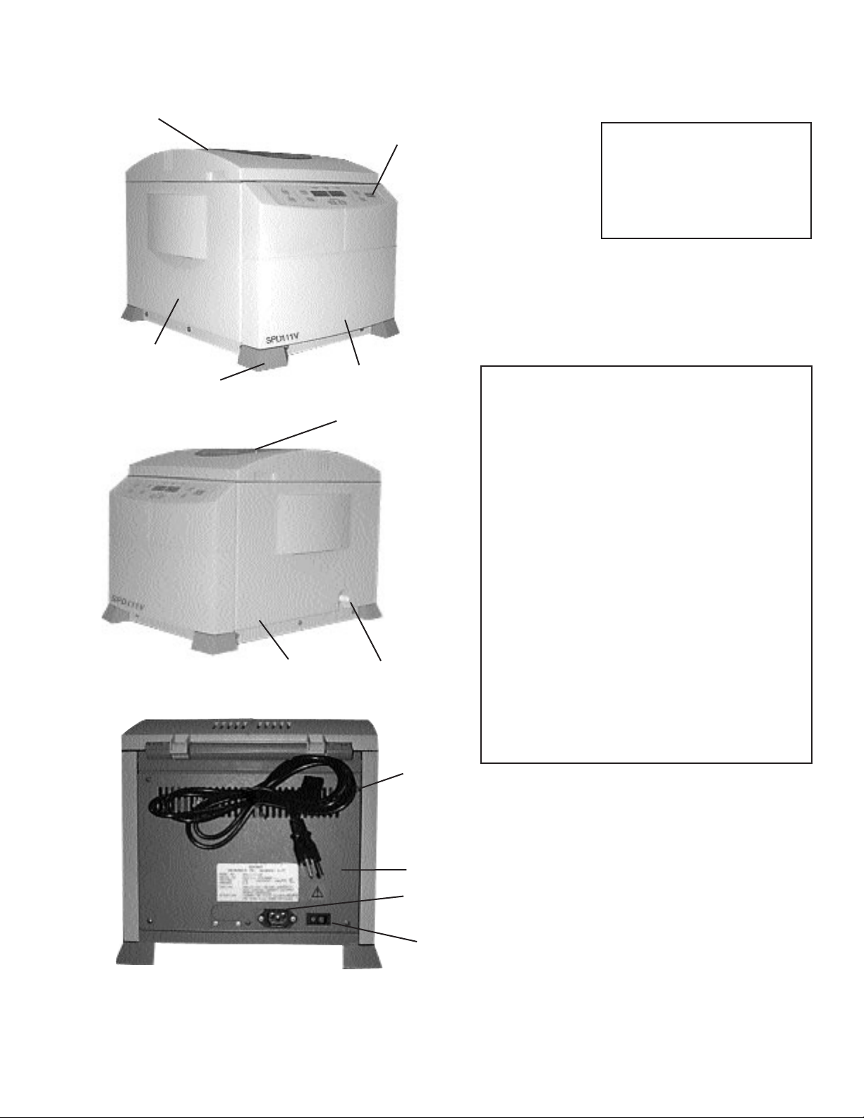
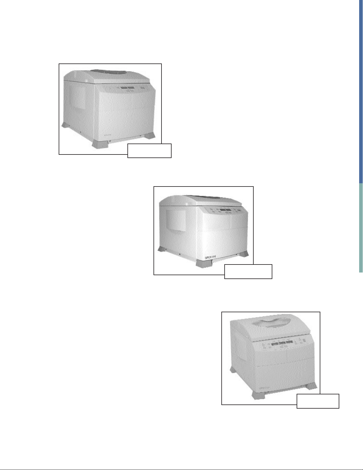
1. Top Cover (Radiant
Cover Optional)
2. Control Panel
3. Front Panel
4. Left Side Panel
5. Anti Skid/Vibration
6. Right Side Panel
7. Chamber View Window
8. Vacuum Port
9. AC Socket
10. Main On/Off Switch
11. Manual Cover
Lock Release
12. Rear Access Panel
1
2
3
4
5
6
12
8
9
10
11
7
Figure 1 = Front View
Figure 2 = Side View
Figure 3 = Back View
1.0 Overview of the SPD111V Unit
Fig. 1
Fig. 2
Fig. 3
1

1.1 INSTALLATION OF THE SPD111V
1. Unpack unit from the box and verify that all the parts match packing list.
2. Read instruction manual carefully! If assistance is required, contact
Thermo
3. If the unit is part of a larger system, use the vacuum tubing supplied to
hook up unit (See Figure 4).
4. Vacuum clamps must be put on vacuum ports of pump and SPD unit
(See item 8 on Figure 2 and Figure 4).
5. If being hooked up to existing system, simply attach vacuum tubing
to port on side of unit (See item 8, figure 2-vacuum port).
CAUTION - Cold trap should be in line between the vacuum source
and the SPD Unit.
RVT4104-
Refrigerated VaporTrap
VLP Vacuum
Pump SPD111V-
SpeedVac®
Concentrator
2
1.2 HOW TO HOOK UP THE SPD111V SPEEDVAC®SYSTEM
Figure 4-Rear View of System
Vacuum
Tubing
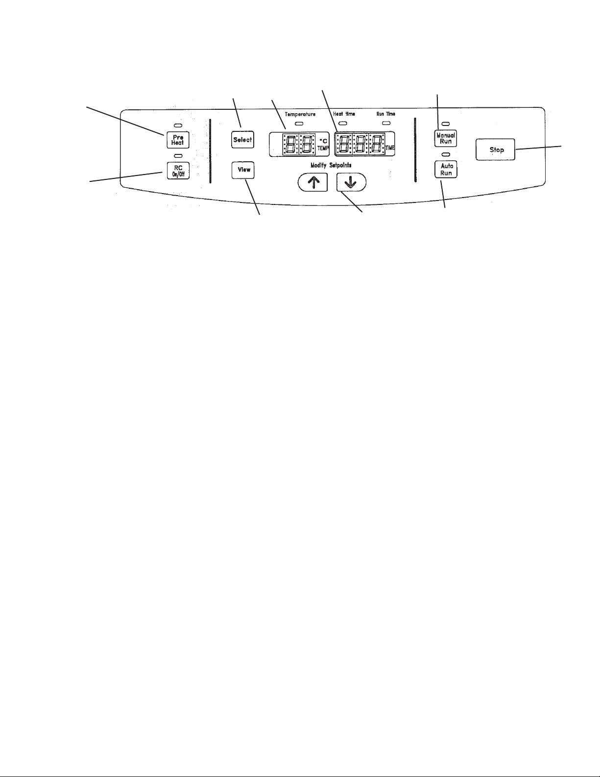
1. PRE-HEAT - use to pre-heat chamber to 45 °C prior to or between runs.
Once run is initiated the pre-heat stops.
2. RC ON/OFF - Use to add radiant heat to chamber.
Manual activation ON/OFF at any point during run.
Also will turn off at end of run.
3. SELECT - (located above temperature/time indicator), press this button to
select the parameters to be modified. Selection is from left to right.
GREEN light indicates the parameter to be modified.
4. MODIFY SETPOINT UP/DOWN - Modifies selected parameter.
5. AUTO RUN - Starts an automated run (See page 5).
6. MANUAL RUN - Starts a manual run (See page 4).
7. STOP - Terminates manual or auto run.
8. VIEW - Press to view. Displays preset parameters (during a run), displays
actual values when not running.
9. TEMPERATURE DISPLAY (GREEN DISPLAY) - Indicates set temperature or
actual temperature during a run in °C.
10. TIME DISPLAY (GREEN DISPLAY) - Indicates heat timer or run timer
setpoints. If in the process of a run it indicates elapsed time or time left.
19
7
6
5
4
3
2
10
8
2.0 SPD111V CONTROL PANEL
2.1 DESCRIPTION OF SPD111V CONTROL PANEL
3

This type of run will allow continuous running of the unit until it is turned off by
the user. The heat timer is activate and can be set to a user defined time.
1. Connect the unit to its required voltage.
2. Turn the power switch to ON, located on the back of the unit.
The cover lock, unlocks, allowing the top cover to be opened.
The display lights up, showing the following default values:
Temperature: 35 °C
Run Time: 2.00 HRS
Press “SELECT” to “HEAT TIME”: 1.00 HR default.
3. Place sample tubes in rotor so load is balanced.
Secure it with rotor supplied knob (hand tight). Close cover.
4. Using the “SELECT” button and the up/down keys, set temperature
between 35-80 °C, or “no”, for no heat.
5. Using the “SELECT” button and the up/down keys, select and modify
“HEAT TIME” to between 0.01and 9.59 hours or CCC (for continual
heating). When the heat timer expires, the heater will shut off, no matter
what the temperature setpoint is (except if CCC).
6. Press the “MANUAL RUN” button. The cover locks and rotor starts
turning. The decimal point blinks and the time display begins counting
up. The temperature rises to the set temperature. The “HEAT TIME”
will count down, and the SAV valve will actuate, applying vacuum to
the chamber.
NOTE: If the cover is not closed, the display will show “LID” and the
run will not start.
7. Press R/C for radiant cover heat. (Optional)
Press at any time to turn OFF and ON.
8. To end the manual run press “STOP” button. The display will show
”End”, the SAV valve will click allowing air to bleed into the chamber.
9. After the rotor stops spinning, the cover lock unlocks and the display
reverts to last set parameters.
10. Open cover and remove samples.
4
3.0 THE MANUAL RUN

3.1 THE AUTO RUN
An automated run will run the unit for a pre-defined time as selected by the
user.
1. Refer to the “MANUAL RUN” section for start up.
2. Place sample tubes in rotor so load is balanced. Secure it with
rotor supplied knob (hand tight). Close cover
3. To execute “AUTO RUN” perform the following steps:
a) Use “SELECT” button and up/down keys to select and modify
“TEMPERATURE, “HEAT TIME, “RUN TIME” parameters.
“RUN and HEAT TIME” can be set from 0.01 to 9.59 hours
(HEAT TIME also has CCC”).
b) Press “AUTO RUN” button to start the run. GREEN light above
“Auto Run” is on. The cover locks, and the rotor starts turning.
The time display is counting down in 1 minute intervals and the
decimal point blinks. The heat time is counting down (use select
button to view “HEAT TIME”). The temperature rises in 1 °C
increments to the set temperature. The SAV valve will actuate,
applying vacuum to the chamber.
c) Press R/C for radiant cover heat. (optional*)
Press at any time to turn OFF and ON.
NOTE: If the cover is not closed, the display will show “Lid” and the
run will not start.
d) Once the time decrements to 0.00 HRS. the run will automatically
stop, the display will show “End”. The SAV valve will click
allowing air to bleed into the chamber.
e) After the rotor stops spinning, the cover unlocks and the display
reverts to last set parameters.
f) Open the cover and remove samples.
GENERAL: During the run, display shows actual parameters.
To check set parameters, press “VIEW” button and
“SELECT”. The display will revert temporarily to set points.
5
*only units fitted with RCSPD.
6
CENTRIFUGE
TUBES
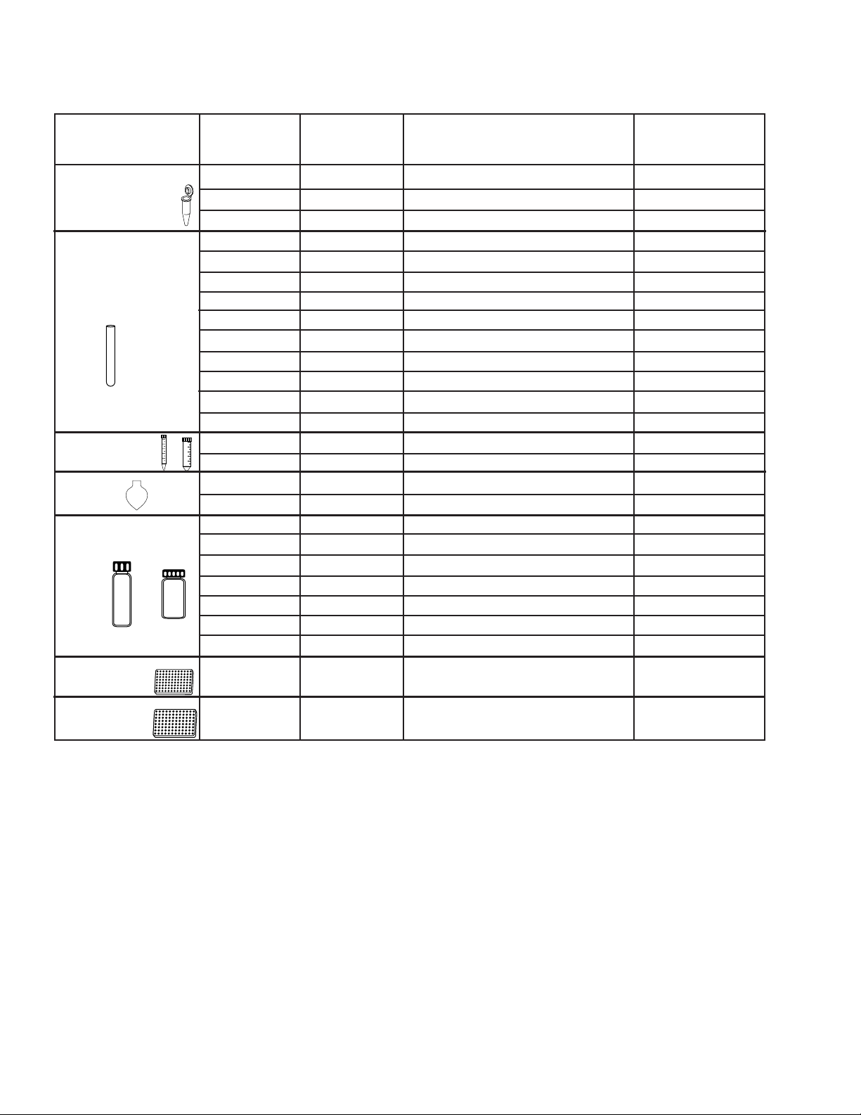
4.0 ROTOR SELECTION GUIDE
Working
Volume (ml)
Number
of Tubes
Description Rotor
Model
RH40-11
RH64-11
RH120-11
RH100-8
RH40-6
RH100-6
RH20-12
RH40-12
RH72-12
RH20-12
RH32-13
RH8-18
RH6-18-150
RH10-15
RH6-50
RH8-50
RH4-100
RH60-12-40
RH60-12-40
RH12-20
RH24-15
RH12-20
RH24-18
RH12-28
RH2MP
RHSW6M6
RHDW2MP
1.5 - 2.0 ml
1.5 - 2.0 ml
1.5 - 2.0 ml
0.5ml (8 x 29mm)
0.4ml (6x 50mm)
0.4ml (6 x 50mm)
12 x 75mm
1.5 - 2.0 (12 x 75mm)
12 x 75mm
13 x 100mm
13 x 100mm
18 x 100mm, 17 x 95, 16 x 100
18 x 150 mm
15ml conical (16 x 120mm)
50ml conical (28 x 115mm)
50ml pear shaped flask
100ml pear shaped flask
12 x 32mm
12 x 40mm vials
20 x 47mm v-vials
1 dram vials (15 x 45mm), 4ml
20 x 60mm v-vials
18 x 52mm mini-scintillation vials
28 x 60mm scintillation vials
Microplates
Microplates
Deepwell Microplates
40
64
120
100
40
100
20
40
72
10
32
8
6
10
6
8
4
60
60
12
24
12
24
12
2 plates
6 plates
2 plates
1.2 - 1.6
1.2 - 1.6
1.2 - 1.6
0.3
0.3
0.3
4
4
4
8
8
10
25
12
40
35
80
2
2.0
2.4
3
4
5.6
16
0.3
0.3
2.0
MICROCENTRIFUGE
TUBES
MICROTITER
PLATES(Shallow)
VIALS
GLASS AND
PLASTIC TUBES
FLASKS
DEEPWELL
PLATES

7
*The SPD units (SPD121P and SPD111V with a radiant cover) are better suited for limited
intermittent use of the solvents listed in Part II. Use of these solvents with the SPD111V
(without a radiant cover) and SPD101B may cause the lid material to become discolored and
cause potential damage. For additional technical assistance with respect to your solvent
choice, please contact the Applications Support Specialists at Thermo.
5.0 GUIDELINES FOR SOLVENT CHOICE
Part I: Solvents suited for the SPD111V unit
• Ethanol
• Methanol
• Water
• Acetonitrile
Part II: Solvents NOT suited for the SPD111V unit
• Methylene Chloride
• Chloroform
• Ethyl Acetate
• Hydrochloric Acid
• Trifluoroacetic Acid (TFA)
• Dimethyl Sulfoxide (DMSO)
Part III: All other solvents not listed above
Call Thermo application specialists to see if your solvent can
be used in the SPD111V concentrator.

8
6.0 MAINTENANCE/SERVICE
1. Maintenance: The SPD111V SpeedVac®requires no scheduled
maintenance.
2. Cleaning: The SPD111V SpeedVac®should be cleaned if solvents spill on
or inside the unit. Always clean up any spills immediately using
absorbent paper towels.
Always wear gloves when cleaning and dispose of paper towel in
appropriate designated refuse containers.
3. Replace chamber seal if cracked (Part number is 197-6020-00).
4. Outside of unit can be cleaned with dilute solution of soap and water.
5. For any other maintenance or service issues or service problems, please
contact Thermo.

9
7.0 SPECIFICATIONS/WARRANTY
Model: SPD111V
Bleeder Valve: Integrated Automatic Bleeder Valve
Temperature Range: 35 °C-80 °C
Volume Range/Tube: 18 x 150 mm
Maximum Tube Capacity: 6
Maximum Carrier Capacity: 2 (96-deepwell plates) see chart on page 6
Dimensions: (W x D x H) in.: 14 x 18 x 13
cm: 36 x 45 x 33
Weight: lbs. (kg) 31 (14)
Power requirements: 115 VAC/60Hz, 5.0A
(Part number SPD111V-115)
or
230 VAC/50Hz, 3.0A
(Part number SPD111V-230)
All Thermo products mentioned in this manual (except glassware) are warrant-
ed against defects in material and workmanship for one year after the date of
delivery to the original purchaser. Thermo’s warranty is limited to defective
materials and workmanship, and does not cover incidental or consequential
damages. Warranty work is subject to our inspection of the unit.
No instruments, equipment, or accessories will be accepted without a Return
Material Authorization (RMA) number issued by Thermo. Costs of shipping the
unit are not covered under warranty.
The warranty obliges you to follow the precautions in this manual. It is the
responsibility of the user to dispose of ALL materials in a manner in accordance
with all federal, state and local regulations. ALL RETURNED UNITS MUST BE
DECONTAMINATED AND FREE OF RADIOACTIVITY AND SHOULD BE
ACCOMPANIED WITH A DECONTAMINATION FORM. PLEASE CONTACT
THERMO TO HAVE THIS FORM FAXED TO YOU!
Under no circumstances shall Thermo be liable for damages due to the improp-
er handling or use of its products. Thermo assumes no liability, express or
implied, for your use of this equipment.

10
APPENDIX 1
Additional SPD111V System Set-ups
SEMI-INTEGRATED SYSTEM
SpeedVac®Concentrator
SPD111V
UVS400
Universal Vacuum Source
ANT100
Vacuum
Tubing
COMPONENT HIGH VACUUM SYSTEM
Flexible
Vacuum
Tubing
DVG50
SpeedVac®Concentrator
SPD111V
RVT400
Cold Trap
SCT120
Chemical Trap
VLP120
Vacuum Pump
Bleeder
Valve
Bleeder
Valve
SPD-SERIES SPEEDVAC®FAMILY
SPD101B
SPD111V
SPD121P

Belgium
Brussels
+32 2 482 30 30
Fax: +32 2 482 30 31
France
Cergy Pontoise Cedex
+33 1 34 32 51 51
Fax: +33 1 34 32 51 59
Germany
Dreieich
+49 6103 408 0
Fax: +49 6103 408 1222
Netherlands
Breda
+31 76 571 4440
Fax: +31 76 587 9757
Russia
Saint-Petersburg
+7 812 325 8045
Fax: +7 812 186 1194
Moscow
+7 095 755 9045
Fax: +7 095 755 9046
+34 93 2233154
Fax: +34 93 2230857
Barcelona
Spain
+46 8 742 03 90
Fax: +46 8 742 09 47
Stockholm
Sweden
+46 46 90 96 60
Fax: +46 46 32 87 70
Lund
+44 01256 81782
Fax: +44 01256 81792
Basingstoke, Hampshire
United Kingdom
+8610 5850 3588
Fax: +8610 6621 0847
Beijing
China
+8621 5465 7588
Fax: +8621 6445 7830
Shanghai
+852 2885 4613
Fax: +852 2567 4447
Wanchai
Hong Kong
+91 22 2778 1101
Fax: +91 22 2778 1103
Bangaalore
India
+81 45 453 9122
Fax: +81 45 453 9222
Yokohama-City
Japan
International Sales Office Locations
Bioscience
Technologies
Thermo Electron Corporation
866.9.THERMO (866.984.3766)
Molecular Biology
info.molbio@thermo.com
Sample Preparation
info.sampleprep@thermo.com
New Labs
newlabs@thermo.com
Services
services.biosciencetech@thermo.com
Laboratory Pipetting and Consumables
info.pipettes@thermo.com
Microplate Instrumentation
info.microplatei[email protected]
Laboratory Automation & Integration
info.labautomation@thermo.com
Controlled Environment
info.controlenv@thermo.com
Milford, MA 01757
Fax: 508.634.2199
450 Fortune Boulevard
Bioscience Technologies
www.thermo.com
© 2001-2004 Thermo Electron Corporation, All rights reserved.
Thermo Electron Corporation, SpeedVac, and Analyze, Detect, Measure,
Control, are trademarks of Thermo Electron Corporation.
Table of contents


