aldes C.Integra User manual

www.aldes.com
C.Integra
Notice d’installation et de maintenance
FR
Installation and maintenace instructions
EN
Installations- und Wartungsanleitung
DE
Instrucción de instalación y de mantenimiento
ES

2
Attention :
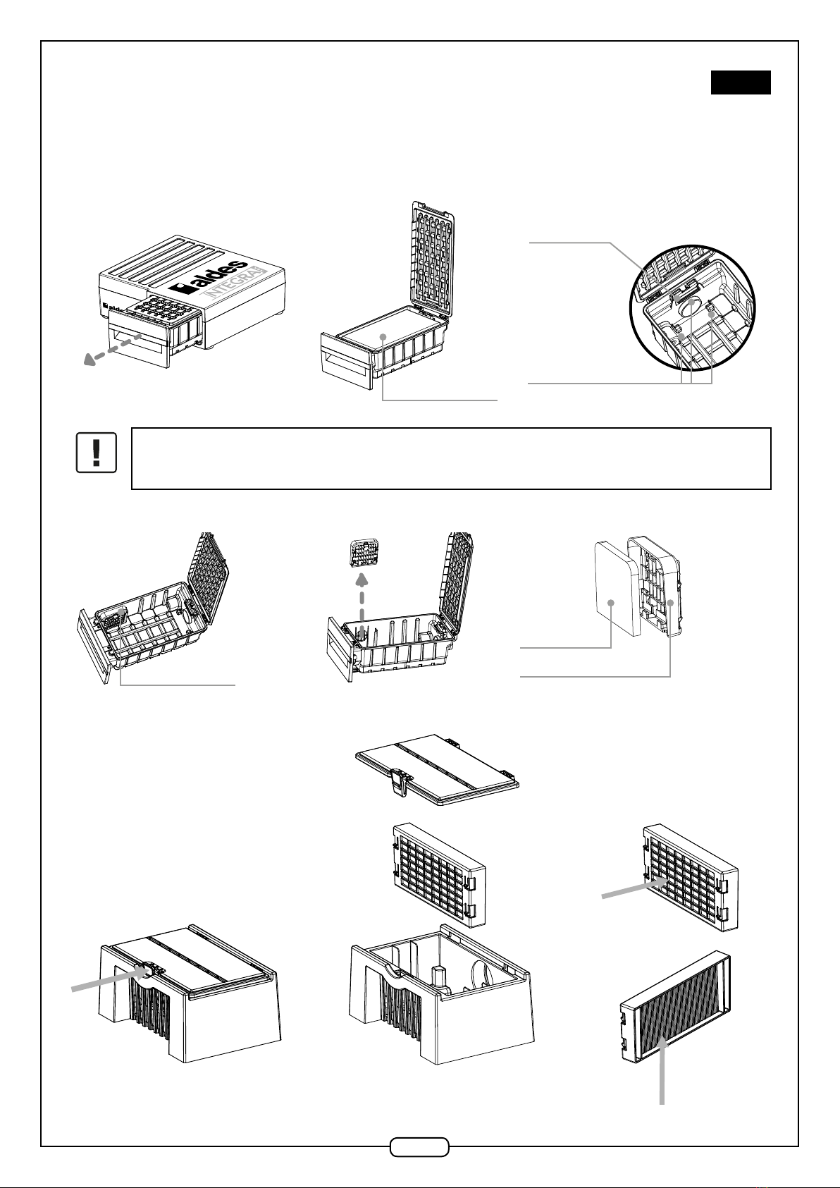
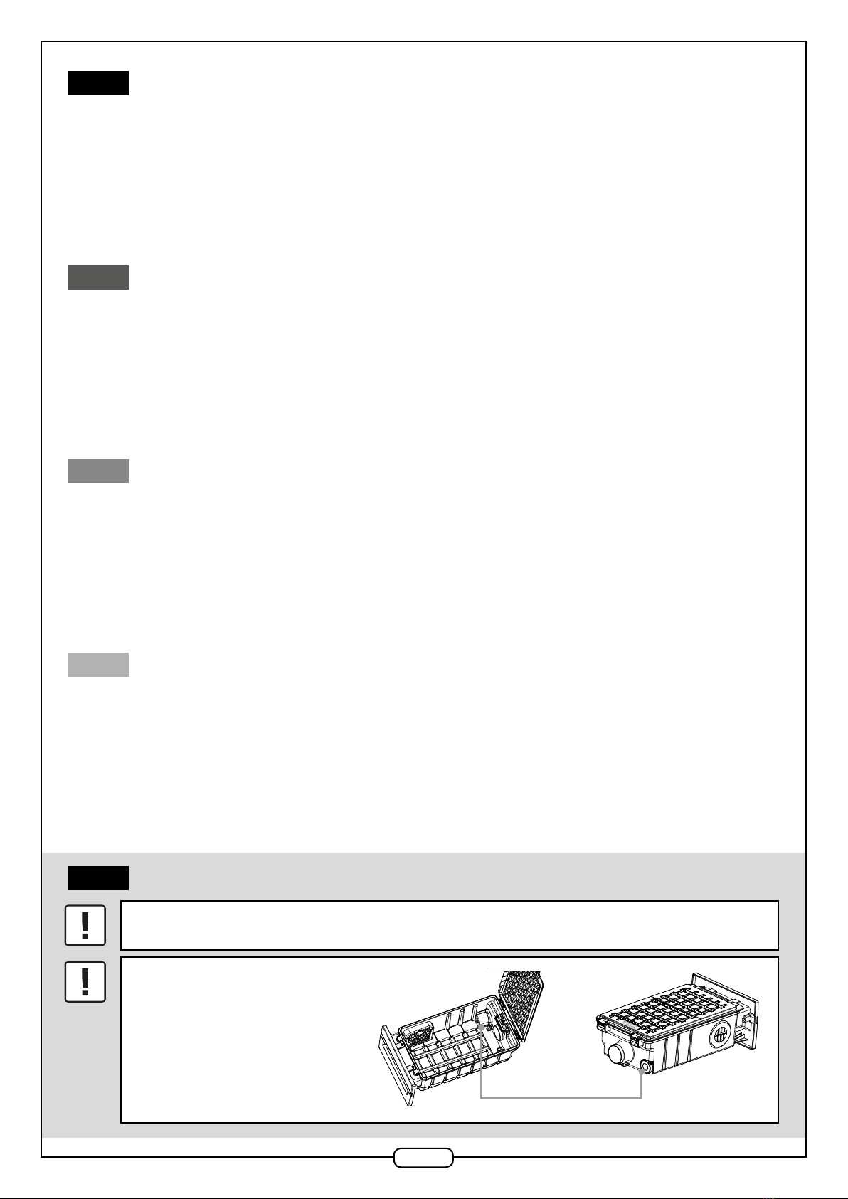
avant toute utilisation de la machine assurez-vous qu’un sac est mis en place dans le
compartiment à poussière
.
Le compartiment tiroir incorpore une valve régulatrice
(valve de sécurité), qui assure une circulation d’air
neuf supplémentaire an de protéger le moteur.
NE COUVREZ PAS
LA VALVE RÉGULATRICE !
www.
INTEGRAVAC
.com
Valve régulatrice
FR
TABLE DES MATIÈRES
1. DESCRIPTION GÉNERALE ...............................................................................................................................3
2. MONTAGE ......................................................................................................................................................5
3. ENTRETIEN ...................................................................................................................................................9
4. RÉSOLUTION DES PROBLÈMES....................................................................................................................10
5. GARANTIE....................................................................................................................................................11
6. RÉGLEMENTATIONS ENVIRONNEMENTALES .................................................................................................11
7. GABARIT DE DÉCOUPE PLINTHE ..................................................................................................................43
EN
CONTENTS
1. GENERAL DESCRIPTION ...............................................................................................................................13
2. INSTALLATION..............................................................................................................................................15
3. SERVICING ...................................................................................................................................................19
4. PROBLEM SOLVING ......................................................................................................................................20
5. WARRANTY ..................................................................................................................................................21
6. ENVIRONMENTAL REGULATIONS ..................................................................................................................21
7. PLINTH CUTOUT TEMPLATE..........................................................................................................................43
DE
INHALT
1. ALLGEMEINE BESCHREIBUNG.......................................................................................................................23
2. MONTAGE ....................................................................................................................................................25
3. INSTANDHALTUNG .......................................................................................................................................29
4. PROBLEMLÖSUNG .......................................................................................................................................30
5. GARANTIE....................................................................................................................................................31
6. UMWELTVORSCHRIFTEN ..............................................................................................................................31
7. SCHABLONE ZUM AUSSCHNEIDEN DER LEISTE ............................................................................................43
ES
ÍNDICE
1. DESCRIPCIÓN GENERAL...............................................................................................................................33
2. MONTAJE.....................................................................................................................................................35
3. MANTENIMIENTO.........................................................................................................................................39
4. RESOLUCIÓN DE LOS PROBLEMAS...............................................................................................................40
5. GARANTÍA....................................................................................................................................................41
6. REGLAMENTACIONES MEDIOAMBIENTALES..................................................................................................41
7. PLANTILLA DE CORTE DE RODAPIÉ ..............................................................................................................43
FR

3
FR
1. DESCRIPTION GÉNÉRALE
La centrale d’aspiration C.Integra est un aspirateur centralisé compact à sac. Le compartiment à sac est situé dans le tiroir.
1.1. Caractéristiques techniques
- Modèle : C.Integra 11071142
- Alimentation : 230 V - 50/60Hz
- Volume sac à poussières : 4L
- Système de ltration :
Filtre Principal : sac à poussière à 5 feuilles
Filtre Secondaire : ltre moteur
MODÈLE PUISSANCE DÉBIT DÉPRESSION AIRWATTS
INTEGRA 1.100 W 162 M3/H 2700 MM/H2O 400 AW
- Moteur : Thru-Flow à haute vitesse
- Poids Net colis : 10 kg.
1.2. Ecorché produit
1 x C.INTEGRA Tiroir renfermant le compartiment Compartiment
pour sac à poussière pour sac à poussière
370mm
330mm 20mm
200mm
100mm
188mm
183mm
125mm
388mm
52mm
100mm 183mm
VUE DE CÔTÉ
VUE DE DERRIÈRE
Connexion au réseau de refoulement
Interrupteur marche/arrêt
Prise pour câble d’alimentation
Connexion basse tension
aux prises d’aspiration
Connexion au
réseau d’aspiration

4
1.3. Composants et accessoires
1 x plaque décorative blanche
pour face avant tiroir
1 x plaque décorative inox
brossé pour face avant tiroir
1 x poignée de tiroir
blanche
1 x poignée de tiroir
chromée
1 x barre de xation pour installation
en dessous d’un meuble
2 x tuyau exible 40 cm de longueur
par Ø 50 mm pour brancher
la centrale au réseau de conduits
d’aspiration et au refoulement
1 x jeu de 5 sacs à poussière
de remplacement
1 x support et 2 x xations
1 x câble d’alimentation
1 x câble de branchement à la ligne
basse tension
4 x pieds réglables pour installer
la centrale au mur
4 x pieds réglables courts pour installer la centrale en
dessous d’un meuble de cuisine

5
FR
2. MONTAGE
Il existe plusieurs modes d’installation pour cette centrale : horizontal sous un meuble ou vertical contre une paroi.
2.1. Position horizontale sous un meuble
5IMPORTANT ! AVANT DE REPLACER LA PLINTHE :
- assurez-vous d’avoir soit connecté soit fait en sorte que les câbles 230 V et 24 V soient accessibles pour le raccordement
électrique de la centrale ;
- mettez l’interrupteur de la centrale en position ON.
6Replacez la plinthe et xez-la solidement. La xation de la plinthe doit être sufsamment robuste pour résister aux contraintes
mécaniques imposées par la manipulation du tiroir. Si ce n’est pas le cas, renforcez la xation de la plinthe.
4
Mettez en place la barre de xation et dévissez les pieds de xation pour bloquer la centrale sous le meuble.
SURFACE INFÉRIEURE DU MEUBLE DE CUISINE
SOL FINI
4 PIEDS RÉGLABLES
2
Assurez-vous que l’emplacement de la centrale
sous le meuble n’empêche pas la xation de la
plinthe sur le pied des meubles.
Découpez la plinthe selon les dimensions
indiquées. Aidez-vous du gabarit page 13.
200mm
125mm
DIMENSIONS DE LA DECOUPE
DE LA PLINTHE
Central Vacuum Systems
Hauteur max. des pieds réglables longs : 5,5 cm
Hauteur max. des pieds réglables courts
(montés par défaut sur la centrale) : 2,8 cm
1Assurez-vous que la hauteur de votre plinthe
est compatible avec ce type d’installation.
La hauteur de plinthe requise est de
minimum 145 mm.
3Raccordez les tuyaux exibles à l’entrée et à la sortie d’aspiration de la centrale. Raccordez les câbles 230V et 24 V à la centrale (voir
partie 2.3 et 2.4). Positionnez la centrale sous le meuble en vous assurant que l’avant du tiroir soit bien devant la plinthe une fois celle-ci
replacée. Raccordez les tuyaux exibles à vos conduits d’aspiration et de refoulement sans les coller (pour permettre une maintenance
ultérieure). Si le bas du tiroir touche le sol, si la longueur des patins est insufsante ou le sol inégal, servez-vous des patins sous la centrale
pour la rehausser.
145mm
Hauteur mini 145 mm

6
2.2. Position verticale contre une paroi (mur, intérieur d’un meuble)
1
2
3
4
Fixez le support à la paroi avec les xations adaptées.
Vissez les pieds de xation au support sur la centrale et remplacez les pieds réglables courts de la centrale par les pieds réglables longs
fournis.
Positionnez la centrale dans le sens souhaité.
Pour achever la xation, dévissez les pieds réglables jusqu’au verrouillage de la centrale contre la paroi.
Vissez le support soit à un panneau intérieur
d’un meuble soit au mur d’une pièce technique
4 x pieds réglables longs
pour installation verticale
contre une paroi 2 x Fixations support
Attention, assurez-vous que la position de la centrale permette d’accéder au tiroir pour remplacer le sac à poussière.

7
FR
2.3. Raccordement électrique et mise en service
Branchez le cordon d’alimentation sur la prise 230V.
Raccordez le cordon 24V aux prises d’aspiration du logement.
Placez le sac à poussière dans le tiroir en prenant garde de le xer correctement à l’aide de la pince prévue à cet effet.
Mettez le bouton de mise en marche sur ON.
Attention :
le raccordement électrique sera réalisé par un professionnel selon les règles de la norme
NF C 15-100
.
Interrupteur marche-arrêt
Connexion 230 V pour câble
d’alimentation
Connexion basse tension aux
prises d’aspiration
2.4. Raccordement au réseau d’aspiration
Raccordez les conduits exibles fournis sur l’entrée d’aspiration et le refoulement de la centrale. Raccordez les tuyaux exibles à vos conduits
d’aspiration et de refoulement sans les coller (pour permettre une maintenance ultérieure).
Attention :
Ne pas coller
Refoulement
Entrée d’air
Dans la mesure du possible (type de centrale et conguration du logement), nous conseillons de refouler l’air d’aspiration à l’extérieur du logement.
2Passage en diamètre 100 mm sur minimum 0,5 m avant la grille
à l’aide d’un tampon réducteur 1
3Caractéristiques de la grille en façade: minimum 100 mm de diamètre
avec un passage d’air minimum de 78 cm
1
2 3
2 coudes 90° Max.

8
S’il n’est pas possible de raccorder le refoulement de la centrale à un réseau de refoulement vers l’extérieur du logement, commandez le boîtier
de refoulement 11071174 qui permet de ltrer l’air rejeté par la centrale. Connectez le boîtier de refoulement au tuyau exible du refoulement de la
centrale et placez le boîtier à un endroit accessible pour permettre le changement régulier du ltre. Si le tuyau exible n’est pas assez long, rajoutez
une longueur de conduit pour atteindre la zone voulue.
Installation du boîtier de refoulement en fonction du mode d’installation de la centrale.
- Centrale installée sous un meuble :
Positionnement du boîtier dans un endroit accessible an de permettre le changement régulier du ltre (Réf. 11071175).
Si nécessaire, rajouter une partie de réseau Ø 51mm (longueur + max 1 coude + manchon F-F) pour placer le boîtier à l’endroit choisi.
Ø 51mm
+
- Centrale installée sur une paroi verticale :
Ø 51mm
+
Si nécessaire, rajouter une partie de réseau Ø 51mm (longueur + max 1 coude + manchon F-F) pour placer le boîtier à l’endroit choisi.
2.5. Personnalisation de la face avant du tiroir
Le tiroir compartiment à sac à poussière est livré avec 2 jeux de 2 plaques de nition auto-collantes pour vous permettre de l’accorder à la couleur
de vos meubles : un jeu de plaques blanches et un jeu de plaques en inox brossé. Avant de coller les plaques, nettoyez la face avant du tiroir.
Une fois les plaques collées, retirez leur lm protecteur.
Le tiroir est équipé par défaut d’une poignée blanche. Elle peut être remplacée par la poignée chromée fournie en accessoire : il suft de dévisser la
poignée blanche et de visser la poignée chromée à la place.
1 x plaque décorative blanche
adhésive pour face
avant tiroir
1 x plaque décorative inox
brossé adhésive pour face
avant tiroir
1 x poignée de tiroir blanche 1 x poignée de tiroir chromée

9
FR
3. ENTRETIEN
3.1. Changement de sac
1. Retirez le tiroir de son logement à l’aide de sa poignée.
2. Ouvrez le couvercle du compartiment à sac pour accéder au sac à poussière. Retirez le sac en place, fermez le sac à l’aide de l’opercule
autocollant prévu à cet effet avant de le jeter. Mettez en place le sac neuf.
Sac à poussière
Zone d’insertion de la
languette du sac
Pince de maintien
du sac
Attention :
il est essentiel que le sac à poussière soit installé correctement et le ltre moteur en place
lors du fonctionnement de la centrale. Sans ces précautions, des poussières risqueraient de pénétrer
dans la chambre moteur et entraîneraient des dommages sur le moteur.
3.2. Changement de la cartouche filtre
Filtre moteur Support de ltre carbone
Filtre carbone
3.3. Procédure de remplacement du filtre
2. Remplacer le ltre en prenant garde
d’orienter la partie arrière du ltre vers
l’arrière du boîtier de refoulement.
Partie arrière :
ltre carbone
Partie avant
blanche : ltre HEPA.
1. Appuyer pour retirer le couvercle

10
4. RÉSOLUTION DES PROBLÈMES
En cas de dysfonctionnement de la centrale, veillez procéder aux vérications suivantes.
4.1. La performance d’aspiration de la centrale est dégradée
4.2. La centrale ne démarre pas du tout
Vériez que le tiroir est poussé à fond dans son logement. Par sécurité, un système empêche la centrale de démarrer si le tiroir n’est pas en place.
Vériez que le cordon d’alimentation de la machine est bien branché.
Si le problème persiste, contactez votre installateur.
4.3. Si vous avez aspiré du liquide par erreur, débranchez immédiatement l’alimentation
électrique de la centrale et contactez votre installateur.
OUI
NON
NON
OUI
La performance d’aspiration est dégradée ?
1. Vider la cuve et nettoyer les filtres
Alors il y a un bouchon dans le réseau d’aspiration.
Faites plusieurs cycle de démarrage arrêt de la centrale
à l’aide des boutons de la centrale en laissant la centrale
tourner 30 secondes à chaque cycle. La fluctuation de débit
air qui en résultera devrait faire bouger les débris en les
aspirants vers la centrale.
Si l’une de vos prises d’aspiration fonctionne correctement,
tentez d’aspirer le bouchon en plaçant l’embout du flexible
à l’entrée de la prise encombrée.
Si aucune prise ne fonctionne, procédez avec un aspirateur
classique.
Si le problème persiste, contactez votre installateur.
La performance d’aspiration est améliorée ?
NON
OUI
Alors soit il y a un problème de fuite dans le réseau soit
il y a un problème moteur.
Contactez votre installateur.
Tout est OK
Tout est OK
NON
OUI
2. Déconnecter le conduit d’aspiration de l’entrée d’air et
constatez si l’aspiration est améliorée à l’entrée d’air.
La performance d’aspiration est améliorée ?

11
FR
5. GARANTIE
Conditions générales de garantie
Se reporter aux conditions générales de vente sur le site www.aldes.fr.
Le système doit être installé par un professionnel qualié suivant les règles de l’art, les normes en vigueur et les prescriptions de nos notices.
Durée de la garantie
Les éléments électriques et pièces amovibles bénécient d’une garantie de 2 ans.
Conditions d’exclusion de la garantie
Sera exclue de cette garantie, toute défaillance de l’installation liée à un non respect des préconisations du fabricant, au non respect des normes et
réglementations en vigueur, ou à un manque d’entretien.
Les sous-ensembles, tels que les moteurs, ne sont garantis que s’ils n’ont jamais été démontés. Les frais ou dégâts dus à une installation ou à des
difcultés d’accès ne peuvent en aucun cas être imputés au fabricant.
PENSEZ A VOUS ENREGISTRER
Pour bénécier du meilleur de la garantie Aldes, enregistrez votre Centrale d’aspiration
en ligne en toute simplicité.
Munissez-vous du numéro de série afché sur le produit puis ashez ce QR code ou rendez-
vous sur le site support.aldes.com
6. RÉGLEMENTATIONS ENVIRONNEMENTALES
DEEE : Ce produit ne doit pas être jeté avec les déchets ménagers. En n de vie ou lors de son remplacement, il doit être remis à une déchetterie,
auprès d’un revendeur ou d’un centre de collecte.
ALDES adhère à l’éco-organisme ES R http://www.es-r.fr/
ALDES a conçu ce produit pour être facilement recyclé. En participant au tri sélectif des déchets, vous contribuez au recyclage de ce produit et à la
protection de l’environnement.
REACH : En l’état de nos connaissances, cet article ne contient pas de substance candidate à autorisation à plus de 0,1% de son poids selon la liste
maintenue par l’ECHA.
- Pour connaître la disponibilité des pièces détachées, rendez-vous sur Aldes.fr
- Absence de pièces plastiques > 25 grammes contenant des retardateurs de amme bromés.
7. GABARIT DE DÉCOUPE PLINTHE (VOIR PAGE 43)

12
Caution:
abefore using the machine, make sure that a bag is inserted in the dust compartment.
The drawer compartment has a control valve
(safety valve) that circulates additional outdoor air
to protect the motor.
DO NOT COVER
THE CONTROL VALVE!
www.
INTEGRAVAC
.com
Control valve
EN
CONTENTS
1. GENERAL DESCRIPTION ...............................................................................................................................13
2. INSTALLATION..............................................................................................................................................15
3. SERVICING ...................................................................................................................................................19
4. PROBLEM SOLVING ......................................................................................................................................20
5. WARRANTY ..................................................................................................................................................21
6. ENVIRONMENTAL REGULATIONS ..................................................................................................................21
7. PLINTH CUTOUT TEMPLATE..........................................................................................................................43
EN

13
EN
1. GENERAL DESCRIPTION
The C.Integra suction unit is a compact centralised vacuum cleaner with bag. The bag compartment is located in the drawer.
1.1. Technical details
- Model: C.Integra 11071142
- Power supply: 230 V - 50/60Hz
- Dustbag volume: 4 L
- Filtration system:
Main lter: dustbag with ve leaves
Secondary lter: motor lter
- Motor: High-speed Thru-Flow
- Package net weight: 10 kg.
1.2. Product exploded view
1 x C.INTEGRA Drawer enclosing Dustbag compartment
the dustbag compartment
370mm
330mm 20mm
200mm
100mm
188mm
183mm
125mm
388mm
52mm
100mm 183mm
VUE DE CÔTÉ
VUE DE DERRIÈRE
Connection to the exhaust ductwork
Start/stop switch
Power lead socket
Low voltage connection
for suction inlets
Connection to the
suction ductwork
MODEL POWER AIRFLOW NEGATIVE PRESSURE AIRWATTS
INTEGRA 1.100 W 162 M3/H 2700 MM/H2O 400 AW
SIDE VIEW
REAR VIEW

14
1.3. Components and accessories
1 x white decorative plate for
drawer front
1 x brushed stainless steel
decorative plate for drawer front
1 x white drawer
handle
1 x chrome-plated
drawer handle
1 x xing rod for installation underneath
a kitchen unit
2 x exible hoses 40 cm long
by Ø 50 mm to plug the unit into the
suction ductwork and exhaust
1 x set of ve spare dustbags
1 x bracket and 2 x xings
1 x power lead
1 x connection cable
to the low voltage line
4 x adjustable feet to install the unit
on the wall
4 x short adjustable feed to install the unit underneath
a kitchen unit

15
EN
2. INSTALLATION
This unit can be installed in several ways: horizontally under a kitchen unit or vertically against a wall.
2.1. Horizontal position under a kitchen unit
5IMPORTANT! BEFORE PUTTING THE PLINTH BACK:
- make sure that you have connected the 230 V and 24 V cables or that they can be accessed to connect the unit to the power
supply;
- move the unit switch to the ON position.
6Put the plinth back and x it rmly. The plinth xing must be strong enough to withstand the mechanical constraints imposed by operating
the drawer. If this is not the case, reinforce the plinth xing.
4
Insert the xing rod and loosen the xing feet to block the unit under the kitchen unit.
SURFACE INFÉRIEURE DU MEUBLE DE CUISINE
SOL FINI
4 PIEDS RÉGLABLES
2
Make sure that locating the unit underneath the
kitchen unit does not prevent xing the skirting
board to the kitchen unit feet.
Cut out the plinth to the dimensions indicated.
Use the template on page 43 to help you.
200mm
125mm
DIMENSIONS DE LA DECOUPE
DE LA PLINTHE
Central Vacuum Systems
Max. height of long adjustable feet: 5.5 cm
Max. height of short adjustable feet
(tted to the unit by default): 2.8 cm
1Make sure that the height of your plinth is
compatible with this type of installation.
The plinth must be at least 145 mm high.
3Connect the exible hoses to the unit’s suction inlet and outlet. Plug the 230 V and 24 V cables into the unit (see sections 2.3 and 2.4).
Position the unit underneath the kitchen unit making sure that the drawer front is in front of the plinth once this has been reinserted.
Connect the exible hoses to your suction and exhaust ductwork without sticking them (to allow subsequent maintenance). If the drawer
bottom touches the oor, the glides are not long enough or the oor is uneven. Use glides under the unit to raise it.
145mm
Min. height 145 mm
PLINTH CUTOUT DIMENSION
FINISHED FLOOR
4ADJUSTABLE FEET
INSIDE SURFACE OF THE KITCHEN UNIT

16
2.2. Vertical position against a wall (dwelling wall, inside a kitchen unit)
1
2
3
4
Fix the bracket to the wall with the appropriate xings.
Screw the xing feet to the bracket on the unit and change the short adjustable feet on the unit for the long adjustable feet supplied.
Position the unit in the desired direction.
To complete the xing, loosen the adjustable feet until the unit is locked against the wall.
Screw the bracket to a panel inside the kitchen
unit or to the wall in a technical room.
4 x long adjustable feet for
vertical installation against
a wall 2 x bracket xings
Caution, make sure that the unit is positioned to allow access to the drawer to replace the dustbag.

17
EN
2.3. Electrical connection and commissioning
Plug the power lead into the 230 V socket.
Connect the 24 V lead to the suction inlets in the dwelling.
Insert the dustbag into the drawer taking care to x it properly using the clip provided for this purpose.
Move the run button to ON.
Caution:
the unit will be connected to the power supply by a professional as per the rules of standard
NF C 15-100.
Start-stop switch
230 V connection
for power lead
Low voltage connection
for suction inlets
2.4. Connection to the suction ductwork
Connect the exible hoses provided to the unit’s suction inlet and exhaust. Connect the exible hoses to your suction and exhaust ductwork without
sticking them (to allow subsequent maintenance).
Caution:
Do not stick
Exhaust
Air inlet
Whenever possible (type of unit and accommodation conguration), we advise discharging the suction air outside the dwelling.
2Diameter 100 mm passage on minimum 0.5 m in front of the grille
using a reducing plug 1
3Grille characteristics on façade: minimum 100 mm diameter with
minimum air passage of 78 cm
1
2 3
2 coudes 90° Max.
2 90° elbows max.

18
Where the unit exhaust cannot be connected to ductwork discharging outside the dwelling, order exhaust unit 11071174 that can lter the air
discharged by the unit. Connect the exhaust unit to the exible hose on the vacuum unit’s exhaust and install it in an accessible location so that the
lter can be changed regularly. If the exible hose is not long enough, add a length of duct to reach the desired area.
Installation of the exhaust unit based on the installation method for the vacuum unit.
- Vacuum unit installed under a kitchen unit:
Positioning the exhaust unit in an accessible location so that the lter can be changed regularly (ref. 11071175).
If necessary, add a ductwork section Ø 51 mm (length + 1 elbow max. + F-F sleeve) to place the unit in the chosen location.
Ø 51mm
+
Unit installed on a vertical wall:
Ø 51mm
+
If necessary, add a ductwork section Ø 51 mm (length + 1 elbow max. + F-F sleeve) to place the unit in the chosen location.
2.5. Customising the drawer front
The dustbag compartment drawer is supplied with two sets of two self-adhesive nishing plates so that you can tie it in with the colour of your
kitchen units - one set of white plates and one in brushed steel. Clean the drawer front before sticking on the plates.
Remove the protective lm from the plates once stuck.
The drawer is equipped with a white handle by default. It can be changed for the chrome-plated handled supplied as an accessory. Simply unscrew
the white handle and screw the chrome-plated handle in instead.
1 x adhesive white decorative
plate for drawer front
1 x adhesive brushed
stainless steel decorative
plate for drawer front
1 x white drawer handle 1 x chrome-plated drawer
handle

19
EN
3. SERVICING
3.1. Changing the bag
1. Pull the drawer out of its housing using its handle.
2. Open the dustbag compartment lid to access the dustbag. Withdraw the bag in place, close it using the self-adhesive blanking plate provided for
this purpose and throw it away. Insert the new bag.
Dustbag
Bag tongue insertion
area
Bag holding clip
Caution:
it is essential to install the dustbag properly and insert the motor lter when the unit is
operating. Without these precautions, dust may well enter the motor chamber and damage the
motor.
3.2. Changing the filter cartridge
Motor lter Carbon lter bracket
Carbon lter
3.3. Procedure for changing the filter
2. Change the lter taking care to point the
back of the lter towards the rear of the
exhaust unit.
Back section:
carbon lter
White front section:
HEPA lter.
1. Press to remove the lid

20
4. PROBLEM SOLVING
Please perform the following checks if the unit malfunctions.
4.1. The unit suction efficiency has deteriorated
YES
NO
NO
YES
Has suction efficiency deteriorated?
1. Empty the tank and clean the filters
There is therefore a blockage in the suction ductwork.
Run several stop-start cycles on the unit using its buttons,
letting the unit run for thirty seconds at each cycle. The
resulting airflow fluctuation should move the debris by
sucking it towards the unit.
If one of your suction inlets is working properly, try to suck
out the blockage by packing the end of the hose at the
entry to the congested inlet.
Use a traditional vacuum cleaner if no inlet is working.
Contact your installer if the problem persists.
Has suction efficiency improved?
NO
YES
There is therefore a leak problem in the ductwork or a
problem with the motor.
Contact your installer.
Everything is OK
Everything is OK
NO
YES
2. Disconnect the suction duct from the air inlet and see
whether the suction is improved at the air inlet.
Has suction efficiency improved?
4.2. The unit does not start at all
Check that the drawer is pushed as far as it will go into its housing. For safety reasons, a system prevents the unit from starting if the drawer is not in
place. Check that the power lead for the machine is plugged in.
Contact your installer if the problem persists.
4.3. If you have sucked up liquid by mistake, unplug the unit immediately and contact your
installer.
This manual suits for next models
1
Table of contents
Languages:
Popular Medical Equipment manuals by other brands

Fahl
Fahl LARYVOX TAPE Instructions for use

Cardioline
Cardioline ECG100+ user manual

Ivy Biomedical Systems
Ivy Biomedical Systems 580076 Regulatory information

MICROPOINT
MICROPOINT qLabs ElectroMeter Q-3 Pro user manual

WittRock
WittRock Integris 2002 Service manual

Lifelines
Lifelines trackit T4 user manual