Shimmer ShimmerCapture User manual

ShimmerCapture
User Manual
Rev 0.5a

Copyright © Shimmer 2014
Realtime Technologies Ltd ShimmerCapture User Manual
All rights reserved Rev 0.5a
2
Legal Notices and Disclaimer
Redistribution IS permitted provided that the following conditions are met:
Redistributions must retain the copyright notice, and the following disclaimer. Redistributions in electronic form
must reproduce the above copyright notice, this list of conditions and the following disclaimer in the
documentation and/or other materials provided with the document.
Neither the name of Shimmer Research, or Realtime Technologies Ltd. nor the names of its contributors may
be used to endorse or promote products derived from this document without specific prior written permission.
THIS DOCUMENT IS PROVIDED BY THE COPYRIGHT HOLDERS AND CONTRIBUTORS "AS IS" AND
ANY EXPRESS OR IMPLIED WARRANTIES, INCLUDING, BUT NOT LIMITED TO, THE IMPLIED
WARRANTIES OF MERCHANTABILITY AND FITNESS FOR A PARTICULAR PURPOSE ARE DISCLAIMED.
IN NO EVENT SHALL THE COPYRIGHT OWNER OR CONTRIBUTORS BE LIABLE FOR ANY DIRECT,
INDIRECT, INCIDENTAL, SPECIAL, EXEMPLARY, OR CONSEQUENTIAL DAMAGES (INCLUDING, BUT
NOT LIMITED TO, PROCUREMENT OF SUBSTITUTE GOODS OR SERVICES; LOSS OF USE, DATA, OR
PROFITS; OR BUSINESS INTERRUPTION) HOWEVER CAUSED AND ON ANY THEORY OF LIABILITY,
WHETHER IN CONTRACT, STRICT LIABILITY, OR TORT (INCLUDING NEGLIGENCE OR OTHERWISE)
ARISING IN ANY WAY OUT OF THE USE OF THIS DOCUMENT, EVEN IF ADVISED OF THE
POSSIBILITY OF SUCH DAMAGE.

Copyright © Shimmer 2014
Realtime Technologies Ltd ShimmerCapture User Manual
All rights reserved Rev 0.5a
3
Table of Contents
1. Introduction .........................................................................................................................4
1.1. Scope.......................................................................................................................................4
1.2. Pre-Requisites .........................................................................................................................4
2. ShimmerCapture on Windows .............................................................................................. 6
2.1. Starting ShimmerCapture........................................................................................................6
2.2. Connecting to a Shimmer........................................................................................................6
2.3. Configuring the Shimmer........................................................................................................8
2.3.1. Configuration Window....................................................................................................8
2.3.2. Configuring with/without the Shimmer Dock...............................................................12
2.4. Configuring a Shimmer GSR+ Expansion Board ....................................................................13
2.5. Configuring a Shimmer ExG Module.....................................................................................14
2.6. Streaming Data .....................................................................................................................18
2.7. Status bar ..............................................................................................................................19
2.8. Disconnecting from a Shimmer.............................................................................................20
2.9. Saving data to a local file ......................................................................................................20
2.10. Show/Hide Graphs ............................................................................................................21
2.11. 3D Orientation ..................................................................................................................21
2.11.1. 3D Orientation Visualisation .........................................................................................22
3. ShimmerCapture on Linux................................................................................................... 25
3.1. Pairing Bluetooth devices .....................................................................................................25
3.1.1. Requirements................................................................................................................25
3.2. Using the ShimmerCapture executable ................................................................................26
4. Appendix............................................................................................................................ 27
4.1. ShimDv2 File Format.............................................................................................................27

Copyright © Shimmer 2014
Realtime Technologies Ltd ShimmerCapture User Manual
All rights reserved Rev 0.5a
4
1. Introduction
ShimmerCapture is a host side (PC) application that allows users to display and save data received
from a single Shimmer device streaming over Bluetooth. The application allows the configuration of
a range of parameters on the Shimmer3, and is primarily designed to demonstrate Shimmer’s
functionality. ShimmerCapture works in conjunction with the Shimmer3 LogAndStream firmware to
allow simultaneous streaming of data over Bluetooth as well as the logging of data to the on-board
microSD card. The current release of ShimmerCapture is available for use in Microsoft Windows
environments or in Linux.
1.1. Scope
ShimmerCapture is not intended to be the answer to all host side application requirements but
instead as a quick start application which for many users can act as a stepping stone for more
advance Shimmer applications. A number of design decisions focused on simplicity over more
advanced features and/or robustness, to allow the application to be as portable as possible.
1.2. Pre-Requisites
1. A Shimmer3 device programmed with the latest version of LogAndStream or BtStream
firmware or a Shimmer2/2r device programmed with the latest version of BtStream
firmware.
Note: The latest LogAndStream and BtStream firmware images are available for download
from our website
1
. These images can be loaded onto the Shimmer devices using the
Shimmer3 Bootstrap Loader Application (or the equivalent for Shimmer2/2r). See the
Shimmer User Manual for details.
Note: The Shimmer needs to be paired with the PC (over Bluetooth). For Windows, this
procedure is explained in the quickstart section of the Shimmer User Manual and the
corresponding tutorial video on YouTube
2
.
2. The latest ShimmerCapture executable, available on our website
3
.
3. Windows: Microsoft .NET Framework 4 is required. Most Windows Vista and Windows 7
computers will already have this installed. If this is not installed it can be downloaded from
http://www.microsoft.com/net/
The distributed application executable is targeted for .NET 4, but for developers who wish to
create their own executables there is no problem using .NET 3 or .NET 2.
1
http://www.shimmersensing.com/support/wireless-sensor-networks-download/category/19
2
https://www.youtube.com/watch?v=C2UdTdfiQ1g
3
http://www.shimmersensing.com/support/wireless-sensor-networks-download/category/21

Copyright © Shimmer 2014
Realtime Technologies Ltd ShimmerCapture User Manual
All rights reserved Rev 0.5a
5
Linux: Mono Framework runtime is required. There are precompiled binaries for most
popular Linux versions, or, if necessary, it can be installed from source. For more information
see http://www.mono-project.com
Copyright © Shimmer 2014
Realtime Technologies Ltd ShimmerCapture User Manual
All rights reserved Rev 0.5a
6
2. ShimmerCapture on Windows
2.1. Starting ShimmerCapture
Launch the ShimmerCapture application in Windows. Simply double click the application executable,
there are no installation steps.
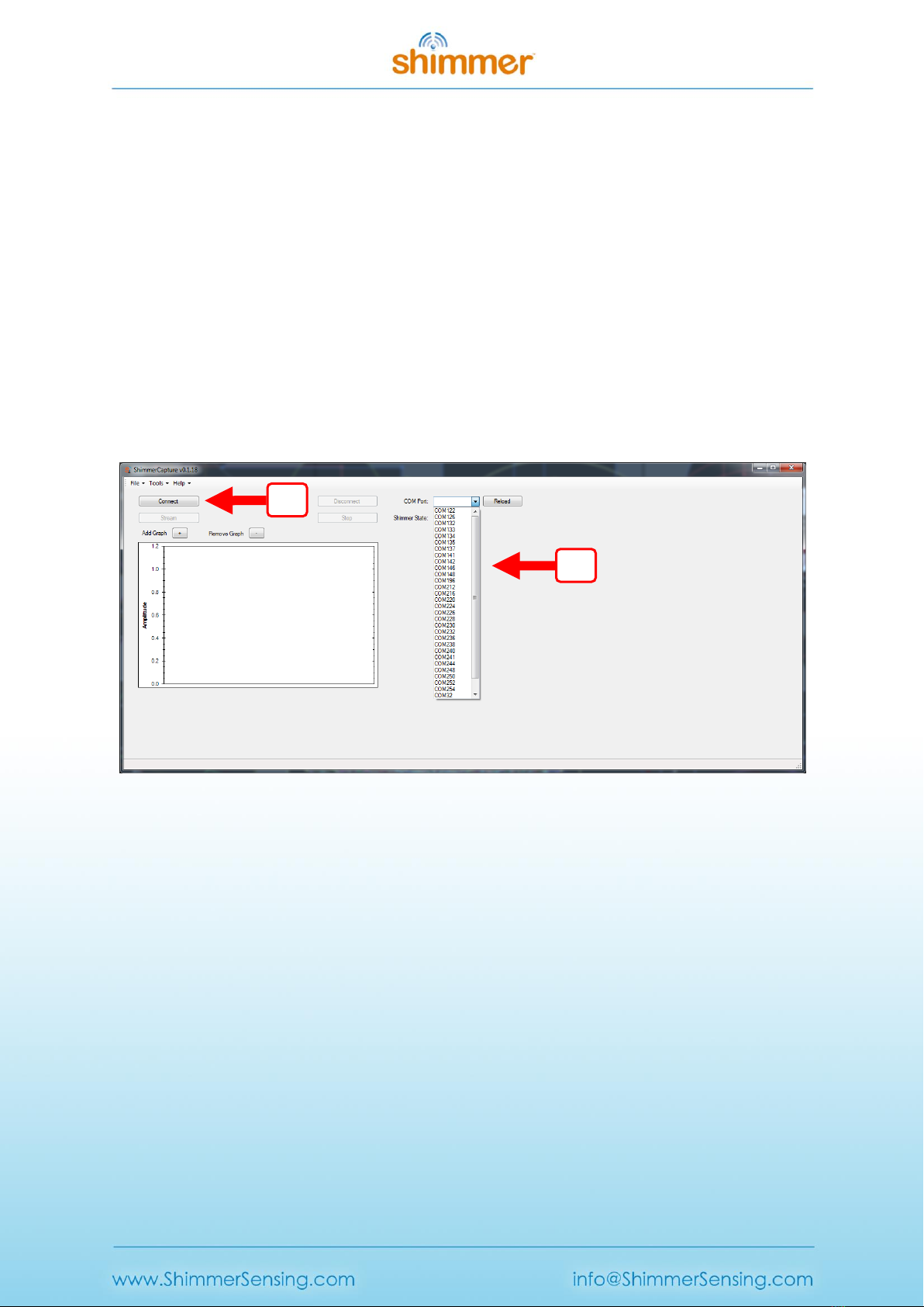
2.2. Connecting to a Shimmer
The Bluetooth serial port for the desired Shimmer3, as assigned during the pairing procedure, must
be selected (for details on pairing a Shimmer device please refer to the Shimmer User Manual). This
can be selected using the drop down menu, or by typing the value in manually. In Windows this will
be in the form of “COM<nn>”. See Shimmer User Manual for more details.
Figure 2-1 Selecting the COM port. Step 1 - Select the correct COM port, Step 2 - press the "Connect"
button.
Once the correct serial port is selected, press the “Connect” button. While the ShimmerCapture
application is connecting to the Shimmer3, the status bar of the application will indicate the stage of
the connection sequence, as shown in Figure 2-2.
1
2
Copyright © Shimmer 2014
Realtime Technologies Ltd ShimmerCapture User Manual
All rights reserved Rev 0.5a
7
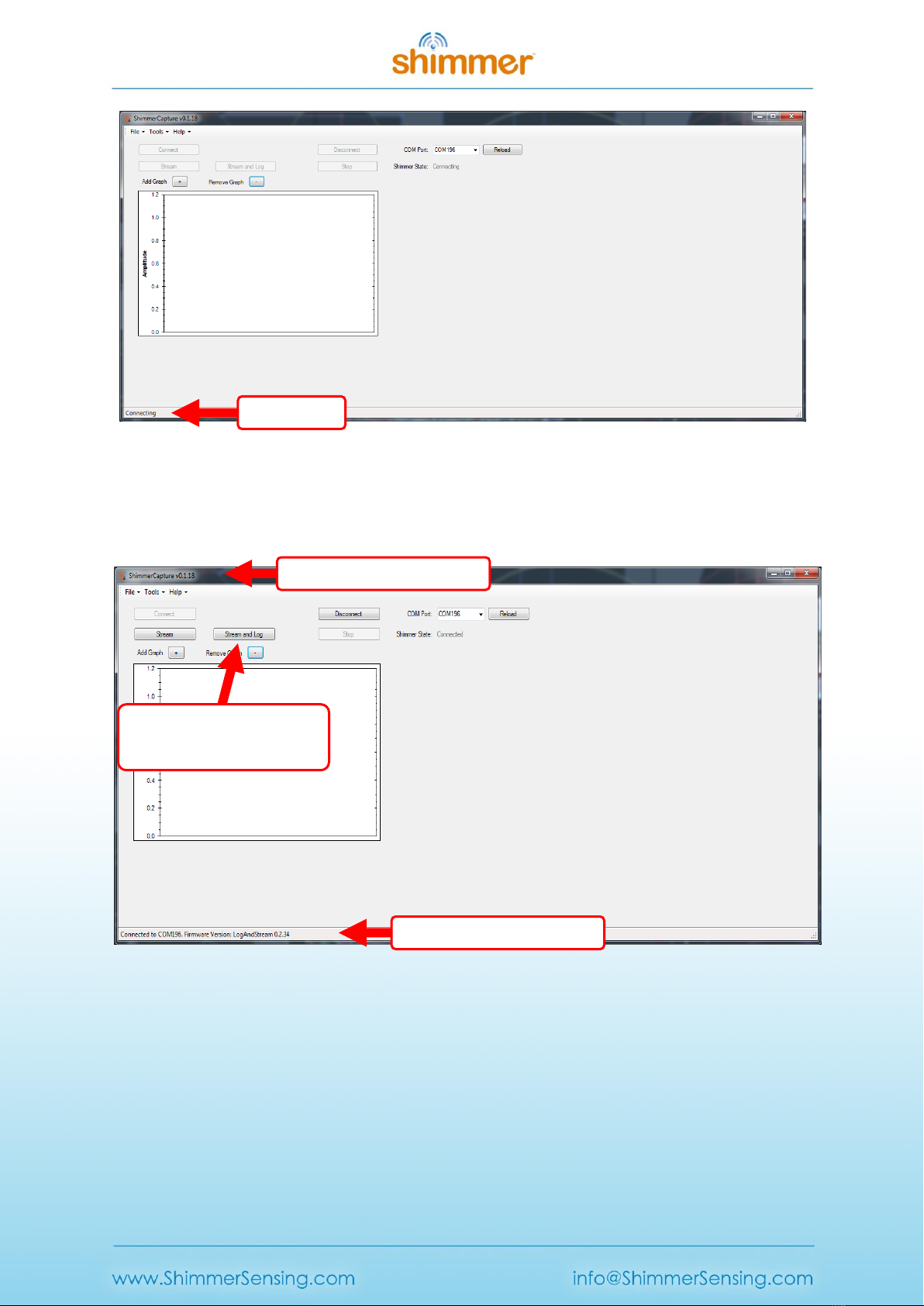
Figure 2-2 ShimmerCapture in the process of connecting.
Once connected the other buttons on the Control window will be enabled and the status bar at the
bottom will be updated. The blue LED on the Shimmer will also illuminate to indicate connection
status.
Figure 2-3 ShimmerCapture display once connected.
An important feature to note in ShimmerCapture can be seen in Figure 2-3. Similar to previous
Shimmer Bluetooth streaming solutions, the "Stream" button enables streaming of data over the
Bluetooth connection. However, a new feature of ShimmerCapture is the ability to simultaneously
stream data over Bluetooth at the same time as logging to the on-board microSD card - which can be
enabled by pressing the "Log+Stream" button. In both cases, the data can also be logged locally to
the PC by selecting the appropriate option (Save to CSV) from the "Tools" menu.
Shimmer firmware version
ShimmerCapture version
Status bar
Simultaneous Logging and
Streaming feature
Copyright © Shimmer 2014
Realtime Technologies Ltd ShimmerCapture User Manual
All rights reserved Rev 0.5a
8
While the Shimmer3 device (programmed with LogAndStream firmware) is logging to the on-board
microSD card, a Bluetooth connection can be established or disconnected at any time without
interrupting the SD logging operation.
2.3. Configuring the Shimmer
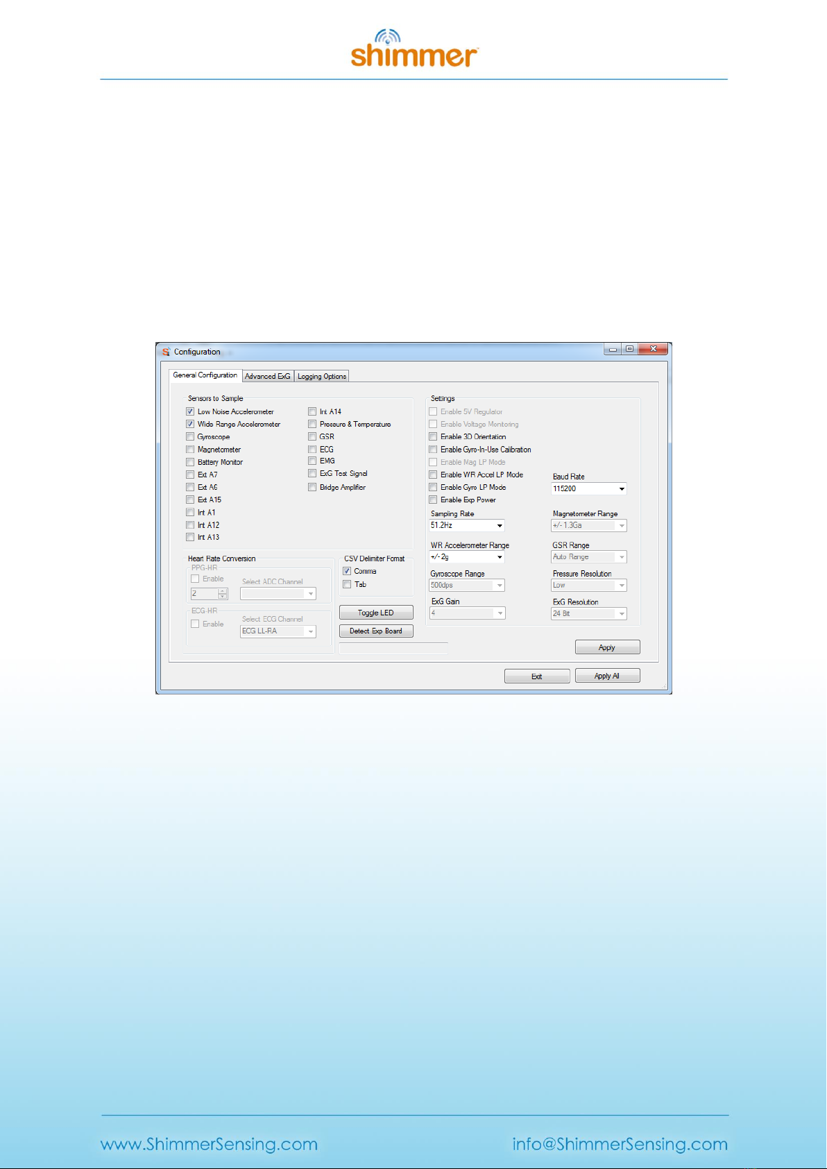
2.3.1. Configuration Window
Once ShimmerCapture is connected to the Shimmer3, it reads the current configuration saved on the
Shimmer3. To view or change this configuration select Tools -> Configuration. This will bring up the
general configuration window, as shown in Figure 2-4.
Figure 2-4 Configuring a Shimmer3 with programmed LogAndStream firmware.
Other than the “Toggle LED” command, no changes made in this window will be reflected on the
Shimmer3 until the “Apply”or “Apply All” button is pressed. The “Cancel” button will cancel any
changes made since opening this window, other than the effect of the “Toggle LED” command.
Note: The configuration panel settings cannot be changed while the Shimmer3 is in the
process of streaming data.
Sampling Rate:
This can be modified by selecting a different rate from the drop down menu.
Note: In the ShimmerCapture application, the sampling rate must be chosen from the
dropdown box. If the user types in a value other than those listed in the dropdown box this
value will be ignored during configuration.

Copyright © Shimmer 2014
Realtime Technologies Ltd ShimmerCapture User Manual
All rights reserved Rev 0.5a
9
Toggle LED:
Pressing this button immediately toggles the red LED on the Shimmer.
Sensors to sample:
The sensors of interest can be selected here. In the configuration window, the Shimmer3's
accelerometers are labelled as LNAccelerometer (Low Noise Accelerometer) and
WRAccelerometer (Wide Range Accelerometer). The LNAccelerometer is an Analog
accelerometer (KXRB5-2042) which has a single range (± 2 g). The WRAccelerometer is a
digital accelerometer (LSM303DLHC) which has four different ranges (± 2 g, ± 4 g, ± 8 g and
± 16 g). The LNAccelerometer has lower noise levels when compared to the
WRAccelerometer.
The Shimmer3 also includes a Pressure sensor (BMP180). The pressure sensor's resolution is
configurable (ultra low power, standard, high resolution and ultra high resolution). Users
should take note of the maximum sampling rate of the BMP180 when selecting the
Shimmer3 sampling rate and the resolution mode - further details can be found in the
BMP180 data sheet. Enabling the pressure sensor also enables the BMP180's temperature
sensor channel.
In order to obtain meaningful data from the GSR and ExG (ECG or EMG) channels, the
appropriate sensor module must be attached to the Shimmer3. The GSR and ExG sensors
channels cannot be selected simultaneously as the Shimmer3's internal connector can only
be connected to one of the corresponding expansion boards at the time.
Enable 3D Orientation:
This will enable the Accelerometer, Gyroscope and Magnetometer, the orientation of the
Shimmer3 device in terms of Quaternions will now be calculated and displayed when the
user starts streaming again. Users should note that for best results, the Shimmer3 device
should be pre-calibrated using the Shimmer 9DoF Calibration application which is available
for download from the Members area at www.shimmersensing.com.
Enable Gyro-On-The-Fly Calibration:
This will enable the calibration of the gyroscope while the Shimmer device is streaming.
When enabled, the offset vector of the Gyroscope is recalculated when the Shimmer device
is found to be stationary. Implementation details can be found in the ShimmerCapture
source code.
Enable Low Power Magnetometer:
There are seven sampling rates for the Shimmer3 (0.75 Hz, 1.5 Hz, 3 Hz, 7.5 Hz, 15 Hz, 30 Hz,
75 Hz, 220 Hz). The Magnetometer sampling rate is set to 15 Hz (Shimmer3) when low
power magnetometer is enabled, otherwise the sampling rate of the Magnetometer is set as
close as possible to the current sampling rate of the Shimmer3 device.

Copyright © Shimmer 2014
Realtime Technologies Ltd ShimmerCapture User Manual
All rights reserved Rev 0.5a
10
Enable Low Power Accelerometer:
When low power mode is enabled, the sampling rate of the WRAccelerometer
(LSM303DLHC) is set to 10 Hz. This low power mode will only be usable when the "WRAccel
Range" is selected to be between ± 4 g and ± 16 g.
Enable Internal Exp Power:
This option is used to power-on a module or expansion board connected to the Shimmer3.
WRAccel Range:
This field selects the accelerometer range using a drop down menu. The Shimmer3 features
a digital accelerometer (WRAccelerometer) which has a user selectable range of ± 2 g, ± 4 g,
± 8 g or ± 16 g. This field is greyed out and not configurable if the WRAccelerometer sensor is
not selected.
Enable Low Power Gyroscope:
When low power mode is enabled, the sampling rate of the Shimmer3's gyroscope is set to
31.25 Hz.
Gyro Range:
This field selects the gyroscope range using a drop down menu. The gyroscope on the
Shimmer3 four selectable ranges: 250 dps, 500 dps, 1000 dps and 2000 dps.
Pressure Resolution:
This field is used to set the resolution level of the Pressure sensor on the Shimmer3.
GSR Range:
This field selects the range of the GSR sensor using a drop down menu. When set to Auto-
Range, the most suitable range for the current reading is selected by the shimmer itself. This
field is greyed out and not configurable if the GSR sensor is not selected.
ExG Resolution:
Setting determines whether ECG/EMG data will be sent in 16-bit or 24-bit format. Users
should note that 24-bit is the default format provided by the chips on the ExG Expansion
Board and, if 16-bit data is selected, the 7 least significant bits and the 1 most significant bit
of the ECG/EMG samples will be discarded by the firmware before transmitting the data
over Bluetooth. In the instrument driver, the calibration procedure handles the different
data types.
ExG Gain:
Setting determines the software configurable gain of the ExG channels. The recommended
value for ECG or EMG data collection will be automatically chosen when the ECG or EMG

Copyright © Shimmer 2014
Realtime Technologies Ltd ShimmerCapture User Manual
All rights reserved Rev 0.5a
11
sensor, respectively, is enabled. Please refer to the Shimmer ExG User Guide for ECG or the
Shimmer ExG User Guide for EMG for more details.
Baud Rate:
This field selects the baud rate of the Bluetooth module on the Shimmer3. Setting the baud
rate to a higher value should allow streaming of more channels at a higher data rates while
reducing packet loss. Note: In order to change the baud rate of the Shimmer3, the
Shimmer3 must disconnect, and then reconnect with the ShimmerCapture application. The
ShimmerCapture application automatically handles this disconnect/connect cycle but
sometimes fails when trying to reconnect with the Shimmer device. If this occurs, please
reconnect with the Shimmer as described in section 2.2.
Detect Expansion:
Pressing this button lets the user know which expansion board (if any) is attached to the
Shimmer3.
Logging Delimiter Format:
This field specifies the file delimiter (comma or tab) when logging data to the csv file on the
computer.
SD Logging Parameters:
Figure 2-5 Configuring logging options for Shimmer3 with programmed LogAndStream firmware.
Shimmer Name: Used to give an appropriate name to the Shimmer unit. The entry is limited
to 11 characters. If the field is left empty, the name will default to "idXXXX" where XXXX is
the Bluetooth ID number specific to the Shimmer.

Copyright © Shimmer 2014
Realtime Technologies Ltd ShimmerCapture User Manual
All rights reserved Rev 0.5a
12
Experiment ID: Used to give an appropriate name to the current trial in the Shimmer unit.
The entry is limited to 11 characters and has a default value of “default_exp”.
Trigger Mode:
The trigger mode allows the user to select how they wish to start and end data logging. The
two available options are Undock Start and Push Button Start. The Push Button Start option
is reliant on the Shimmer3's dedicated user button which is orange in colour and located
beside the two LEDs. In ShimmerCapture, the default option is Push Button Start.
Undock start:
If enabled, the following process begins when the Shimmer is removed from the dock.
1. The Shimmer unit will go into standby mode for up to 3 seconds.
2. The Shimmer unit will read the configuration file and create the required
directories on the SD card.
3. The Shimmer unit will start SD logging.
SD logging will continue until the Shimmer unit is reset, powered off, replaced in the
dock or the battery runs out, whichever happens soonest. Alternatively, once connected
over Bluetooth through ShimmerCapture, pressing the "Stop" button on the
ShimmerCapture control panel will also halt SD logging.
Repeatedly resetting the Shimmer unit will result in multiple logging sessions on the SD
card.
Note: If using the Undock Start option, you must log for data for at least one minute to
ensure data is successfully written to the SD card.
Push Button Start:
If enabled, undocking the Shimmer unit or powering it on and off, the dock will trigger
the same steps 1 and 2 as above (i.e., standby for 3 seconds followed by configuration).
However, SD logging will not start until either the push button on the Shimmer3 unit or
the "Log+Stream" button in the ShimmerCapture Control panel is pressed. SD Data
logging ends when the Shimmer3's push button is pressed again or when the Shimmer
unit is reinserted into the dock. Enabling this option makes Push Button Select option
enabled and available for selection.
Note: For more detailed information on the operation of the Trigger Mode options, consult
the LogAndStream for Shimmer3 Firmware User Manual.
2.3.2. Configuring with/without the Shimmer Dock
A Shimmer3 (programmed with LogAndStream firmware) can be configured through
ShimmerCapture either with the Shimmer3 placed on the Shimmer Dock or with it in an undocked

Copyright © Shimmer 2014
Realtime Technologies Ltd ShimmerCapture User Manual
All rights reserved Rev 0.5a
13
state. In both cases, ShimmerCapture will attempt to send the configuration information to the
Shimmer3 Infomem (i.e., a region of EEPROM memory in the Shimmer's microcontroller).
It is important to note that, on power-cycle or device reset, the LogAndStream firmware will attempt
to load the last configuration parameters saved to the Infomem. Failing this scenario, default
configuration values will be loaded. For more detailed information on the operation the
configuration file and Infomem , consult the LogAndStream Firmware User Manual.
Undocked
When the Shimmer3 is undocked, the configuration parameters are sent from the ShimmerCapture
application to the Shimmer3 where the firmware will automatically store the settings in Infomem. It
will also attempt to create (or overwrite) the configuration file on the microSD card.
Docked
In the docked state, as before, the Shimmer3 will save the configuration parameters to the Infomem.
Once undocked the firmware will attempt to create (or overwrite) the configuration file on the
microSD card
Note: A Shimmer3 programmed with LogAndStream firmware should not be configured
while it is placed on a Shimmer Multi Charger. In this state, the Shimmer3 thinks that it is
connected to a Shimmer Dock and will surrender control of the microSD card. The settings
will not be written to the configuration file and on next power-cycle or device reset, the
settings in Infomem will be overwritten with old configuration parameters.
Note: It is not recommended to dock the Shimmer unit while it is being configured or logging
data. The Shimmer unit should either be powered off or in standby mode whenever it is
docked.
2.4. Configuring a Shimmer GSR+ Expansion Board
An external sensor option for the Shimmer3 is the Shimmer GSR+ Expansion Board. Among other
capabilities, this can be used to interface a PPG (Photoplethysmography) sensor to a Shimmer3
device. To use PPG, the following must be enabled
Int ADC A13 - The output of the sensor connected to the GSR+ Expansion Board is measured
by the internal ADC A13
Internal Exp Power (to power the external sensor e.g. PPG)
PPG data output will be under the category 'Internal ADC A13'. For further functionality information
of the GSR+ Expansion Board, users are encouraged to read the GSR+ Expansion Board User Guide.
When using PPG users can use the PPG to HR algorithm to convert the PPG signal into Heart Rate
(BPM). Snapshot of the dialog box within the configuration panel is as shown:-

Copyright © Shimmer 2014
Realtime Technologies Ltd ShimmerCapture User Manual
All rights reserved Rev 0.5a
14
The numerical combo box allows users to select the window size of the buffer to average over when
calculating Heart Rate.
2.5. Configuring a Shimmer ExG Module
The "Advanced ExG" tab in the "Tools -> Configuration" menu allows users to configure a ExG
Expansion Board.
Selecting "Advanced ExG" tab will open and ExG configuration form as shown below.
Figure 2-6 ExG Configuration window.
A selection of ExG filtering options are also provided in the “Advanced ExG” tab. If filtering is
enabled, the raw and calibrated data will be filtered. Users should note that not all sampling
frequencies are supported by the filters. For unsupported frequencies, with filtering enabled, the
data remains unfiltered. For the high-pass filters, frequency rates of 51.2 Hz, 102.4 Hz, 204.8 Hz,
250.1 Hz, 512 Hz and 1024 Hz are supported. For the band-stop filters, frequency rates of 250.1 Hz,
512 Hz and 1024 Hz are supported. These filters are 2nd order Butterworth filters whose coefficients

Copyright © Shimmer 2014
Realtime Technologies Ltd ShimmerCapture User Manual
All rights reserved Rev 0.5a
15
can be found online
4
. Users should note that these filters are used as examples and that, depending
on use case and application, other filtering options might perform better.
There are three default settings that are available for selection: Default ECG, Default EMG and
Default ExG Test. For example, checking the "Default ECG" checkbox will update the 20 registers (i.e.,
10 register bytes for each ExG chip) on the user interface with the recommended default settings for
ECG. Note that the register values in the user interface is only sent to the Shimmer3 when the
“Apply” or “Apply All” button is pressed. Updating the ExG gain settings will also update the registers
in the GUI.
ExG Reference Electrode:
Setting determines whether the reference voltage used in the ExG amplifiers is a fixed
reference voltage generated by the chip or taken from a feedback channel on the body.
Please refer to the Shimmer ExG User Guide for ECG or the Shimmer ExG User Guide for EMG
for more details.
ExG Lead-Off Detection, ExG Lead-Off Current, ExG Lead-Off Comparator Threshold:
The ExG Lead-Off settings are used to enable lead-off detection mode for the Shimmer3 and
to choose the parameters for lead-off detection, such as the current applied to the body and
the threshold levels.
The user can also choose to configure their ExG unit using a custom configuration by entering their
desired configuration into the numeric text boxes list to the right of the "Chip 1" and "Chip 2" labels.
The following are the 10 register bytes name and description. More detailed information on the ExG
configuration bytes can be found within the ExG User Guide for ECG / ExG User Guide for EMG.
Byte Position
Name
Description
Byte 0
CONFIG1:
Configuration Register 1
This register configures each ADC channel
sample rate.
Byte 1
CONFIG2:
Configuration Register 2
This register configures the test signal, clock,
reference, and LOFF buffer.
Byte 2
LOFF:
Lead-Off Control Register
This register configures the lead-off detection
operation.
Byte 3
CH1SET:
Channel 1 Settings
This register configures the power mode, PGA
gain and multiplexer settings channels.
Byte 4
CH2SET:
Channel 2 Settings
This register configures the power mode, PGA
gain and multiplexer settings channels.
Byte 5
RLD_SENS:
Right Leg Drive Sense Selection
This register configures the selection of the
positive and negative signals from each channel
for the right leg drive derivation.
Byte 6
LOFF_SENS:
Lead-Off Sense Selection
This register selects the positive and negative
side from each channel for lead-off detection.
4
http://www-users.cs.york.ac.uk/~fisher/mkfilter/trad.html

Copyright © Shimmer 2014
Realtime Technologies Ltd ShimmerCapture User Manual
All rights reserved Rev 0.5a
16
Byte 7
LOFF_STAT:
Lead-Off Status
The register stores the status of whether the
positive or negative electrode on each channel is
on or off.
Byte 8
RESP1:
Respiration Control Register 1
This register controls the respiration
functionality.
Byte 9
RESP2:
Respiration Control Register 2
This register controls the respiration and
calibration functionality.
Table 2-1 ExG Configuration Bytes Contents
ShimmerCapture provides a brief illustration of how the ExG lead off functionality can be used to
detect whether all ECG leads are connected to the ExG board. See the following steps for illustration.
1. Enable the Default ECG checkbox, set the ExG Lead-Off Detection to DC Current as in Figure
2-7 and press the “Apply All” button.
Figure 2-7 Advanced ExG tab for ECG lead off detection
2. Press the “Start”button to begin streaming the ECG signal and observer the “ExG Lead-Off
Detection”checkboxes.
Default ECG checkbox
ExG lead off detection
Copyright © Shimmer 2014
Realtime Technologies Ltd ShimmerCapture User Manual
All rights reserved Rev 0.5a
17
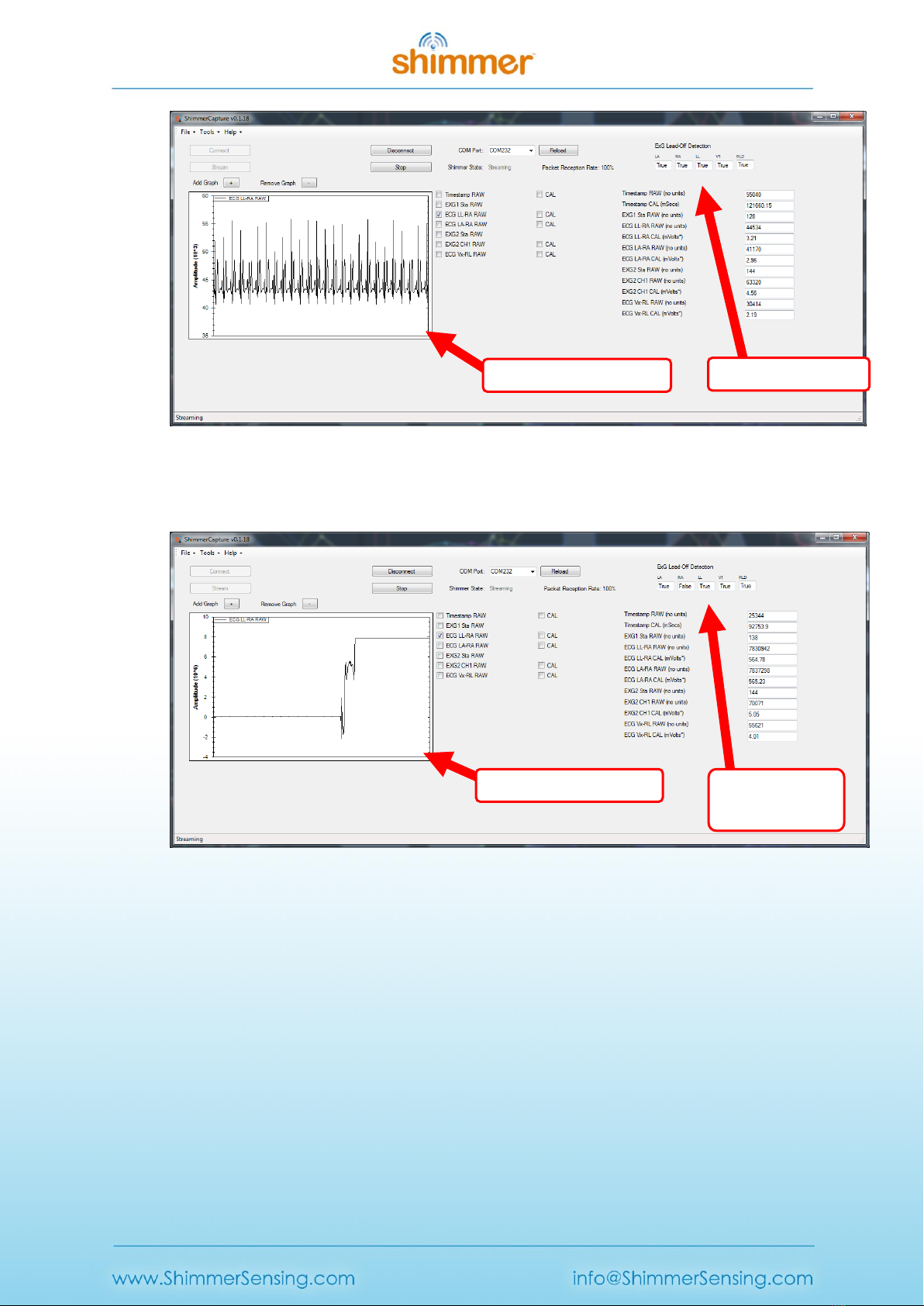
Figure 2-8 Streaming ECG signal with all leads connected
3. Remove one of the ECG leads and observe the “ExG Lead-Off Detection” checkboxes.
Figure 2-9 Streaming ECG signal with RA lead disconnected
All leads connected
One lead, “RA”
disconnected
Poor quality ECG signal
High quality ECG signal

Copyright © Shimmer 2014
Realtime Technologies Ltd ShimmerCapture User Manual
All rights reserved Rev 0.5a
18
When using ECG users can use the ECG to HR algorithm to convert the ECG signal into Heart Rate
(BPM). Snapshot of the dialog box within the configuration panel is as shown:-
The numerical combo box allows users to select the window size of the buffer to average over when
calculating Heart Rate.
2.6. Streaming Data
To stream data from the Shimmer3, press either of the “Stream only” or “Log+Stream” buttons on
the ShimmerCapture control panel. Alternatively, if "Push Button Start" is enabled from the “Logging
Options” configuration window, pressing the push button on the Shimmer3 device will automatically
start "Log+Stream" operations. To stop steaming and logging data, either press the "Stop" streaming
button on the control panel or press the push button on the Shimmer3 device. To stop streaming but
continue logging, press the "Disconnect" button on the control panel.
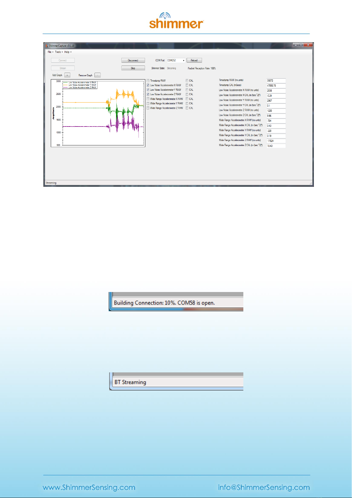
The following screen shot shows a Shimmer streaming seven channels of data. The labels above the
text boxes and on the graph windows show indicate the source of each channel..
Note: It is a known issue, that on rare occasions the parsing of the streamed data for LogAndStream
firmware can be incorrect when a large number of channels are enabled with one of the ExG
channels (ECG, EMG, ExG Test Signal). While Shimmer will make every effort to resolve this bug in a
future release, users are reminded that ShimmerCapture is not intended to be the answer to all host
side application requirements but instead as a quick start application which for many users can act
as a stepping stone for more advance Shimmer applications. If a user does experience this bug,
usually reducing the number of the channels the Shimmer is streaming eliminates the problem.
Copyright © Shimmer 2014
Realtime Technologies Ltd ShimmerCapture User Manual
All rights reserved Rev 0.5a
19
Figure 2-10 Streaming Data.
2.7. Status bar
The ShimmerCapture status bar provides a useful source of feedback for the state of the Shimmer3
device and the LogAndStream firmware.
Connecting:
While ShimmerCapture is connecting the Shimmer3, the status bar is continually updated with the
current step in the Bluetooth connection sequence.
Figure 2-11 Status bar during Bluetooth connecting.
Bluetooth Streaming
After the "Stream only" button has been pressed, the status bar will change to "BT Streaming", as
below:
Figure 2-12 Status bar during Bluetooth Streaming only operation.
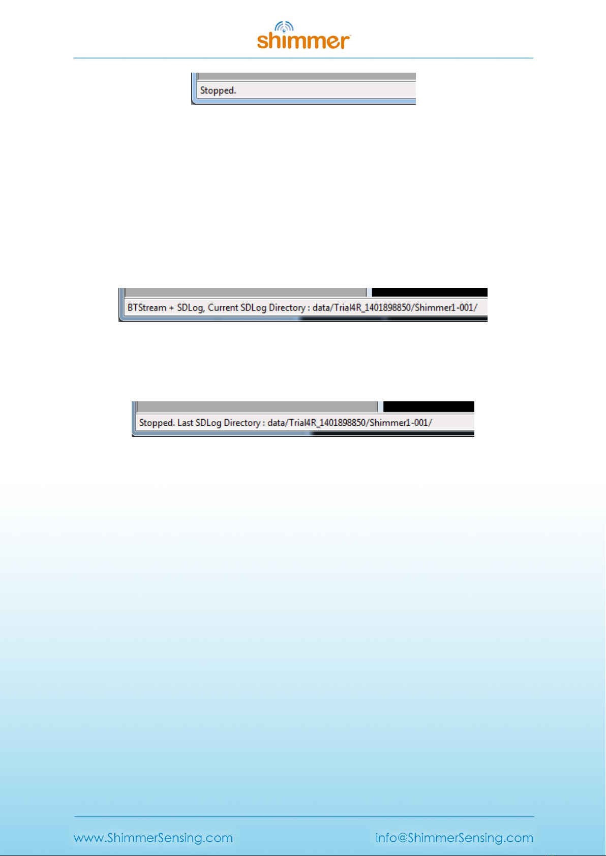
Once the "Stop" button is pressed from the "Stream only" mode, the following status bar text will
appear:
Copyright © Shimmer 2014
Realtime Technologies Ltd ShimmerCapture User Manual
All rights reserved Rev 0.5a
20
Figure 2-13 Status bar after Bluetooth streaming only operation.
Logging and Bluetooth Streaming
When the "Log+Stream" button is pressed, the status bar will show the "BTStream + SDLog" label. In
addition to this, the current logging directory on the microSD card will also be listed. The name of
the current directory is based on the configuration parameters set in the configuration window - in
this case as those listed in Figure 2-4. In this example, the status bar lists the: trial name (i.e.,
"Trial4R"), configuration time (i.e., "1401898850"), device name (i.e., "Shimmer1") and folder
increment number (i.e., "001"). More information on the representation of the configuration time
can be found in the ShimmerLog User Manual.
Figure 2-14 An example status bar message during Bluetooth streaming and SD logging.
Once the "Stop" button is pressed from the "Log+Stream" mode, the status bar will show the
"Stopped" label as well as the last SD logging directory, as below:
Figure 2-15 An example status bar message after the "Stop" button has been pressed on the control
panel.
2.8. Disconnecting from a Shimmer
The “Disconnect” button in the Control window disconnects ShimmerCapture from the Shimmer.
From "Stream only" mode this will halt all activity on the Shimmer3 and it will return to idle mode
waiting for user input. From "Log+Stream" mode, the Bluetooth link will disconnect but the logging
of data to the SD will continue uninterrupted. Whilst the Shimmer3 is logging, the user can choose to
reconnect over Bluetooth at any stage and this will not interfere with the SD logging operation.
2.9. Saving data to a local file
The data being received by ShimmerCapture can be saved to a local file on the PC in a comma
separated value format (CSV). This facility can be enabled by selecting Tools → Save To CSV. A tick
mark will appear next to this item in the Tools menu when the data is being saved to file. Both raw
and calibrated data will be logged to the file. An option to save the data in a tab delimited format
can be found on the configuration window.
Selecting the "Save To CSV" option opens a new window asking for the name and location of the file
to be used. The name defaults to “ShimmerData.csv” and the location defaults to the user’s home
Table of contents
Other Shimmer Medical Equipment manuals


Popular Medical Equipment manuals by other brands


VNS Therapy
VNS Therapy LivaNova Tunneler 402 Directions for use

Eyecon
Eyecon 9420 instruction manual

Brillinger
Brillinger COMFORT elbow support plus Instructions for use

Plinth 2000
Plinth 2000 93CDT Service manual

Kora
Kora 353 user manual

Invacare
Invacare Alternating Pressure Air Mattress MNS400-B Specification sheet