Thermo Forma 3033 Operating instructions

Artisan Technology Group is your source for quality
new and certied-used/pre-owned equipment
• FAST SHIPPING AND
DELIVERY
• TENS OF THOUSANDS OF
IN-STOCK ITEMS
• EQUIPMENT DEMOS
• HUNDREDS OF
MANUFACTURERS
SUPPORTED
• LEASING/MONTHLY
RENTALS
• ITAR CERTIFIED
SECURE ASSET SOLUTIONS
SERVICE CENTER REPAIRS
Experienced engineers and technicians on staff
at our full-service, in-house repair center
WE BUY USED EQUIPMENT
Sell your excess, underutilized, and idle used equipment
We also offer credit for buy-backs and trade-ins
www.artisantg.com/WeBuyEquipment
REMOTE INSPECTION
Remotely inspect equipment before purchasing with
our interactive website at www.instraview.com
LOOKING FOR MORE INFORMATION?
Visit us on the web at www.artisantg.com for more
information on price quotations, drivers, technical
specications, manuals, and documentation
Contact us: (888) 88-SOURCE | sales@artisantg.com | www.artisantg.com
SM
View
Instra

Models:
3033 and 3035
3860 and 3862
Steri-Cult Incubators
Operating and Maintenance Manual
Manual No: 7073033 Rev. 6
Artisan Technology Group - Quality Instrumentation ... Guaranteed | (888) 88-SOURCE | www.artisantg.com

Model 3033 and 3860 Series ________________________________________________________________________
i
Read This Instruction Manual.
Failure to read, understand and follow the instructions in
this manual may result in damage to the unit, injury to operat-
ing personnel, and poor equipment performance.
CAUTION! All internal adjustments and maintenance must
be performed by qualified service personnel.
Refer to the serial tag on the back of this manual.
The material in this manual is for information purposes only.
The contents and the product it describes are subject to change
without notice. Thermo Forma makes no representations or war-
ranties with respect to this manual. In no event shall Thermo
Forma be held liable for any damages, direct or incidental, aris-
ing out of or related to the use of this manual.
MANUAL NUMBER 7073033
6 20122/IN-2948 6/18/01 Updated electrical schematics to meet EMC standards ccs
5 Updates from 2 4/16/01 Updated Accessories list (caster dollies) ccs
4 19588/SI-8132 12/21/00 Changed power switch P/N 360146 to 363033 (elec. schematics) aks
3 -- 5/19/00 Quark format ccs
2 18501/SI-7634 8/17/99 Added securing bracket in Section 2 ccs
REV ECR/ECN DATE DESCRIPTION By
Contains Parts and Assemblies
Susceptible to Damage by
Electrostatic Discharge (ESD)
CAUTION
Artisan Technology Group - Quality Instrumentation ... Guaranteed | (888) 88-SOURCE | www.artisantg.com

Model 3033 and 3860 Series ________________________________________________________________________
ii
Important operating and/or maintenance instructions. Read the accompanying text carefully.
Ce symbole attire l'attention de l'utilisateur sur des instructions importantes de fonctionnement et/ou d'entretien. Il
peut être utilisé seul ou avec d'autres symboles de sécurité. Lire attentivement le texte d'accompagnement.
Wichtige Betriebs- und/oder Wartungshinweise. Lesen Sie den nachfolgenden Text sorgfältig.
Importante instruccions de operacion y/o mantenimiento. Lea el texto acompanante cuidadosamente.
Potential electrical hazards. Only qualified persons should perform procedures associated with this symbol.
Ce symbole attire l'attention de l'utilisateur sur des risques électriques potentiels. Seules des personnes qualifiées
doivent appliquer les instructions et les procédures associées à ce symbole.
Gefahr von Stromschlägen. Nur qualifizierte Personen sollten die Tätigkeiten ausführen, die mit diesem Symbol beze-
ichnet sind.
Potencial de riesgos electricos. Solo personas das capacitadadas deben ejecutar los procedimientos asociadas con este
simbulo.
Equipment being maintained or serviced must be turned off and locked off to prevent possible injury.
Risques potentiels liés à l'énergie. L'équipement en entretien ou en maintenance doit être éteint et mis sous clé pour
éviter des blessures possibles.
Geräte, an denen Wartungs- oder Servicearbeiten durchgeführt werden, müssen abgeschaltet und abgeschlossen wer-
den, um Verletzungen zu vermeiden.
El equipo recibiendo servicio o mantenimiento debe ser apagado y segurado para prevenir danos.
!""""Always use the proper protective equipment (clothing, gloves, goggles, etc.)
!"""Always dissipate extreme cold or heat and wear protective clothing.
!"""Always follow good hygiene practices.
!"""Each individual is responsible for his or her own safety.
Artisan Technology Group - Quality Instrumentation ... Guaranteed | (888) 88-SOURCE | www.artisantg.com

Model 3033 and 3860 Series ________________________________________________________________________
Artisan Technology Group - Quality Instrumentation ... Guaranteed | (888) 88-SOURCE | www.artisantg.com

Artisan Technology Group - Quality Instrumentation ... Guaranteed | (888) 88-SOURCE | www.artisantg.com

Model 3033 and 3860 Series ______________________________________________________________Table of Contents
iv
Table of Contents
Section 1 - Receiving . . . . . . . . . . . . . . . . . . . . . . . . . . .2 - 1
1.1 Preliminary Inspection . . . . . . . . . . . . . . . . . . . . . .2 - 1
1.2 Visible Loss or Damage . . . . . . . . . . . . . . . . . . . . .2 - 1
1.3 Responsibility for Shipping Damage . . . . . . . . . . .2 - 1
Section 2 - Installation and Start-up . . . . . . . . . . . . . .2 - 1
2.1 Location . . . . . . . . . . . . . . . . . . . . . . . . . . . . . . . . .2 - 1
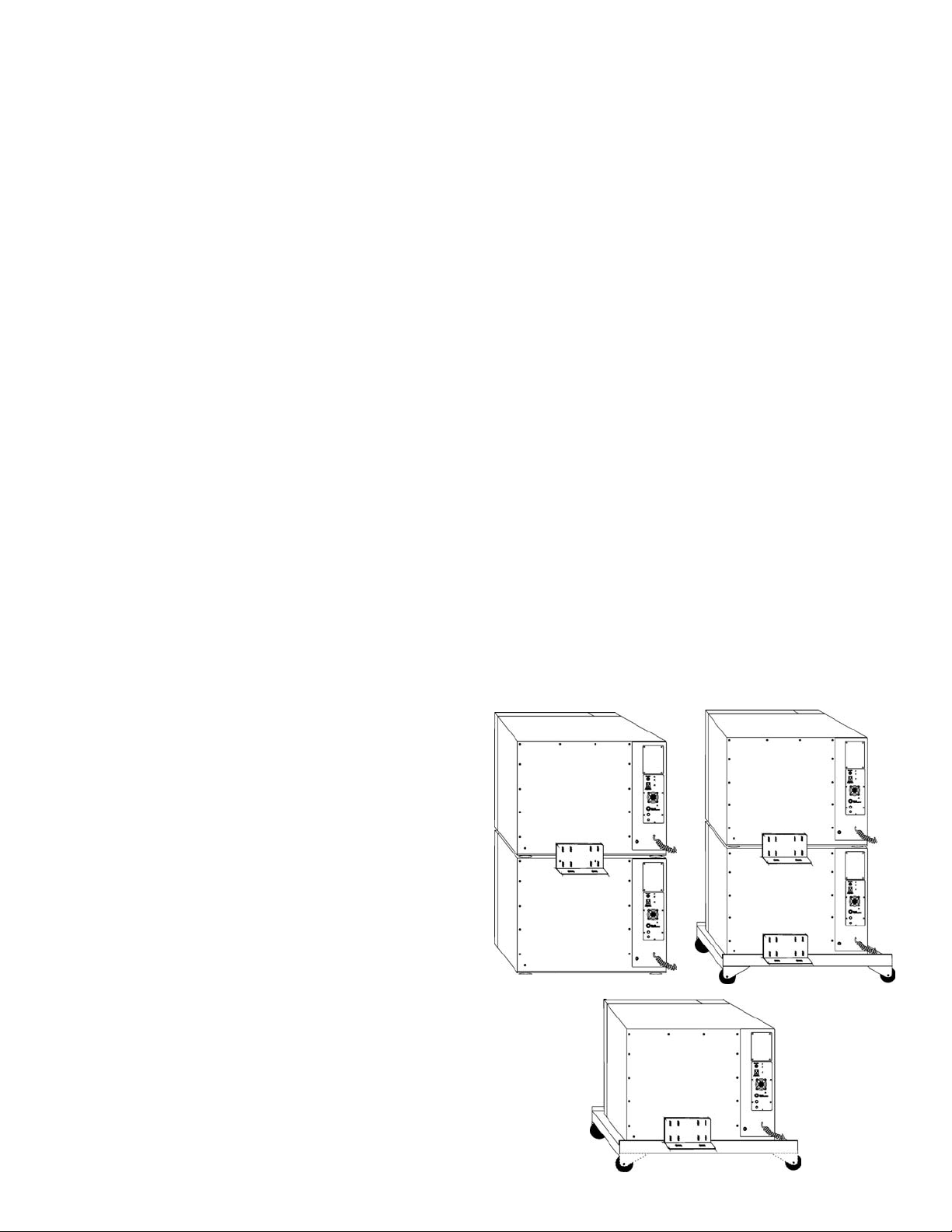
2.2 Securing the Unit . . . . . . . . . . . . . . . . . . . . . . . . . .2 - 1
2.3 Leveling . . . . . . . . . . . . . . . . . . . . . . . . . . . . . . . . .2 - 2
2.4 Connecting to Power . . . . . . . . . . . . . . . . . . . . . . . .2 - 2
2.5 Connecting the Water Drain Line . . . . . . . . . . . . . .2 - 2
2.6 Preliminary Disinfecting . . . . . . . . . . . . . . . . . . . . .2 - 2
2.7 Installing the Diffuser Pans and Pilasters . . . . . . . . .2 - 2
2.8 Installing the Shelves . . . . . . . . . . . . . . . . . . . . . . .2 - 2
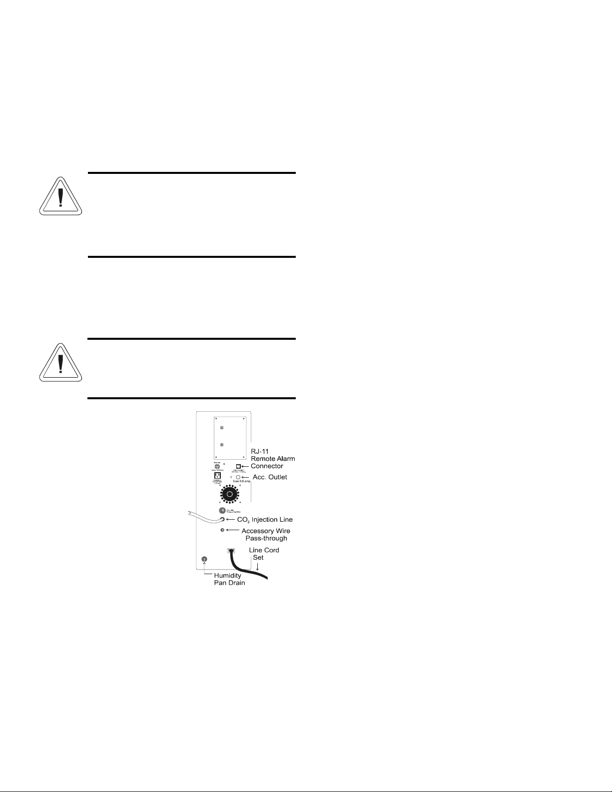
2.9 Connecting the CO2 Supply . . . . . . . . . . . . . . . . . .2 - 3
a. To connect the CO2 supply: . . . . . . . . . . . . . . . .2 - 3
2.10 Connecting the Temp/Alarm Back-Up Battery . . .2 - 3
2.11 Filling the Humidity Reservoir . . . . . . . . . . . . . . .2 - 4
2.12 Setting the Over/Under Temperature Safety . . . . . .2 - 4
2.13 Setting the CO2 . . . . . . . . . . . . . . . . . . . . . . . . . . .2 - 5
2.14 Setting the Relative Humidity . . . . . . . . . . . . . . . .2 - 5
2.15 Setting the Chamber Temperature . . . . . . . . . . . . . .2 - 5
2.16 Connecting to the Recorder Jack . . . . . . . . . . . . . .2 - 5
2.17 Connecting to the Remote Alarm Contacts . . . . . . .2 - 6
2.18 Convenience/Accessory Outlet . . . . . . . . . . . . . . . .2 - 6
Section 3 - Operation . . . . . . . . . . . . . . . . . . . . . . . . .3 - 1
3.1 Description . . . . . . . . . . . . . . . . . . . . . . . . . . . . . . .3 - 1
3.2 Power Control Panel . . . . . . . . . . . . . . . . . . . . . . . . .3 - 1
a. Main Power Switch . . . . . . . . . . . . . . . . . . . . . .3 - 1
b. Program/Run Key Switch . . . . . . . . . . . . . . . . .3 - 1
c. Door Ajar Light . . . . . . . . . . . . . . . . . . . . . . . . .3 - 1
d. Sample Port . . . . . . . . . . . . . . . . . . . . . . . . . . . .3 - 1
3.3 Temperature Alarm/Monitor . . . . . . . . . . . . . . . . . .3 - 2
a. LED Temp Display . . . . . . . . . . . . . . . . . . . . . . .3 - 2
b. High and Low Temp Limit Switch . . . . . . . . . . .3 - 2
c. Temp Alarm Lights, Audible Alarm, Normal/Standby
Switch . . . . . . . . . . . . . . . . . . . . . . . . . . . . . . . . .3 - 2
3.4 CO2 Control Panel . . . . . . . . . . . . . . . . . . . . . . . . .3 - 2
a. CO2 LCD Display . . . . . . . . . . . . . . . . . . . . . . .3 - 2
b. CO2 Inject Light . . . . . . . . . . . . . . . . . . . . . . . .3 - 2
c. CO2 Alarm Light and Audible Alarm . . . . . . . .3 - 2
3.5 Auto Zero Function . . . . . . . . . . . . . . . . . . . . . . . . .3 - 2
3.6 Auto Zero Alarm . . . . . . . . . . . . . . . . . . . . . . . . . . .3 - 3
3.7 RH Control Panel . . . . . . . . . . . . . . . . . . . . . . . . . .3 - 3
a. Relative Humidity Liquid Crystal Display . . . . .3 - 3
b. Humidity Indicator Light . . . . . . . . . . . . . . . . . .3 - 3
3.8 Temperature Control Panel . . . . . . . . . . . . . . . . . . .3 - 3
a. Temperature LCD Display . . . . . . . . . . . . . . . . .3 - 3
b. Heat Indicator Light . . . . . . . . . . . . . . . . . . . . . .3 - 3
Section 4 - Routine Maintenance . . . . . . . . . . . . . . . . .4 - 1
4.1 Disinfecting the Incubator Interior . . . . . . . . . . . . . .4 - 1
4.2 Cleaning the Cabinet Exterior . . . . . . . . . . . . . . . . .4 - 1
4.3 Cleaning Stainless Steel . . . . . . . . . . . . . . . . . . . . .4 - 1
4.4 Draining the Humidity Reservoir . . . . . . . . . . . . . . .4 - 1
Section 5 - Service . . . . . . . . . . . . . . . . . . . . . . . . . . . .5 - 1
5.1 Fuses . . . . . . . . . . . . . . . . . . . . . . . . . . . . . . . . . . .5 - 1
5.2 Calibration . . . . . . . . . . . . . . . . . . . . . . . . . . . . . . .5 - 1
a. CO2 Calibration . . . . . . . . . . . . . . . . . . . . . . . .5 - 1
b. RH Calibration . . . . . . . . . . . . . . . . . . . . . . . . . .5 - 2
c. Temperature Calibration . . . . . . . . . . . . . . . . . .5 - 2
5.3 Changing the CO2 Filter . . . . . . . . . . . . . . . . . . . . . .5 - 3
5.4 Changing the Zero Sample Filter . . . . . . . . . . . . . . .5 - 3
5.5 Changing the Microbiological Filter . . . . . . . . . . . . .5 - 3
5.6 Changing the Air Pump . . . . . . . . . . . . . . . . . . . . . .5 - 4
5.7 Changing the Inline Water Filter . . . . . . . . . . . . . . . .5 - 4
5.8 Changing the Blower Motor . . . . . . . . . . . . . . . . . . .5 - 4
5.9 Replacing the IR Sensor . . . . . . . . . . . . . . . . . . . .5 - 5
5.10 Silencing the Audible Alarm . . . . . . . . . . . . . . . . .5 - 5
5.11 Service Calibration Guide . . . . . . . . . . . . . . . . . . .5 - 5
a. Set-up . . . . . . . . . . . . . . . . . . . . . . . . . . . . . . . . .5 - 5
b. Functional checks . . . . . . . . . . . . . . . . . . . . . . . .5 - 5
c. Has the cabinet defaulted? . . . . . . . . . . . . . . . . .5 - 5
5.12 Temperature Alarm/Monitor Calibration . . . . . . . .5 - 6
5.13 Reheat Calibration . . . . . . . . . . . . . . . . . . . . . . . . .5 - 6
5.14 RH Calibration . . . . . . . . . . . . . . . . . . . . . . . . . . .5 - 6
5.15 Temperature Offset Adjustment . . . . . . . . . . . . . . .5 - 6
5.16 CO2 Calibration Procedure . . . . . . . . . . . . . . . . . .5 - 6
5.17 Returning the Cabinet from Total Default . . . . . . .5 - 7
5.18 Drying out the Humidity Reservoir . . . . . . . . . . . . .5 - 8
Section 6 - Specifications . . . . . . . . . . . . . . . . . . . . . . .6 - 1
a. Electrical Requirements . . . . . . . . . . . . . . . . . . .6 - 1
b. Dimensions . . . . . . . . . . . . . . . . . . . . . . . . . . . .6 - 1
c. Temperature Control . . . . . . . . . . . . . . . . . . . . . .6 - 1
d. Temperature Alarm . . . . . . . . . . . . . . . . . . . . . .6 - 1
e. CO2 . . . . . . . . . . . . . . . . . . . . . . . . . . . . . . . . . .6 - 1
f. Fittings . . . . . . . . . . . . . . . . . . . . . . . . . . . . . . . .6 - 1
g. Capacity . . . . . . . . . . . . . . . . . . . . . . . . . . . . . . .6 - 1
h. Shelves . . . . . . . . . . . . . . . . . . . . . . . . . . . . . . . .6 - 1
i. Certification . . . . . . . . . . . . . . . . . . . . . . . . . . . .6 - 2
j. Weight . . . . . . . . . . . . . . . . . . . . . . . . . . . . . . . . .6 - 2
k. Environmental Conditions . . . . . . . . . . . . . . . . .6 - 2
Section 7 - Accessories . . . . . . . . . . . . . . . . . . . . . . . . .7 - 1
7.1 Incubator Accessories . . . . . . . . . . . . . . . . . . . . . . . .7 - 1
7.2 General Accessories . . . . . . . . . . . . . . . . . . . . . . . . .7 - 1
Section 8 - Parts List . . . . . . . . . . . . . . . . . . . . . . . . . .8 - 1
Section 9 - Electrical Schematics . . . . . . . . . . . . . . . . .9 - 1
Section 10 - Warranty Information . . . . . . . . . . . . . .10 - 1
Artisan Technology Group - Quality Instrumentation ... Guaranteed | (888) 88-SOURCE | www.artisantg.com

Artisan Technology Group - Quality Instrumentation ... Guaranteed | (888) 88-SOURCE | www.artisantg.com

Section 1 - Receiving
1.1 Preliminary Inspection
This unit was thoroughly inspected and carefully packed
prior to shipment and all necessary precautions were taken to
ensure safe arrival. Immediately upon receipt, before the unit is
moved from the receiving area, carefully examine the shipment
for loss or damage. Unpack the shipment and inspect both inte-
rior and exterior for any in-transit damage.
1.2 Visible Loss or Damage
If any loss or damage is discovered, note any discrepancies
on the delivery receipt and call the delivering carrier and
request that their representative perform an inspection. Do not
discard any of the packing material and do not move the ship-
ment from the receiving area.
1.3 Responsibility for Shipping Damage
For products shipped F.O.B. Marietta, Ohio, the responsi-
bility of Thermo Forma ends when the merchandise is loaded
onto the carrier’s vehicle.
On F.O.B. Destination shipments, Thermo Forma and the
carrier’s responsibility ends when your Receiving Department
personnel sign a free and clear delivery receipt.
Whenever possible, Thermo Forma will assist in settling
claims for loss or in-transit damage.
Section 2 - Installation and Start-up
2.1 Location
Locate the incubator in a draft-free area away from doors,
windows, and air conditioning or heating ductwork. To help
prevent microbial contamination, the incubator should also be
removed from areas of high personnel traffic.
Place the unit on a firm, level surface capable of support-
ing the unit with humidity reservoir water (Approximate weight
with water = 278 lbs or 125 kg).
Allow enough clearance on the left side of the unit for easy
access to view the reservoir water level, the filters and electrical
components. Adequate space is also required behind the incuba-
tor for electrical and gas connections.
2.2 Securing the Unit
Shipped with the shelf channels is a securing bracket and
mounting hardware. Retain these for future use, if not required
at this time.
All 3033/3860 Series units require a securing bracket, with
the exception of a single unit standing on the floor. All incuba-
tors must be secured to each other if stacked, and/or to the cast-
er dolly when used. The securing brackets mount to the back of
the unit, using holes already drilled. See the illustrations below.
The screws in these locations can be discarded and the screws
and flatwashers included with the bracket installed in their
place.
Model 3033 and 3860 Series ____________________________________________________Installation and Start-Up
2 - 1
Units
stacked on
floor
Units
stacked on
a dolly
Single
unit on a
dolly
Artisan Technology Group - Quality Instrumentation ... Guaranteed | (888) 88-SOURCE | www.artisantg.com

2.3 Leveling
Before filling the humidity system, check the level of the
unit by placing a bubble-type level on one of the shelves.
Turning the leveling feet counterclockwise lengthens them,
clockwise shortens them. Level the unit front-to-back and left-
to-right.
To prevent injury to personnel and/or damage to
equipment, lock the inner glass door and secure
outer door before tipping unit to adjust leveling
feet.
Do not attempt to tilt the incubator without assis-
tance.
2.4 Connecting to Power
See the serial tag on the left side panel of the unit for elec-
trical specifications.
Connect the incubator to a grounded dedicated
circuit only.
The power switch is the mains disconnect device
for the incubator.
Plug the power cord provided
into the power connector and into a
grounded dedicated circuit. See
Figure 2-1.
2.5 Connecting the Water
Drain Line
A barb-type fitting on the back
of the incubator (beneath and to the
left of the power cord) is the drain
connection for the humidity reser-
voir. (Refer to Figure 2-1.)
Connect one end of the 1/4”
tubing supplied with the incubator to
the barb fitting. Place the other end of the tubing into a contain-
er capable of holding at least 1.5 gallons of water or route the
tubing to a suitable drain.
2.6 Preliminary Disinfecting
Disinfect all interior surfaces, including both door gaskets,
by washing with an appropriate laboratory disinfectant. Rinse
the surfaces with sterile distilled water. Repeat rinsing until all
of the disinfectant-detergent has been removed.
Remove the protective plastic film from the shelf brackets.
Wash the shelf brackets, diffuser pans, pilasters and shelves
with the laboratory disinfectant and rinse with sterile distilled
water.
It is recommended that the incubator run for 24 hours to
assure removal of all trace vapors.
2.7 Installing the Diffuser Pans and Pilasters
1. Install the boots onto the top and bottom diffuser pans.
The diffuser pans are the flat, metal shelf-type assem-
blies that form the top and bottom of the incubator
chamber. (Refer to Figure 2-2).
2. The diffuser pans must be installed with the feather gas-
ket contacting the chamber top or bottom and the boots
matching the holes in the chamber wall.
3. Place the bottom diffuser pan into the incubator chamber
by positioning the left side first to align the boot with
the hole in the chamber wall.
4. Place the left and right pilasters into the chamber with
the vertical keyholes at the front (Figure 2-3). Allow the
top of the right pilaster to lay diagonally across the
chamber, resting upon the left pilaster. Pilasters are the
assemblies that hold the shelves inside the incubator
chamber.
5. Place top diffuser pan into the incubator chamber. While
supporting the top diffuser pan, raise the right pilaster up
until it is vertical.
6. Lock the retainers on the pilasters into place.
7. Remove the protective cap from the gas inlet tube locat-
ed on the bottom of the top diffuser pan. (Figure 2-2).
8. Connect the incoming CO2tubing to the gas inlet tube.
The CO2tubing is routed through the stopper in the back
wall of the incubator chamber.
2.8 Installing the Shelves
The shelves are easily installed and removed for cleaning.
1. Slide the rivets on the shelf channel into the keyholes on
the pilasters.
2. Slide the shelf into the channel.
Model 3033 and 3860 Series ____________________________________________________Installation and Start-Up
2 - 2
Figure 2-1
Artisan Technology Group - Quality Instrumentation ... Guaranteed | (888) 88-SOURCE | www.artisantg.com

2.9 Connecting the CO2Supply
A main supply of liquid CO2is recommended. The liquid
CO2should be supplied from tanks without siphon tubes to
ensure that only CO2gas enters the incubator injection system.
It is also recommended that a two-stage pressure regulator with
indicating gauges be installed at the supply cylinder outlet.
The high pressure gauge should have an indicating range of
0 to 2000 PSIG to monitor tank pressure and the low pressure
gauge should have an indicating range of 0 to 30 PSIG to moni-
tor the input pressure to the incubator injection system. A suit-
able two-stage pressure regulator is available from Forma,
Stock #965010.
The CO2source must be regulated at a pressure level of 5
to 10 PSIG. Higher pressure levels may damage the CO2sys-
tem. Pressure levels lower than 5 PSI will not affect the opera-
tion of the incubator, but will increase the CO2recovery time.
a. To connect the CO2 supply:
The CO2supply fitting (labeled CO2 inlet) is locat-
ed on the back of the incubator. Securely attach the
vinyl CO2line to the barbed fitting and check the con-
nection for leaks.
2.10 Connecting the Temp/Alarm Back-Up
Battery
The temperature alarm back-up battery has been
disconnected to prevent it from discharging during
shipment. To connect the battery:
1. Turn the incubator off. Remove the Temperature
Alarm module.
2. Locate the 9-volt battery and its connector on the
back of the module (Figure 2-4).
3. Snap the battery connector onto the battery termi-
nals and reinstall the module.
Note: If the alarm sounds, turn the alarm switch to the Standby
position until the incubator is turned on.
Replace batteries with a rechargeable type only.
Dispose of the old battery in an environmentally
safe manner.
Model 3033 and 3860 Series ____________________________________________________Installation and Start-Up
2 - 3
Figure 2-2
Figure 2-3
SE NS O RRE C RE M A LM
ZER O
1 2 3 4 5
9 volt
Ni-C ad
Battery
Figure 2-4
Artisan Technology Group - Quality Instrumentation ... Guaranteed | (888) 88-SOURCE | www.artisantg.com

2.11 Filling the Humidity Reservoir
For best operation of the incubator, sterilized distilled,
demineralized or de-ionized water should be used in the humid-
ity reservoir. Water purity should be in the resistance range of
50K to 1M Ohm/cm, or a conductivity range of 20.0 to 1.0
uS/cm. Refer to ASTM Standard D5391-93 or D4195-88 for
measuring water purity.
Distillation systems, as well as some types of reverse
osmosis water purity systems, can produce water in the quality
range specified. Tap water is not recommended as it may con-
tain chlorine, which can deteriorate the stainless steel. Tap
water may also have a high mineral content, which would pro-
duce a build-up of scale in the reservoir. High purity, ultra pure
or milli-q water is not recommended as it is an extremely
aggressive solvent and will deteriorate the stainless steel. High
purity water has a resistance of above 1M Ohm to 18M
Ohm/cm. Even high purity water can contain bacteria and
organic contaminants. Water should always be sterilized or
treated with a decontaminant, safe for use with stainless steel as
well as safe for the product, prior to being introduced into the
humidity reservoir.
Distilled or de-ionized water used in the humidity
reservoir must be within a water quality resistance
range of 50K to 1M Ohm/cm to protect and pro-
long the life of the stainless steel. Use of water
outside the specified range will decrease the oper-
ating life of the unit and may void the warranty.
The humidity reservoir fill port fitting is located on the
upper left side of the incubator. A viewing window built into
the side panel allows the reservoir bottle water level to be seen.
1. Remove the brass plug from the fill port using a 1/4”
Allen wrench.
2. Attach the threaded fitting, tubing and funnel to the fill
port.
3. Add 3 liters of sterile distilled water to the reservoir. If
the humidity reservoir is overfilled, water will escape
through the overflow drain.
Note: With the power switch ON, the Add Water alarm may
activate if the reservoir is not filled within 10 minutes. Silence
the alarm by pressing any “sensi-touch” key.
No modification to the Add Water system should
be made, such as attaching to a pressurized sup-
ply, without first consulting the Forma Service
department. The water valve is rated to 5 PSIG.
Pressure in excess of this may damage or override
the valve and cause flooding of the incubator
chamber.
2.12 Setting the Over/Under Temperature Safety
(Refer to Figure 2-5)
The over/under temperature safety settings are made on the
Temperature Alarm/Monitor control panel. Power to the incuba-
tor must be turned on.
To make these adjustments, a screwdriver is provided. Pull
on the black knob located to the right of the sample port on the
power control panel. The knob is the handle of the
screwdriver.
Refer to the control panel illustration in Figure
2-5 and look for this screwdriver symbol:
To set the overtemperature safety limit:
1. Slide the Set Hi/Actual/Set Low switch on the
Temperature Alarm Monitor to the Set Hi position.
2. Using the screwdriver turn the adjustment screw labeled
Set Hi until the desired high limit temperature is dis-
played.
Note: The incubator will likely overshoot 2 or 3°C on initial
start-up. The Set Hi should be set to allow for this. It may later
be set closer to the setpoint.
To set the under temperature safety limit:
1. Slide the switch to the Set Lo position and turn the Set
Lo adjustment screw until the desired low limit tempera-
ture is displayed on the LCD display.
Note: On initial start-up, the Set Lo should be set below ambi-
ent to avoid an alarm condition. When the incubator has stabi-
lized, the Set Lo may be adjusted closer to setpoint tempera-
ture. the high and low setpoint temperature limits should not be
set within 0.2°C of the desired temperature to avoid nuisance
alarms.
2. Return the slide switch to the center Actual position to
display the chamber temperature.
Model 3033 and 3860 Series ____________________________________________________Installation and Start-Up
2 - 4
Figure 2-5
Artisan Technology Group - Quality Instrumentation ... Guaranteed | (888) 88-SOURCE | www.artisantg.com

2.13 Setting the CO2
When setting the CO2, the incubator power must be on and
the key switch set to Program. Refer to the power control mod-
ule illustration in Figure 2-6 and the CO2control module illus-
tration, Figure 2-7.
1. With the Program/Run key switch turned to Program,
press the inverted Y touch button on the CO2control
panel until the word SET appears on the left side of the
CO2display.
2. Using the up arrow or down arrow touch buttons, set the
CO2concentration percentage. The CO2may be set in
0.1% increments within a range of 0% to 20%.
3. When the CO2concentration has been selected, press the
inverted Y button again to return to the display mode.
(SET will disappear from the window).
4. When programming is complete, turn the Program/Run
key switch to Run and remove the key to secure the set-
points.
2.14 Setting the Relative Humidity
1. With the Program/Run key switch turned to Program,
press the inverted Y touch button on the RH Control
panel until the word SET appears on the left side of the
display.
2. Using the arrow keys, increase or decrease the setpoint
until the desired humidity percentage appears. The RH
may be set in 1% increments from 5% above ambient to
98%.
3. When the RH level has been selected, press the inverted
Y button. (SET will disappear from the window).
4. When programming is complete, return the Program/Run
key switch to Run and remove the key to protect the set-
points from unauthorized tampering.
Note: The incubator will not attempt to control the RH until the
chamber temperature is within 1°C of setpoint. During this time
the value displayed in the RH control panel will be “—”. The
RH recorder output will be the RH setpoint value.
2.15 Setting the Chamber Temperature (Refer to
Figure 2-9)
Note: The Temperature Control panel displays the temperature
setpoint. The Temperature Alarm/Monitor displays the actual
chamber temperature.
1. Turn the Program/Run key switch to Program and press
the arrow keys to increase or decrease the temperature
setpoint.
Note: The temperature may be set in 0.1°C increments within a
range of 4°C above ambient to +45°C.
2. When the temperature setpoint has been selected, return
the key switch to Run and remove the key to secure the
setpoints.
2.16 Connecting to the Recorder Jack
A recorder jack,
capable of an input signal
from 0 to 999mV, is pro-
vided for connecting elec-
tronic recorders. The
TEMP/RH/CO2jack is
located on the back panel
of the incubator. Refer to
Figure 2-1 for the jack
location and Figure 2-10 for the pin descriptions.
Model 3033 and 3860 Series ____________________________________________________Installation and Start-Up
2 - 5
Figure 2-6 Figure 2-7
Figure 2-8 Figure 2-9
Figure 2-10
Artisan Technology Group - Quality Instrumentation ... Guaranteed | (888) 88-SOURCE | www.artisantg.com

2.17 Connecting to the Remote Alarm Contacts
An internal DPDT relay is provided on the Temperature
Alarm/Monitor to monitor alarms and is connected to an RJ-11
(telephone style) jack on the back of the cabinet. Figure 2-10
identifies the pin contacts, Figure 2-1 shows the location of the
Remote Alarm Connector.
Figure 2-11
The remote contacts are “dry” contacts, rated at
30V, 1A maximum.
A modular to modular cable (Forma Stock No.
190388) and an RJ-11 telephone style terminal con-
verter (Stock No. 190392) or equivalent may be used
to convert the remote alarm output to a screw terminal
connection. Refer to Figure 2-12.
Model 3033 and 3860 Series ____________________________________________________Installation and Start-Up
2 - 6
Figure 2-12
2.18 Convenience/Accessory Outlet
An electrical outlet is located on the back of the incubator,
providing 115VAC 0.35A max for lights and accessories. The
maximum allowable leakage current for the product plugged
into the outlet is 3 mA. The outlet is protected by an adjacent
fuse 0.5 amp, 250V, T (time-lag), Forma P/N 230120. Refer to
the electrical schematic in Section 9 of this manual.
Artisan Technology Group - Quality Instrumentation ... Guaranteed | (888) 88-SOURCE | www.artisantg.com

Section 3 - Operation
3.1 Description
The Steri-Cult Series CO2incubator provides perfect cul-
ture conditions in a state-of-the-art, microprocessor controlled
incubator. During operation, the chamber air is drawn through
the top diffuser pan and into the chamber outlet duct where it
passes over a temperature probe. The temperature controller
then cycles the heaters which surround the incubator chamber.
Next, the air passes through the blower and onto a micro-
biological filter. The filter scrubs the circulating air, trapping
spores and other airborne contaminants. The “scrubbed” air
exits the filter and continues along the sensing/conditioning
path. A sample of this air is routed through the infrared CO2
sensing unit where precise CO2levels are monitored.
Periodically, the Air Inject solenoid opens, allowing fil-
tered outside air to pass across the IR sensor. This serves as an
Auto-Zero to eliminate possible sensor or electrical component
drift. During this time, the CO2inject solenoid will not cycle.
Signals from the IR sensor are sent to the CPU Board where
they are compared to the CO2setpoint. If a difference exists
between the actual value and the setpoint, the microprocessor
computes the appropriate solenoid on/off times. This creates a
proportional CO2controller when the actual value is within 1%
of setpoint.
The recirculated chamber air continues into the humidity
reservoir. The air passes below the water level and is humidi-
fied as it bubbles through the water. The microprocessor looks
at the air temperature and selected humidity level and calculates
the necessary water temperature required to obtain the desired
RH. Water in the reservoir is heated by an external heater and
the temperature is monitored by an immersed temperature
probe.
Note: The Steri-Cult incubators are designed to minimize the
amount of condensation on the glass door. However, the units
are not condensate-free, specifically if the chamber interior is
operated above an absolute RH average of 85%. It is normal to
have a small amount of condensate form across the bottom and
in the corners of the glass door if the RH setpoint is equal to or
greater than 90% RH.
No attempt to control RH will occur until the chamber
temperature is within 1°C of setpoint. During this time the
value displayed in the RH Control module will be “—”. The
RH recorder output will be the RH setpoint value.
The humidified and CO2enhanced air then passes across
another heater which is controlled by a third temperature probe.
The purpose of this heater is to restore lost heat to the air before
entering the chamber.
Air enters the chamber beneath the bottom diffuser pan and
is forced up through the holes into the chamber.
When the outer door is opened, power to the heaters, CO2
inject solenoid and humidity reservoir is interrupted.
When the outer door is closed, power is restored.
3.2 Power Control Panel (Figure 3-1)
The Power Control Panel houses the Main Power switch,
Program/Run key switch, Door Ajar light (red), Sample Port
and Adjustment Screwdriver.
a. Main Power Switch
The Main Power switch controls all electrical power to the
incubator. The switch must be on for any of the incubator sys-
tems to be functional.
b. Program/Run Key Switch
The Program/Run key switch determines the operating
mode of the incubator.
When the switch is set to Program, the operator may set
the chamber temperature, relative humidity and CO2.
When the switch is set to Run, the programmed setpoints
are locked. The setpoints may be viewed but not changed.
c. Door Ajar Light
The red Door Ajar light warns that the outer door is open
or has not been securely closed.
When the Door Ajar light is on, power to the heaters and
the CO2injection solenoid is interrupted.
d. Sample Port
The Sample Port is used to draw a sample of chamber
atmosphere so CO2content may be measured by an independent
source.
For proper operation and to prevent CO2loss, the
sample port must be capped when not in use.
Model 3033 and 3860 Series _______________________________________________________________Operation
3 - 1
Artisan Technology Group - Quality Instrumentation ... Guaranteed | (888) 88-SOURCE | www.artisantg.com

3.3 Temperature Alarm/Monitor
The Temperature
Alarm/Monitor contains a liquid
crystal display (LCD), red
Overtemp and red UnderTemp
lights, a Normal/Standby alarm
switch, Set Hi and Set Lo adjust-
ment screws and a three-position
selector switch.
a. LED Temp Display
The LCD display will show
actual chamber temperature, high
alarm limit or low alarm limit,
depending upon the position of
the three position switch.
b. High and Low Temp
Limit Switch
The High and Low tempera-
ture limits are set by placing the
three position switch to Set Hi or
Set Lo and turning the proper
adjustment screw until the desired
temperature appears in the LCD
window. When the switch is
returned to Actual the LCD dis-
plays the actual chamber tempera-
ture.
c. Temp Alarm Lights,
Audible Alarm and
Normal/Standby Switch
If the chamber temperature
exceeds the programmed high or
low limits, the appropriate red
LED lights and an audible alarm
will sound.
The audible alarm is silenced by turning the Normal/
Standby switch to the Standby position. The red LED will
remain lit until the alarm condition has been corrected.
Note: The alarm will ring back when the alarm condition has
been corrected as a reminder to turn the Normal/Standby switch
to the Normal position.
3.4 CO2Control Panel
The CO2Control Panel contains an amber LED inject light,
a red alarm light, an LCD readout and three “Sensi-Touch”
touch pad buttons.
a. CO2LCD Display
The LCD readout displays either the actual chamber CO2
content or the CO2setpoint. Touching the inverted Y button
selects the mode of the display.
When the unit is in the Set mode the word SET appears on
the left side of the display. With the key switch turned to
Program, the CO2setpoint is set by pressing the up arrow or
down arrow buttons. Touching the inverted Y button again will
change the display to read the actual chamber CO2.
b. CO2Inject Light
When CO2is being injected, the amber Inject light will be
lit.
c. CO2Alarm Light and Audible Alarm
If the incubator CO2concentration deviates from the set-
point by +/- 1% (nominal) for more than 30 minutes, the red
LED alarm light will be activated and a pulsing audible alarm
will sound.
Pressing any of the nine Sensi-Touch buttons on the control
panel will silence the alarm and turn off the red alarm light.
If the alarm is not silenced, and the actual CO2concentra-
tion returns to within +/- 1% of the setpoint, the audible alarm
will turn off, but the alarm light will stay lit until a touch pad
button is pressed.
A CO2setpoint of 00.0 will disable the deviation alarm.
3.5 Auto Zero Function
The CO2Auto Zero Function compensates for any drift in
the CO2sensing system.
The Auto Zero solenoid activates approximately every four
hours to allow room air supplied by the air pump to enter the
CO2sensor cell. (The reading from the room air is considered
to be 0% CO2.) The calibration value is automatically adjusted
to make the actual reading 0%.
Note: The “%” indicator in the %CO2 display is turned off dur-
ing the Auto Zero cycle, which takes 3-4 minutes.
Model 3033 and 3860 Series _______________________________________________________________Operation
3 - 2
Figure 3-1
Artisan Technology Group - Quality Instrumentation ... Guaranteed | (888) 88-SOURCE | www.artisantg.com

3.6 Auto Zero Alarm
If the calibration correction value is larger than that of a
typical instrument drift, it is considered an error and the calibra-
tion value will not be changed.
This indicates a problem such as elevated ambient,
CO2component failure, plugged lines, electrical
noise, etc. Therefore, the incubator will continue
to use the last correct zero value.
Four consecutive errors are considered an alarm condi-
tion. The %CO2 in the CO2display will then flash and the audi-
ble alarm will sound.
Note: If a subsequent auto zero calibration value is within the
range, the alarms will be turned off.
A CO2setpoint of 00.0 will disable the Auto Zero alarm.
3.7 RH Control Panel
The Relative Humidity (RH) Control Panel contains an
amber LED, an LCD readout and three Sensi-Touch buttons.
a. Relative Humidity Liquid Crystal (LCD) Display
The LCD readout displays either the actual chamber RH or
the RH setpoint. Touching the inverted Y button selects the dis-
play mode.
When the inverted Y button is pressed, the word SET
appears on the left side of the LCD window. With the key
switch turned to Program, the RH level can be set by touching
the up arrow or the down arrow. Pressing the inverted Y button
again changes the display to read the chamber humidity.
If the humidity reservoir runs low on water a steady audi-
ble alarm will sound and the symbol H2O will flash in the LCD
window. Pressing any of the nine Sensi-Touch buttons on the
control panel will silence the alarm for 10 minutes.
When a low water alarm occurs, add 3 liters of sterile dis-
tilled water to the humidity reservoir. Follow the instructions in
Section 2.10.
Note: No humidification will take place until the chamber tem-
perature is within 1° of the temperature setpoint. During this
time, the LCD reading will default to two dashes (“—”), and
the RH recorder output will be the RH setpoint value.
If no humidity control is desired, a 00.0 setpoint should be
selected. This will cause the display to show “—” and will also
defeat the H20 alarm.
b. Humidity Indicator Light
The amber LED will light as the unit calls for more mois-
ture to maintain the humidity setpoint.
3.8 Temperature Control Panel
The Temperature Control Panel contains an amber LED, an
LCD and three Sensi-Touch buttons.
a. Temperature LCD Display
The LCD readout displays the selected temperature set-
point.
Note: On this module the inverted y button performs no func-
tion.
With the key switch turned to Program, the temperature is
set by pressing the up arrow or down arrow buttons.
Note: This module displays setpoint - not actual temperature.
b. Heat Indicator Light
The amber Heat LED lights when the temperature con-
troller calls for more heat in the chamber.
Model 3033 and 3860 Series _______________________________________________________________Operation
3 - 3
Artisan Technology Group - Quality Instrumentation ... Guaranteed | (888) 88-SOURCE | www.artisantg.com

Millcreek Road, Box 649 Marietta, Ohio 45750 USA 740-373-4763
PREVENTIVE MAINTENANCE
Incubators
Your Thermo Forma equipment has been thoroughly tested and calibrated before shipment. Regular preventive maintenance is
important to keep your unit functioning properly. The operator should perform routine cleaning and maintenance on a regular basis.
For maximum performance and efficiency, it is recommended the unit be checked and calibrated periodically by a qualified service
technician.
The following is a condensed list of preventive maintenance requirements. See the specified section of the instruction manual for
further details.
Thermo Forma has qualified service technicians, using NIST traceable instruments, available in many areas. For more information on
Preventive Maintenance or Extended Warranties, please contact us at the number listed below.
Cleaning and calibration adjustment intervals are dependent upon use, environmental conditions and accuracy required.
Tips for all incubators:
# Do NOT use bleach or any disinfectant that has high chloros
# Use sterile, distilled or demineralized water.
# Avoid spraying cleaner on the CO2 sensor.
# Do not use powdered gloves for tissue cultures.
Artisan Technology Group - Quality Instrumentation ... Guaranteed | (888) 88-SOURCE | www.artisantg.com

Incubators ______________________________________________________________________________ Preventive Maintenance
Preventive Maintenance for 3033 and 3860 Series Incubators
Refer to Manual Section Action Daily Weekly Yearly Every 2
Years
-- Check CO2 tank levels. !
-- Inspect door latch, hinges and door gasket seal. !
5.2 * Verify and document CO2, temperature and humidity calibration !
5.16 * Verify and document Auto Zero, at the minimum. !
4.1, 4.4 Perform a complete decontamination procedure. Wipe down interior,
shelves and side panels with disinfectant. Drain the water reservoir bottle
and rinse with disinfectant. Rinse all well with sterile distilled water.
Between experiments
More frequent decontamination may be required,
depending on use and environmental conditions
5.5 * Change HEPA, gas, water and air filters, as applicable !
More frequent changes may be
required, depending on use
and environmental conditions
* Qualified service technicians only
Artisan Technology Group - Quality Instrumentation ... Guaranteed | (888) 88-SOURCE | www.artisantg.com

Section 4 - Routine Maintenance
4.1 Disinfecting the Incubator Interior
The incubator can be disinfected in about 30 minutes using
an appropriate disinfectant diluted with sterile distilled water
(50K to 1M Ohm/cm) per manufacturer’s instructions.
Do not use strong alkaline or caustic agents.
Stainless steel is corrosion resistant, not corrosion
proof. do not use solutions of sodium hypochlorite
(bleach), as they may cause pitting and rust.
1. Turn the power switch off.
2. Remove the shelves, pilasters and diffuser pans and
clean all interior surfaces with disinfectant solution.
3. Rinse surfaces at least twice with sterile distilled water,
or until all of the disinfectant-detergent has been
removed.
4. Thoroughly clean the inner door gasket.
5. Clean the inside of the glass door with disinfectant solu-
tion and rinse with sterile distilled water.
6. Wash the shelves and rinse with sterile distilled water.
7. Reinstall the diffuser pans, pilasters and shelves. (See
Sections 2.6 and 2.7 if necessary.)
8. Turn the power switch on.
After decontamination, operate the unit for 24 hours to
remove trace vapors from the incubator chamber.
4.2 Cleaning the Cabinet Exterior
The incubator exterior may be cleaned with a general-use
laboratory disinfectant.
4.3 Cleaning Stainless Steel
Use the mildest cleaning procedure that will do the job
effectively. To insure maximum effectiveness and to avoid mar-
ring the surface, always rub in the direction of the finish polish
lines. Rinse the surface thoroughly and wipe the surface dry.
The use of aromatic solvents is not recommended for
cleaning cabinet interiors as residues could cause contamination
of the cabinet environment.
Do not use strong alkaline or caustic agents. Stainless steel
is corrosion-resistant, not corrosion-proof. Do not use solutions
of sodium hypochlorite (bleach) as they may cause pitting and
rust.
4.4 Draining the Humidity Reservoir
A drain valve has been provided for draining of the humid-
ity system.
1. Verify that there is a hose connected to the drain fitting
on the back of the incubator. Route the line to a large
container or suitable drain.
2. Turn the incubator on.
3. Remove the humidity reservoir fill port plug located on
the upper left side of the incubator using a 1/4” Allen
wrench. (Refer to Figure 4-1)
Model 3033 and 3860 Series ______________________________________________________________Maintenance
4 - 1
4. Remove the cover plate located directly beneath the
Temperature Control Module. The cover is released by
pulling the two black plastic locking pins. (Refer to
Figure 4-2)
Figure 4-2
Drain Valve Access Panel
Figure 4-1
Artisan Technology Group - Quality Instrumentation ... Guaranteed | (888) 88-SOURCE | www.artisantg.com
This manual suits for next models
3
Table of contents
Other Thermo Forma Accessories manuals