Thermo Forma 3950 Operating instructions

Models 3950 and 3951
29 cu. ft. Capacity
Reach-In CO2Incubator
Operating and Maintenance Manual
Manual No: 7003950 Rev. 6

Model 3950/3951 _______________________________________________________________________________________
i
Read This Instruction Manual.
Failure to read, understand and follow the instructions in
this manual may result in damage to the unit, injury to operat-
ing personnel, and poor equipment performance.
All internal adjustments and maintenance must be
performed by qualified service personnel.
Refer to the serial tag on the back of this manual.
The material in this manual is for information purposes only.
The contents and the product it describes are subject to change
without notice. Thermo Forma makes no representations or war-
ranties with respect to this manual. In no event shall Thermo
Forma be held liable for any damages, direct or incidental, aris-
ing out of or related to the use of this manual.
MANUAL NUMBER 7003950
-- 20883/IN-3034 6/12/02 Clarified p-trap alignment on page 1-3. ccs
-- 20651/IN-3019 2/26/02 Updated 1900008-06-1 to rev. 5, chg in control panel mounting hardware ccs
6 19617 12/18/00 New door - updated electrical schematics ccs
5 19105/IN-2808 7/24/00 Updated 1900008-06-1 to rev. 4, chg in standoffs ccs
4 -- 5/00 Changed to Quark format ccs
3 18843/SI-7759 2/00 Shaker support chg; casters w/o brakes, lg. feet ccs
2 18594/IN-2740 1/00 Updated exploded parts list drawings ccs
1 -- 11/99 Updates from the 3960 release (common parts) ccs
REV ECR/ECN DATE DESCRIPTION By
If the incubator is not used in the manner speci-
fied in this operating manual, the protection pro-
vided by the equipment design may be impaired.
Model CO2Sensor* Voltage**
3950 T/C 100-120
3951 T/C 200-230
* T/C is a thermal conductivity sensor.
** All units are 50/60 Hz.

Model 3950/3951 _______________________________________________________________________________________
ii
Important operating and/or maintenance instructions. Read the accompanying text carefully.
Ce symbole attire l'attention de l'utilisateur sur des instructions importantes de fonctionnement et/ou d'entretien. Il
peut être utilisé seul ou avec d'autres symboles de sécurité. Lire attentivement le texte d'accompagnement.
Wichtige Betriebs- und/oder Wartungshinweise. Lesen Sie den nachfolgenden Text sorgfältig.
Importante instruccions de operacion y/o mantenimiento. Lea el texto acompanante cuidadosamente.
Potential electrical hazards. Only qualified persons should perform procedures associated with this symbol.
Ce symbole attire l'attention de l'utilisateur sur des risques électriques potentiels. Seules des personnes qualifiées
doivent appliquer les instructions et les procédures associées à ce symbole.
Gefahr von Stromschlägen. Nur qualifizierte Personen sollten die Tätigkeiten ausführen, die mit diesem Symbol beze-
ichnet sind.
Potencial de riesgos electricos. Solo personas das capacitadadas deben ejecutar los procedimientos asociadas con este
simbulo.
Equipment being maintained or serviced must be turned off and locked off to prevent possible injury.
Risques potentiels liés à l'énergie. L'équipement en entretien ou en maintenance doit être éteint et mis sous clé pour
éviter des blessures possibles.
Geräte, an denen Wartungs- oder Servicearbeiten durchgeführt werden, müssen abgeschaltet und abgeschlossen wer-
den, um Verletzungen zu vermeiden.
El equipo recibiendo servicio o mantenimiento debe ser apagado y segurado para prevenir danos.
Hot surface(s) present which may cause burns to unprotected skin, or to materials which may be damaged by elevated
temperatures.
Présence de surface(s) chaude(s) pouvant causer des brûlures sur la peau non protégée, ou sur des matières pouvant
être endommagées par des températures élevées.
Heiße Oberfläche(n) können ungeschützter Haut Verbrennungen zufügen oder Schäden an Materialien verursachen,
die nicht hitzebeständig sind.
Superficias calientes que pueden causar quemaduras a piel sin proteccion o a materiales que pueden estar danados
por elevadas temperaturas.
√ Always use the proper protective equipment (clothing, gloves, goggles, etc.)
√ Always dissipate extreme cold or heat and wear protective clothing.
√ Always follow good hygiene practices.
√ Each individual is responsible for his or her own safety.

Model 3950/3951 _______________________________________________________________________________________
iii

Model 3950/3951 _______________________________________________________________________________________
iv
Table of Contents
Section 1 - Installation and Start-Up . . . . . . . . . . . . . . .1 - 1
1.1 Control Panel Keys, Displays and Indicators . . . . . .1 - 2
1.2 Operation of the Keypad . . . . . . . . . . . . . . . . . . . . .1 - 2
1.3 Installing the Unit . . . . . . . . . . . . . . . . . . . . . . . . . .1 - 3
a. Choosing the Location . . . . . . . . . . . . . . . . . . . . .1 - 3
b. Preliminary Cleaning and Disinfecting . . . . . . . .1 - 3
c. Installing the Shelves . . . . . . . . . . . . . . . . . . . . . .1 - 3
d. Leveling the Unit . . . . . . . . . . . . . . . . . . . . . . . .1 - 3
e. Attaching the Drain Lines . . . . . . . . . . . . . . . . . .1 - 3
f. The Water Supply . . . . . . . . . . . . . . . . . . . . . . . .1 - 4
g. Filling the Humidity Reservoir . . . . . . . . . . . . . .1 - 4
h. Connecting the Unit to Electrical Power . . . . . . .1 - 4
i. Connecting the CO2Gas Supply . . . . . . . . . . . . . .1 - 5
1.4 Incubator Start-Up . . . . . . . . . . . . . . . . . . . . . . . . . .1 - 5
a. Setting the Operating Temperature . . . . . . . . . . .1 - 5
b. Setting the Overtemp Setpoint . . . . . . . . . . . . . .1 - 6
c. Setting the CO2Setpoint . . . . . . . . . . . . . . . . . . .1 - 6
Section 2 - Calibration . . . . . . . . . . . . . . . . . . . . . . . . . .2 - 1
2.1 Calibration Mode . . . . . . . . . . . . . . . . . . . . . . . . . .2 - 1
a. Calibrating the Temperature . . . . . . . . . . . . . . . .2 - 1
b. Calibrating the CO2System . . . . . . . . . . . . . . . .2 - 1
Section 3 - Configuration . . . . . . . . . . . . . . . . . . . . . . . .3 - 1
3.1 Configuration Mode . . . . . . . . . . . . . . . . . . . . . . . .3 - 1
a. Disabling the ADD WATER Alarm . . . . . . . . . .3 - 1
b. Turning All Audible Alarms ON/OFF . . . . . . . .3 - 1
c. Setting an Access Code . . . . . . . . . . . . . . . . . . .3 - 1
d. Setting Low Temp Alarm Limit (tracking alarm) 3 - 1
e. Enabling Temp Alarms to Trip Relay Contacts . .3 - 1
f. Setting Low CO2Alarm Limit (tracking alarm) .3 - 2
g. Setting High CO2Alarm Limit (tracking alarm) .3 - 2
h. Enabling CO2Alarms to Trip Relay Contacts . . .3 - 2
i. Setting New Zero Number for New CO2Sensors .3 - 2
j. Setting New Span Number for CO2Sensors . . . .3 - 2
k. Enabling the High Humidity Feature . . . . . . . . .3 - 2
l. Selecting a Primary Tank w/ Gas Guard Option .3 - 3
m. Enabling the Gas Guard System . . . . . . . . . . . .3 - 3
n. Setting RS485 Communications Address
(1535 compatible only) . . . . . . . . . . . . . . . . . . . . . .3 - 3
Section 4 - Alarms . . . . . . . . . . . . . . . . . . . . . . . . . . . . .4 - 1
4.1 Alarms . . . . . . . . . . . . . . . . . . . . . . . . . . . . . . . . . .4 - 1
4.2 Sensor Fault Alarms . . . . . . . . . . . . . . . . . . . . . . . .4 - 1
Section 5 - Maintenance . . . . . . . . . . . . . . . . . . . . . . . .5 - 1
5.1 Cleaning . . . . . . . . . . . . . . . . . . . . . . . . . . . . . . . . .5 - 1
5.2 Cleaning the Glass Doors . . . . . . . . . . . . . . . . . . . .5 - 1
5.3 Cleaning the Humidity Reservoir . . . . . . . . . . . . . .5 - 1
5.4 Replacing the Power Fuses . . . . . . . . . . . . . . . . . . . .5 - 2
Table 5-1, Fuse Replacement Chart . . . . . . . . . . . . .5 - 2
5.5 Discarding or Taking the Incubator out of Service . .5 - 2
Section 6 - Factory Options . . . . . . . . . . . . . . . . . . . . . .6 - 1
6.1 Connections to External Equipment . . . . . . . . . . . . .6 - 1
a. Connecting the Remote Alarm Contacts . . . . . . .6 - 1
b. Connecting the RS485 Interface . . . . . . . . . . . . .6 - 1
c. Connecting Analog Output Boards . . . . . . . . . . .6 - 1
6.2 CO2Gas Guard . . . . . . . . . . . . . . . . . . . . . . . . . . . . .6 - 2
a. Connecting the CO2Gas Supplies . . . . . . . . . . . .6 - 2
b. Activating the Gas Guard . . . . . . . . . . . . . . . . . .6 - 2
c. Operation of the CO2Gas Guard . . . . . . . . . . . . .6 - 2
6.3 Inner Doors . . . . . . . . . . . . . . . . . . . . . . . . . . . . . . .7 - 1
6.4 Shaker Support Shelves . . . . . . . . . . . . . . . . . . . . . .7 - 1
Section 7 – Specifications . . . . . . . . . . . . . . . . . . . . . . .7 - 1
7.1 Specifications . . . . . . . . . . . . . . . . . . . . . . . . . . . . .7 - 1
Section 8 - Spare Parts . . . . . . . . . . . . . . . . . . . . . . . . . .8 - 1
Exploded Parts Drawings . . . . . . . . . . . . . . . . . . . . .8 - 2
Section 9 - Electrical Schematics . . . . . . . . . . . . . . . . . . .9 -1
Section 10 - Warranty and Supplemental Information . .10 - 1

Model 3950/3951 ____________________________________________________________________Installation and Start-Up
Section 1 - Installation and Start-Up
1 - 1
Figure 1-1
Front View
Figure 1-2
Back View
Figure 1-3
Side View

1.1 Control Panel Keys, Displays and Indicators
1. Silence - Silences the audible alarm.
2. Alarm Indicator - Light pulses on/off during an alarm
condition in the cabinet.
3. Mode Select Switch - Used to select Run, Setpoints,
Calibration and System Configuration Modes.
4. Message Center - Displays system status.
5. Mode Select Indicators -
• Run: Run Menu
• Set: Set Points Menu
• Cal: Calibrate Menu
• Config:: Configuration Menu
6. Up and Down Arrows - Increases or decreases the num-
ber values, toggles between choices.
7. Enter - Stores the value into computer memory.
8. Heat Indicator - Lights when power is applied to the
heaters.
9. Temp Display – Displays temperature continuously
10. Scroll for Parameters Arrows - Moves the operator
through the choices of the selected mode.
11.CO
2Inject Indicator - Lights when CO2is being injected
into the incubator.
12.%CO
2Display - Displays CO2percentage continuously.
Model 3950/3951 ____________________________________________________________________Installation and Start-Up
1 - 2
1.2 Operation of the Keypad
The Model 3950 Series Reach-In Incubator has
four basic modes that allow incubator setup: Run,
Setpoints, Calibration and System Configuration.
• Run is the default mode during normal operation.
• Set is used to enter system setpoints.
• Calibration is used to calibrate various system parameters.
• Configuration allows for custom setup of various options.
The chart below shows the selections under each of the
modes.
Scroll for Parameters Arrows: Steps the
operator through the parameters of SET, CAL
and CONFIG Modes. The right arrow goes to
the next parameter, the left arrow returns to
the previous parameter.
Up Arrow: Increases or toggles the parameter val-
ues that have been selected in the SET, CAL, and
CONFIG Modes.
Enter: Must press Enter key to save to memory all
changed values.
Down Arrow: Decreases or toggles the parameter
values that have been selected in the SET, CAL and
CONFIG Modes.
Silence Key: Press to silence the audible alarm.
See Section 4 for alarm ringback times.
Figure 1-4
RUN
SETPOINT
CALIBRATION
CONFIGURATION
Default Mode
Temperature
Temp Offset
Audible
Overtemp
CO2Cal
Access Code
CO2
Temp Lo Alarm
Temp Relay
CO2Lo Alarm
CO2Hi Alarm
CO2Relay
CO2Z & S #’s
RH High On/Off
H2O Alarm On/Off
Tank Select
Gas Guard
RS485 Address
Basic Unit Displays
Option Displays

1.3 Installing the Unit
a. Choosing the Location
Units must be installed against a wall or similar
structure. Maintain a three inch clearance behind
the incubator for electrical, water and gas hook-
ups.
• Locate the unit on a firm level surface capable of support-
ing the unit weight of approximately 500 lbs.
• Locate the unit away from doors and windows and heating
and air conditioning ducts.
This incubator weighs approximately 500 lbs.
Have sufficient personnel available when moving.
b. Preliminary Cleaning and Disinfecting
Remove the shipping tape securing the screws to the side-
wall of the chamber. Disinfect all interior surfaces with a gener-
al-use laboratory disinfectant. Rinse thoroughly with sterile dis-
tilled water, then 70% ethanol. Dry with a sterile cloth as need-
ed.
Disinfect the shelf channels and shelves, then rinse with
distilled water before installing.
Before using any cleaning or decontamination
method except those recommended by the manu-
facturer, users should check with the manufactur-
er that the proposed method will not damage the
equipment.
Accidental spills of hazardous materials on or
inside this unit are the responsibility of the user.
c. Installing the Shelves
The shelves may be
installed at any level in
the incubator. Install a
shelf channel on each
side. With the tabs point-
ing up, attach the channel
by locating the rivet into a
slotted hole, far end first.
Pull the channel toward
the front and slide the
front rivet on the channel into the slotted hole and press down.
Make sure that the channels are opposite each other so that the
installed shelf will be level.
d. Leveling the Unit
Place a bubble-type level on a shelf inside the incubator.
Adjust the feet as needed; counterclockwise to lengthen or
clockwise to shorten. Level the unit front-to-back and left-to-
right.
e. Attaching the Drain Lines
NOTE: Drain connections on the back of the unit are shipped
capped. If humidity is not required, the caps should be left on
the drains.
If manual or gravity feed method is used for humidity in
the cabinet, connecting the drains is optional.
If an in-house distilled water supply is used to fill the
reservoir, it is recommended that the drains be connected to a
floor drain.
Model 3950/3951 ____________________________________________________________________Installation and Start-Up
1 - 3
Figure 1-5
Figure 1-6

f. The Water Supply
For best operation of the incubator, sterilized distilled,
demineralized or de-ionized water should be used in the humid-
ity reservoir. Water purity should be in the resistance range of
50K Ohm/cm to 1M Ohm/cm, or a conductivity range of 20.0
uS/cm to 1.0 uS/cm. Refer to ASTM Standard D5391-93 or
D4195-88 for measuring water purity.
Distillation systems, as well as some types of reverse
osmosis water purity systems, can produce water in the quality
range specified. Tap water is not recommended as it may con-
tain chlorine, which can deteriorate the stainless steel. Tap
water may also have a high mineral content, which would pro-
duce a build-up of scale in the reservoir. High purity, ultra pure
or milli-q water is not recommended as it is an extremely
aggressive solvent and will deteriorate the stainless steel. High
purity water has a resistance of above 1M Ohm to 18M Ohm.
Even high purity water can contain bacteria and organic con-
taminants. Water should always be sterilized or treated with a
decontaminant, safe for use with stainless steel as well as safe
for the product, prior to being introduced into the humidity
reservoir.
The incubator is equipped with a liquid level float switch
that detects low water levels in the humidity reservoir and pro-
duces an alarm condition. As all applications do not require
humidity, this alarm can be disabled. To disable the ADD
WATER alarm, see Section 3.1a. If humidity is required in the
current application, press the Silence key on the control panel
to mute the alarm while the humidity reservoir is being filled.
Distilled or de-ionized water used in the humidity
reservoir must be within a quality resistance range
of 50K Ohm/cm to 1M Ohm/cm to protect and
prolong the life of the stainless steel. Use of water
outside the specified range will decrease the oper-
ating life of the unit and may void the warranty.
g. Filling the Humidity Reservoir
1. In-house “distilled” water supply
All incubators provide a connection for using an in-house
water supply. Connect a low pressure (not more than 30 PSI)
water line, equipped with a manual shut-off valve, to the inlet
fitting on the float valve reservoir. The 1/4” hose connection is
located on the rear of the incubator cabinet. With the water
turned on, a float valve inside the incubator regulates the water
level in the humidity reservoir. When the reservoir is full, a 10-
second audible tone is heard and the ADD WATER message no
longer displays.
2. Manual method
This fill system consists of a funnel attached to the side
duct sheet and tubing located inside the incubator. Disinfect the
funnel and rinse with sterile water before using. This funnel
may be moved to a preferred location by unscrewing the well
nuts and disconnecting it from the sidewall. Tighten the nuts
after relocation. The holes allotted for funnel use are slightly
larger and in a centralized area. See Figure 1-6.
To fill the reservoir, pour sterile distilled water (approxi-
mately 2.5 gallons) into the funnel. When the float switch trips,
a 10-second audible tone sounds and the ADD WATER mes-
sage no longer displays. Add 1 gallon after the 10-second tone
is heard.
3. Gravity feed method
An optional carboy water fill system is also available. The
carboy option kit includes an instruction sheet that details the
installation of the system.
h. Connecting the Unit to Electrical Power
See the serial tag on the side of the unit for electrical speci-
fications or refer to the electrical schematics at the end of this
manual.
Connect the incubator to a grounded, dedicated
circuit. The power cord connector is the mains
disconnect device for the incubator. Position the
incubator so the unit can be easily disconnected.
Plug the provided power cord into the power inlet connec-
tor on the back of the cabinet, then into the grounded, dedicated
electrical circuit.
The 3950 Series also has an internal outlet located on the
right side of the interior back wall. The outlet is to provide
power (230W maximum) to accessory equipment. This outlet is
not to be used when the temperature is above 40°C and the RH
more than 50%.
Model 3950/3951 ____________________________________________________________________Installation and Start-Up
1 - 4
Figure 1-6

i. Connecting the CO2Gas Supply
High concentrations of CO2gas can cause
asphyxiation.
OSHA Standards specify that employee exposure
to carbon dioxide in any 8-hour shift of a 40-
hour work week shall not exceed the 8-hour time
weighted average of 5000 PPM (0.5% CO2). The
short-term exposure limit for 15 minutes or less is
30,000 ppm (3% CO2). Carbon dioxide monitors
are recommended for confined areas where con-
centrations of carbon dioxide gas can accumu-
late.
This incubator is designed for CO2gas only.
Connecting a flammable or toxic gas could result
in a hazardous condition.
Gases other than CO2should not be connected to
this equipment. CO2gas cylinders have a UN1013
label on the cylinder and are equipped with a
CGA 320 outlet valve. Check the gas cylinder for
the proper identification labels. The CO2gas sup-
ply being connected to the incubator should be
industrial grade, 99.5% pure. Do not use CO2gas
cylinders equipped with siphon tubes. A siphon
tube is used to extract liquid CO2from the cylin-
der, which can damage the pressure regulator.
Consult with your gas supplier to ensure that the
CO2cylinder does not contain a siphon tube. Gas
cylinders should also be secured to a wall or
other stationary object to prevent them from tip-
ping.
A two-stage CO2pressure regulator is required to
be installed on the outlet valve of the gas cylinder.
Input pressure to the incubator must be main-
tained at 15 psig (103.4 kPa) for proper perform-
ance of the CO2control system. A single stage
CO2pressure regulator will not maintain 15 psig
(103.4 kPa) to the incubator as the pressure in
the CO2cylinder decreases; therefore, a two-stage
regulator is recommended.
If higher purity CO2is desired inside the incuba-
tor (greater than 99.5% pure), the pressure regu-
lator should be constructed with a stainless steel
diaphragm, along with specifying the purity of the
CO2from the gas supplier. Follow the manufac-
turer’s instructions to ensure proper and safe
installation of the pressure regulator on the gas
cylinder.
Consult your facility safety officer to ensure that
the equipment is installed in accordance with the
codes and regulations that are applicable in your
area.
The CO2gas supply being connected should be industrial
grade 99.5% pure and should not contain siphon tubes. Install a
two-stage pressure regulator at the cylinder outlet. The high
pressure gauge at the tank should have 0-2000 psig range. The
low pressure gauge, at the incubator inlet, should have a 0-30
psig range. Input pressure to the incubator must be maintained
at 15 psig (103.4 kPa).
Each tank should be connected to one incubator
only.
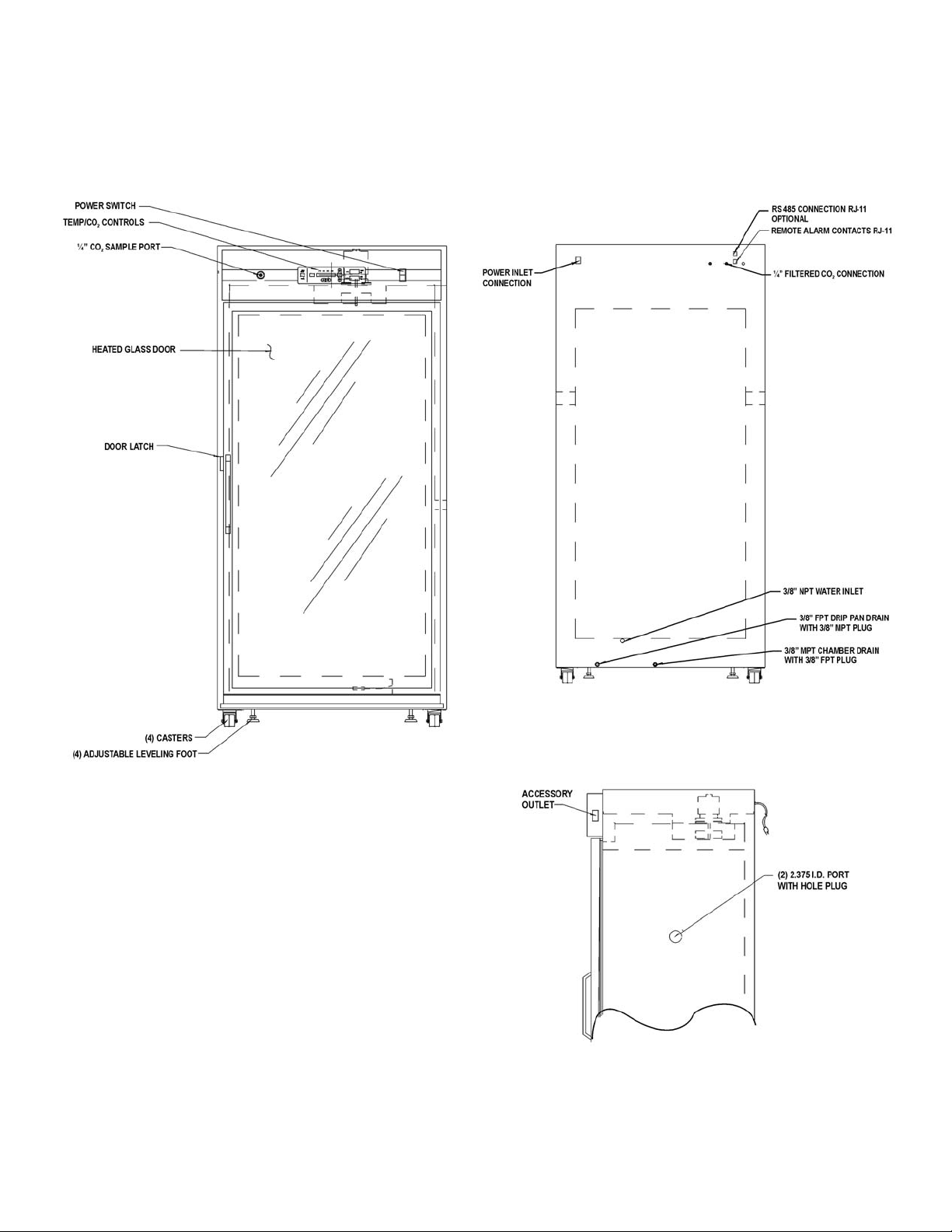
The incubator has serrated fittings on the back of the cabi-
net to connect the gas supply. Refer to Figure 1-2. The fitting is
labeled CO2Inlet #1 Tank. Make sure that the connections are
secured with clamps. Check all fittings for leaks.
For units having the CO2Gas Guard option, refer to
Section 6.2.
1.4 Incubator Start-Up
With the incubator properly installed, connected to power,
the humidity reservoir filled and the unit connected to a gas
supply, system setpoints can be entered. The following set-
points can be entered in Set Mode: Temperature,
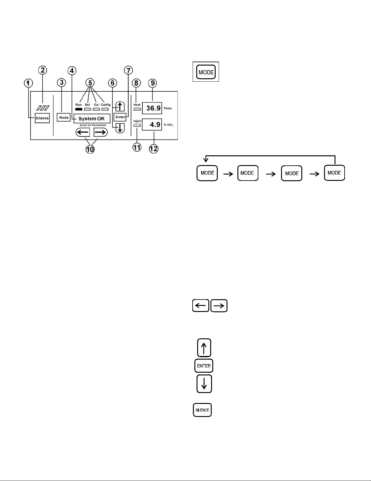
Overtemperature and CO2. To enter Set Mode, press the Mode
key until the Set indicator lights. Press the right and/or left
arrow keys until the proper parameter appears in the message
display center. See Chart 1-1 for more detail.
a. Setting the Operating Temperature
This incubator has an operating temperature range of
10.0°C to 60.0°C, depending on ambient temperature. It is
shipped from the factory with a temperature setpoint of 10.0°
C. At this setting, all heaters are turned off. To change the
operating temperature setpoint:
1. Press the Mode key until the Set indicator lights.
2. Press the right arrow until “Temp XX.X” is displayed in
the message center.
3. Press up/down until the desired temperature setpoint is
displayed.
4. Press Enter to save the setpoint.
5. Press the Mode key until the Run indicator lights for
Run mode or press the right/left arrow keys to go to
next/previous parameter.
Any equipment placed inside chamber must be
rated for unit operating temperature and humidity.
Model 3950/3951 ____________________________________________________________________Installation and Start-Up
1 - 5

b. Setting the Overtemp Setpoint
The independent overtemp system is designed as a
safety to protect the incubator only. It is not
intended to protect or limit the maximum tempera-
ture of the cell cultures or customer’s equipment
inside the incubator if an overtemp condition
occurs.
All Thermo Forma 3950 Series incubators are equipped
with a secondary temperature monitoring system to monitor the
air temperature inside the cabinet. This system is designed as a
safety device to turn off all heaters in the event of a temperature
control failure. The temperature control point in the incubator
will be approximately ±1°C of the overtemp setpoint.
The overtemp setpoint is set by the factory (default) at
40°C. However, the overtemp can be reset over a range from
0.5°C above the operating temperature setpoint to 65°C.
If the incubator’s operating temperature setpoint is set
above the overtemp setpoint, the overtemp setpoint will auto-
matically update to 1°C above the temperature setpoint. It is
recommended that the overtemp setpoint be maintained at 1°C
over the operating temperature setpoint.
To set the Overtemp setpoint:
1. Press the Mode key until the Set indicator lights.
2. Press the right arrow until Otemp XX.X is displayed in
the message center.
3. Press the up or down arrow until the desired Otemp set-
point is displayed.
4. Press Enter to save the setting.
5. Press the Mode key until the Run indicator lights, or
press the right or left arrow to go to the next or previous
parameter.
c. Setting the CO2Setpoint
All CO2cells are calibrated at the factory at 37°C,
medium humidity and 10% CO2. Therefore, if a temperature
setpoint of 37°C has been entered, the humidity reservoir has
been filled and the CO2control is set to run between 0-10%, the
CO2setpoint may be entered immediately. Otherwise, it is
important to allow the unit 12 hours to stabilize at the tempera-
ture setpoint before entering the CO2setpoint.
All models of the incubator have a CO2setpoint range of
0.0% to 20.0%. The incubator is shipped from the factory with
a CO2setpoint of 0.0%. At this setting, all CO2control and
alarms are turned off.
To change the CO2setpoint:
1. Press the Mode key until the Set indicator lights.
2. Press the right arrow until “CO2 XX.X” is displayed in
the message center.
3. Press the up/down arrow until the desired CO2setpoint
is displayed.
4. Press Enter to save the setpoint.
5. Press the Mode key until the Run indicator lights to go
to Run mode, or press the right/left arrow keys to go to
next/previous parameter.
Model 3950/3951 ____________________________________________________________________Installation and Start-Up
1 - 6

Model 3950/3951 ____________________________________________________________________Installation and Start-Up
1 - 7

Section 2 - Calibration
2.1 Calibration Mode
After the unit has stabilized, several different systems can
be calibrated. In the calibration mode, the air temperature, CO2
and RH levels can be calibrated to reference instruments. To
access the calibration mode, press the Mode key until the Cal
indicator lights. Press the right and/or left arrow until the prop-
er parameter appears in the message center. See Chart 2-1 at the
end of this section for more detail.
Calibration frequency is dependent on use, ambient condi-
tions and accuracy required. A good laboratory practice would
require at least an annual calibration check. On new installa-
tions, all parameters should be checked after the stabilization
period.
Prior to calibration, the user should be aware of the follow-
ing system functions. While the unit is in the calibration mode,
all system control functions are stopped so the unit remains sta-
ble. Readout of the system being calibrated will appear on the
message center. If no keys are pressed for approximately five
minutes while in Calibration mode, the system will reset to Run
mode so control functions are reactivated.
Before making any calibration or adjustments to
the unit, it is imperative that all reference instru-
ments be properly calibrated.
a. Calibrating the Temperature
Before calibration, allow the cabinet temperature to stabi-
lize. Place the calibrated instrument in the center of the cham-
ber. The instrument should be in the airflow, not against the
shelf.
Temperature Stabilization Periods
Start-Up - Allow 12 hours for the temperature in the cabinet to
stabilize before proceeding.
Presently Operating - Allow at least 2 hours after the display
reaches setpoint for temperature to stabilize before proceeding.
1. Press the Mode key until Cal indicator lights.
2. Press the right arrow until “TEMPCAL XX.X” appears
in the message center.
3. Press the up/down arrow to match the display to the cal-
ibrated instrument.
4. Press Enter to store calibration.
5. Press the Mode key to return to Run or the right/left
arrow to go to next/previous parameter.
b. Calibrating the CO2System
Model 3950 Series incubators have a CO2sensor. The incu-
bator atmosphere is not only effected by the quantity of CO2
present but also by the air temperature and water vapor present
in the incubator atmosphere. In monitoring the effects of CO2,
air temperature and absolute humidity must be held constant so
any change is caused by a change in CO2concentration.
Changing temperature or changing from elevated humidity
to room ambient humidity levels will require re-calibration of
the CO2control.
CO2Sensor Stabilization Periods
Start -Up - The CO2sensor has been calibrated at the factory
for 37°C and elevated humidity. Allow the temperature, humid-
ity and CO2levels in the chamber to stabilize at least 12 hours
before checking the CO2concentration with an independent
instrument.
Presently Operating - Make sure the chamber doors are
closed. Allow at least 2 hours after the temperature and CO2
displays reach their setpoints for chamber atmosphere stabiliza-
tion.
1. Make sure the stabilization periods outlined above are
followed.
2. Sample the chamber atmosphere through the sample port
with an independent instrument. Sample the atmosphere
at least 3 times to ensure accuracy of the instrument.
3. Press the Mode key until the Cal indicator lights.
4. Press the right arrow until “CO2 CAL XX.X” is dis-
played in the message center.
5. Press the up /down arrows to change the display to
match the independent instrument.
6. Press Enter to store the calibration.
7. Press the Mode key to return to Run or the right or left
arrows to go to the next/ previous parameter.
Model 3950/3951 _____________________________________________________________________________Calibration
2 - 1

Model 3950/3951 _____________________________________________________________________________Calibration
2 - 2

Section 3 - Configuration
3.1 Configuration Mode
Several features available in the Configuration Mode allow
custom setup of the incubator. These features are listed and
described below. All features may not be necessary in all appli-
cations, but are available if needed. To enter Configuration
mode, press the Mode key until the Config indicator lights.
Press the right and/or left arrow until the appropriate parameter
appears in the message center. See Chart 3-1 at the end of this
section for more detail.
a. Disabling the ADD WATER Alarm
All applications do not require humidity. For this reason,
the ADD WATER alarm can be disabled. The factory default
for the ADD WATER alarm is ON.
1. Press the Mode key until the Config indicator lights.
2. Press the right arrow until H2O ALM XXX is displayed
in the message center.
3. Press up/down arrow to toggle H2O ALM ON or OFF.
4. Press Enter to save the setting.
5. Press the Mode key to return to run mode or right/left to
go to next/previous parameter.
Note: Verify that the RH HIGH feature is set to OFF after dis-
abling the ADD WATER alarm.
b. Turning All Audible Alarms ON/OFF
The audible alarms can be turned on or off. The factory
setting is ON.
1. Press the Mode key until the Config indicator lights.
2. Press the right arrow until Audible XXX is displayed in
the message center.
3. Press up/down arrow to toggle Audible ON/OFF.
4. Press Enter to save the setting.
5. Press the Mode key to return to run mode or right/left to
go to next/previous parameter.
c. Setting an Access Code
A 3-digit Access Code can be entered to avoid unautho-
rized personnel from changing the setpoints, calibration, or con-
figuration. A setting of 000 will bypass the access code. The
factory setting is 000.
1. Press the Mode key until the Config indicator lights.
2. Press the right arrow until Acc Code XXX is displayed
in the message center.
3. Press up or down arrow to change the access code.
4. Press Enter to save the access code.
5. Press the Mode key to return to the Run mode or
right/left to go to next/previous parameter.
d. Setting Low Temp Alarm Limit (tracking alarm)
The low temp alarm limit is the deviation from the temper-
ature setpoint, which will cause a low temp alarm. The low
temp alarm is variable from 0.5° below setpoint to 5.0° below
setpoint. The factory setting is 1.0° below setpoint. A minus
sign in the display indicates that the alarm setting is below the
setpoint.
1. Press the Mode key until the Config indicator lights.
2. Press the right arrow until Temp Lo -X.X is displayed
in the message center.
3. Press up/down arrow to change the low temp alarm
limit.
4. Press Enter to save the low temp alarm limit.
5. Press the Mode key to return to Run mode or right/left
to go to next/previous parameter.
e. Enabling Temperature Alarms to Trip Relay
Contacts
The temperature alarms can be programmed to trip the
remote alarm contacts. A setting of ON will cause this, a set-
ting of OFF will not allow temperature alarms to trip the con-
tacts. The factory setting is ON.
1. Press the Mode key until the Config indicator lights.
2. Press the right arrow until TMP RLY XXX is displayed.
3. Press the up/down arrow to toggle the setting ON/OFF.
4. Press Enter to save the setting
5. Press the Mode key to return to Run or the right/left
arrow key to go to next/previous parameter.
Model 3950/3951 _____________________________________________________________________________Configuration
3 - 1

f. Setting Low CO2Alarm Limit (tracking alarm)
The low CO2alarm limit is the deviation from the CO2set-
point, which will cause a low CO2alarm. The setpoint is vari-
able from 0.5 % CO2below setpoint to 5.0 % CO2below set-
point. The factory setting is 1.0 % CO2below setpoint. A
minus in the display indicates that the alarm setting is below
the setpoint.
1. Press the Mode key until the Config indicator lights.
2. Press the right arrow until CO2 LO -X.X is displayed in
the message center.
3. Press up/down arrow to change the low CO2 alarm
limit.
4. Press Enter to save the low CO2 alarm limit.
5. Press the Mode key to return to Run mode or right/left
to go to next/previous parameter.
g. Setting High CO2Alarm Limit (tracking alarm)
The high CO2alarm limit is the deviation from the CO2set-
point, which will cause a high CO2alarm. The setpoint is vari-
able from 0.5 % CO2above setpoint to 5.0 % CO2above set-
point. The factory setting is 1.0 % CO2above setpoint.
1. Press the Mode key until the Config indicator lights.
2. Press the right arrow until CO2 HI X.X is displayed in
the message center.
3. Press up/down arrow to change the high CO2alarm
limit.
4. Press Enter to save the high CO2alarm limit.
5. Press the Mode key to return to run mode or right/left to
go to next/previous parameter.
h. Enabling CO2Alarms to Trip Relay Contacts
High and Low CO2alarms can be programmed to trip the
remote alarm contacts. A setting of ON will cause this, a set-
ting of OFF will not allow CO2alarms to trip the contacts. The
factory setting is ON.
1. Press the Mode key until the Config indicator lights.
2. Press the right arrow until CO2 RLY XXX is displayed
in the message center.
3. Press up/down arrow to toggle the setting ON/OFF.
4. Press Enter to save the setting.
5. Press the Mode key to return to Run Mode or right/left
to go to next/previous parameter.
i. Setting New Zero Number for New CO2Sensors
If a new CO2sensor is being installed, the two numbers on
the factory installed sticker on the cell must be entered to cali-
brate the CO2in the unit.
Note: For the technician’s convenience, a label containing the
two numbers on the cell is affixed inside the electronics drawer.
1. Press the Mode key until the Config indicator lights.
2. Press the right arrow until Z# XXXX is displayed in the
message center.
3. Press up/down arrow to change the zero number to
match the sticker.
4. Press Enter to save the setting.
5. Press the Mode key to return to Run mode or right/left
to go to next/previous parameter.
j. Setting New Span Number for CO2Sensors
If a new CO2sensor is being installed, the two numbers on
the factory installed sticker on the cell must be entered to cali-
brate the CO2in the unit.
Note: For the technician’s convenience, a label containing the
two numbers on the cell is affixed inside the electronics drawer.
1. Press the Mode key until the Config indicator lights.
2. Press the right arrow until S# XXXX is displayed in the
message center.
3. Press up/down arrow to change the span number to
match the sticker.
4. Press Enter to save the setting.
5. Press the Mode key to return to Run mode or right/left
to go to next/previous parameter.
k. Enabling the High Humidity Feature
In normal operation, the incubator will maintain the humid-
ity level above 80%. If a higher RH level is required, the RH
HIGH feature may be turned ON. This allows the heater
attached to the humidity reservoir to be enabled, resulting in
RH levels above 90%. The factory default for the RH HIGH
feature is OFF.
1. Press the Mode key until the Config indicator lights.
2. Press the right arrow until RH HIGH XXX is displayed
in the message center.
3. Press up/down arrow to toggle RH HIGH ON or OFF.
4. Press Enter to save the setting.
5. Press the Mode key to return to Run mode or right/left
to go to next/previous parameter.
Note: Verify that the ADD WATER alarm is set to ON after
enabling the RH HIGH feature.
Model 3950/3951 _____________________________________________________________________________Configuration
3 - 2

l. Selecting a Primary Tank w/ Gas Guard Option
On units equipped with the Gas Guard option, a primary
tank can be selected. The primary tank will be either Tank 1 or
2. The factory setting is Tank 1 .
1. Press the Mode key until the Config indicator lights.
2. Press the right arrow until Tank Sel X is displayed in the
message center.
3. Press the up/down arrow to toggle the setting between 1
and 2 .
4. Press Enter to save the setting.
5. Press the Mode key to return to Run mode or right/left
to go to next/previous parameter.
m. Enabling the Gas Guard System
On units equipped with the Gas Guard option, the Gas
Guard system may be turned ON or OFF if it is not in use. The
factory setting is OFF.
1. Press the Mode key until the Config indicator lights.
2. Press the right arrow until Gas Grd XX is displayed in
the message center.
3. Press up/down arrow to toggle the setting ON/OFF.
4. Press Enter to save the setting.
5. Press the Mode key to return to Run mode or right/left
to go to next/previous parameter.
n. Setting RS485 Communications Address
(1535 compatible only)
On units that have the RS485 option, direct communication
with the Thermo Forma 1535 Model alarm system can be
established. Each piece of equipment connected to the 1535
must have a unique address. An address of 0-24 can be entered
for the incubator. A setting of 0 is an invalid address that the
1535 will ignore. The factory setting for the RS485 address is
0.
1. Press the Mode key until the Config indicator lights.
2. Press the right arrow until RS485 XX is displayed in the
message center.
3. Press up/down arrow to move the RS485 address.
4. Press Enter to save the RS485 address.
5. Press the Mode key to return to Run mode or right/left
to go to next/previous parameter.
Model 3950/3951 _____________________________________________________________________________Configuration
3 - 3

Model 3950/3951 _____________________________________________________________________________Configuration
3 - 4

Model 3950/3951 _____________________________________________________________________________Configuration
3 - 5

Section 4 - Alarms
4.1 Alarms
The Model 3950 Series incubator is equipped with a sys-
tem which notifies the user of an alarm condition inside the
incubator. All alarms are displayed in the control panel message
center. The following table contains information on all possible
systems alarms.
To avoid alarms going off in day-to-day use, some alarms
are equipped with a time delay feature. For this to function cor-
rectly, the alarm condition must exist for the specified length of
time before the message center will display the alarm. This
allows for interruptions, such as door openings, to occur with-
out the incubator going into a continuous state of alarm.
When an alarm condition exists, the Silence key can be
pressed to temporarily mute the audible alarm. The message
center will continue to show the alarm condition. If the alarm
condition is not corrected within a specified length of time, the
alarm will sound again or “ringback” to remind the user.
When multiple alarm conditions occur, active messages are
displayed in the display center one at a time, updating at 5-sec-
ond intervals. Pressing Silence during multiple alarms causes
all active alarms to be muted and to ringback in 15 minutes.
The temperature alarms are disabled when the Temp set
point is 10°C. The CO2alarms are disabled when the CO2set
point is 0.0%.
Model 3950/3951 _________________________________________________________________________________Alarms
4 - 1
4.2 Sensor Fault Alarms
The microprocessor in 3950 Series incubators continually
scans all available sensors to ensure that they are operating
properly. Should an error be detected, the incubator will sound
an alarm and display the appropriate message. If such an alarm
occurs, contact your local distributor or the Thermo Forma
Service department at 740-373-4763 or 1-888-213-1790
(U.S.A. and Canada) or fax 740-373-4189.
Description Message Code Delay Ringback Relay
No alarm condition exists SYSTEM OK ----- ----- -----
Temp > Otemp Set point SYS IN OTEMP 0 min. 15 min. Yes
Air Temp Sensor Fault (See Section 4.2) TMP SENS ERR 0 min. 15 min. No
Temperature Controller Failure (See Section 4.2) TMP CTRL ERR 0 min. 15 min. YES
CO2Sensor Fault (See Section 4.2) CO2 SENS ERR 0 min. 15 min. No
Water Level in Reservoir is Low ADD WATER 0 min. 15 min. No
Inner Door is Open DOOR OPEN 15 min. 15 min. No
CO2> CO2 High Tracking Alarm CO2 IS HIGH 15 min. 15 min. Programmable
CO2< CO2 Low Tracking Alarm CO2 IS LOW 15 min. 15 min. Programmable
TEMP < TEMP Low Tracking Alarm TEMP IS LOW 15 min. 15 min. Programmable
Tank 1 is low, switch to Tank 2 (Gas Guard only) TANK1 LOW 0 min. ---- No
Tank 2 is low, switch to Tank 1 (Gas Guard only) TANK2 LOW 0 min. ---- No
Both tanks are low (Gas Guard only) TANK 1 and 2 LOW 0 min. 15 min. No
- All alarm delays and ringback times are + 30 seconds -
This manual suits for next models
1
Table of contents
Other Thermo Forma Accessories manuals
Popular Accessories manuals by other brands

Acuity Brands
Acuity Brands Synergy LIRO H installation instructions

Campbell
Campbell CS115 instruction manual

STEINEL
STEINEL IS D360-120 installation instructions

Kogan
Kogan Cordless Portable Travel Water Flosser user guide

Whale
Whale Easi-Slide Installation and operating instructions

Ambient Weather
Ambient Weather WH31SM manual