Thermo Forma 3110 Series Operating instructions

-~
ARTISAN
®
~I
TECHNOLOGY
GROUP
Your definitive source
for
quality
pre-owned
equipment.
Artisan Technology
Group
Full-service,
independent
repair
center
with
experienced
engineers
and
technicians
on staff.
We
buy
your
excess,
underutilized,
and
idle
equipment
along
with
credit
for
buybacks
and
trade-ins
.
Custom
engineering
so
your
equipment
works
exactly as
you
specify.
•
Critical
and
expedited
services
•
Leasing
/
Rentals/
Demos
• In
stock/
Ready-to-ship
•
!TAR-certified
secure
asset
solutions
Expert
team
ITrust
guarantee
I
100%
satisfaction
All
tr
ademarks,
br
a
nd
names, a
nd
br
a
nd
s a
pp
earing here
in
are
th
e property of
th
e
ir
r
es
pecti
ve
ow
ner
s.
Visit our website - Click HERE

Model: 3110 Series*
CO2Water Jacketed Incubator
Series II
Operating and Maintenance Manual
Manual No: 7033110 Rev. 9
*Refer to listing of all models on Page i.
Artisan Technology Group - Quality Instrumentation ... Guaranteed | (888) 88-SOURCE | www.artisantg.com

Model 3110/3210 Series ___________________________________________________________________________
i
Read This Instruction Manual.
Failure to read, understand and follow the instructions in
this manual may result in damage to the unit, injury to operat-
ing personnel, and poor equipment performance.
CAUTION! All internal adjustments and maintenance must
be performed by qualified service personnel.
Refer to the serial tag on the back of this manual.
The material in this manual is for information purposes
only. The contents and the product it describes are subject to
change without notice. Thermo Forma makes no representations
or warranties with respect to this manual. In no event shall
Thermo Forma be held liable for any damages, direct or inciden-
tal, arising out of or related to the use of this manual.
Single Chamber Models
Model CO2 Sensor* O2Voltage**
3110 T/C No 115
3111 T/C No 230
3120 IR No 115
3121 IR No 230
3130 T/C Yes 115
3131 T/C Yes 230
3140 IR Yes 115
3141 IR Yes 230
*T/C is a thermal conductivity sensor. IR is an infrared
sensor.
**All units are 50/60 Hz.
MANUAL NUMBER 7033110
9 20221/IN-2959 3/4/02 Updated 200 drawing for use with Models 5050/5060 Series (display bd) ccs
-- 20581/IN-3015 1/21/02 Corrected temp sensor error sequence in chart on 4-1 ccs
-- 20484 11/21/01 Removed all specific references to Model 2095 bath ccs
8 20374/IN-2994 11/7/01 Updated 200 drawing - Kaizen, board hardware ccs
7 20336/PIP-034 10/10/01 Removed blower motor cover, added nylon cable clamps ccs
-- 20015/IN-2942 5/21/01 Removed top shelf tab from side duct for better HEPA fit ccs
6 19866/IN-2907 3/19/01 Updated O2fuel cell warranty info from 2 years to 1 ccs
5 19473 2/20/01 Added water jacket rust inhibitor information ccs
REV ECR/ECN DATE DESCRIPTION By
Contains Parts and Assemblies
Susceptible to Damage by
Electrostatic Discharge (ESD)
CAUTION
Artisan Technology Group - Quality Instrumentation ... Guaranteed | (888) 88-SOURCE | www.artisantg.com

Model 3110/3210 Series ___________________________________________________________________________
ii
Important operating and/or maintenance instructions. Read the accompanying text carefully.
Ce symbole attire l'attention de l'utilisateur sur des instructions importantes de fonctionnement et/ou d'entretien. Il
peut être utilisé seul ou avec d'autres symboles de sécurité. Lire attentivement le texte d'accompagnement.
Wichtige Betriebs- und/oder Wartungshinweise. Lesen Sie den nachfolgenden Text sorgfältig.
Importante instruccions de operacion y/o mantenimiento. Lea el texto acompanante cuidadosamente.
Potential electrical hazards. Only qualified persons should perform procedures associated with this symbol.
Ce symbole attire l'attention de l'utilisateur sur des risques électriques potentiels. Seules des personnes qualifiées
doivent appliquer les instructions et les procédures associées à ce symbole.
Gefahr von Stromschlägen. Nur qualifizierte Personen sollten die Tätigkeiten ausführen, die mit diesem Symbol beze-
ichnet sind.
Potencial de riesgos electricos. Solo personas das capacitadadas deben ejecutar los procedimientos asociadas con este
simbulo.
Equipment being maintained or serviced must be turned off and locked off to prevent possible injury.
Risques potentiels liés à l'énergie. L'équipement en entretien ou en maintenance doit être éteint et mis sous clé pour
éviter des blessures possibles.
Geräte, an denen Wartungs- oder Servicearbeiten durchgeführt werden, müssen abgeschaltet und abgeschlossen wer-
den, um Verletzungen zu vermeiden.
El equipo recibiendo servicio o mantenimiento debe ser apagado y segurado para prevenir danos.
Hot surface(s) present which may cause burns to unprotected skin, or to materials which may be damaged by elevated
temperatures.
Présence de surface(s) chaude(s) pouvant causer des brûlures sur la peau non protégée, ou sur des matières pouvant
être endommagées par des températures élevées.
Heiße Oberfläche(n) können ungeschützter Haut Verbrennungen zufügen oder Schäden an Materialien verursachen,
die nicht hitzebeständig sind.
Superficias calientes que pueden causar quemaduras a piel sin proteccion o a materiales que pueden estar danados
por elevadas temperaturas.
√ Always use the proper protective equipment (clothing, gloves, goggles, etc.)
√ Always dissipate extreme cold or heat and wear protective clothing.
√ Always follow good hygiene practices.
√ Each individual is responsible for his or her own safety.
Artisan Technology Group - Quality Instrumentation ... Guaranteed | (888) 88-SOURCE | www.artisantg.com

Model 3110/3210 Series ___________________________________________________________________________
iii
Artisan Technology Group - Quality Instrumentation ... Guaranteed | (888) 88-SOURCE | www.artisantg.com

q. Enabling O2Alarms to Trip Contacts . . . . . . . . . .3 - 3
r. Enabling Temp/RH to be Displayed . . . . . . . . . . .3 - 4
s. Enabling CO2/O2to be Displayed . . . . . . . . . . . . .3 - 4
t. Selecting a Primary Tank w/ Gas Guard Option . .3 - 4
u. Enabling the Gas Guard System . . . . . . . . . . . . . .3 - 4
v. Setting a RS485 Communications Address . . . . .3 - 4
Section 4 - Alarms . . . . . . . . . . . . . . . . . . . . . . . . . . . . . .4 - 1
4.1 Alarms . . . . . . . . . . . . . . . . . . . . . . . . . . . . . . . . . . . .4 - 1
4.2 Sensor Fault Alarms . . . . . . . . . . . . . . . . . . . . . . . . . .4 - 2
a. REPL O2 SNSR (Alarm) . . . . . . . . . . . . . . . . . . .4 - 2
b. O2 SNSR ERR (Alarm) . . . . . . . . . . . . . . . . . . . .4 - 2
c. CO2 SNSR ERR . . . . . . . . . . . . . . . . . . . . . . . . . .4 - 2
d. IR AUTOZ ERR . . . . . . . . . . . . . . . . . . . . . . . . . .4 - 2
Section 5 - Routine Maintenance . . . . . . . . . . . . . . . . . . .5 - 1
5.1 Disinfecting the Incubator Interior . . . . . . . . . . . . . .5 - 1
5.2 Cleaning the Cabinet Exterior . . . . . . . . . . . . . . . . . .5 - 2
5.3 Cleaning the Humidity Pan . . . . . . . . . . . . . . . . . . . . .5 - 2
5.4 Reversing the Door Swing . . . . . . . . . . . . . . . . . . . . .5 - 2
a. Reversing the Hinges for Exterior Door . . . . . . . .5 - 2
5.5 Replacing Fuses . . . . . . . . . . . . . . . . . . . . . . . . . . . .5 - 3
5.6 HEPA Filter Maintenance . . . . . . . . . . . . . . . . . . . . .5 - 6
5.7 Replacing the Air Sample Filter . . . . . . . . . . . . . . . .5 - 7
5.8 Replacing the Access Port Filter . . . . . . . . . . . . . . . .5 - 7
5.9 Draining Water Jacket . . . . . . . . . . . . . . . . . . . . . . . .5 - 7
5.10 O2Sensor Fuel Cell . . . . . . . . . . . . . . . . . . . . . . . . . .5 - 7
5.11 Replacing the O2Sensor . . . . . . . . . . . . . . . . . . . . . .5 - 7
5.12 Adding or Replenishing the W/J Rust Inhibitor . . . .5 - 8
Section 6 - Factory Installed Options . . . . . . . . . . . . . . . .6 - 1
6.1 Connections to External Equipment . . . . . . . . . . . . .6 - 1
a. Connecting the Remote Alarm Contacts . . . . . . .6 - 1
b. Connecting the RS485 Interface . . . . . . . . . . . . . .6 - 1
c. Connecting the Analog Output Boards . . . . . . . . .6 - 1
6.2 Gas Guard for CO2or N2. . . . . . . . . . . . . . . . . . . . . .6 - 2
a. Connecting the CO2Gas Supplies . . . . . . . . . . . . .6 - 2
b. Connecting the N2Gas Supplies . . . . . . . . . . . . . .6 - 2
c. Activating the Built-in Gas Guard: . . . . . . . . . . . .6 - 3
d. Operation of the CO2or N2Gas Guard: . . . . . . . .6 - 3
6.3 Humidity Readout . . . . . . . . . . . . . . . . . . . . . . . . . . . .6 - 3
a. Factors Affecting Humidity Level in Chamber: . .6 - 3
b. Accuracy of the Humidity Readout: . . . . . . . . . . .6 - 4
6.4 Factory Installed Cooling Coil . . . . . . . . . . . . . . . . .6 - 4
a. Installing the Cooling Coil Incubator . . . . . . . . . .6 - 4
Section 7 - Specifications . . . . . . . . . . . . . . . . . . . . . . . . .7 - 1
Section 8 - Spare Parts . . . . . . . . . . . . . . . . . . . . . . . . . . .8 - 1
Section 9 - Electrical Schematics . . . . . . . . . . . . . . . . . . .9 - 1
Section 10 - Warranty Information . . . . . . . . . . . . . . . . . . . . . .
Appendix A - Supplements . . . . . . . . . . . . . . . . . . . . . . . . . . . .
Model 3110/3210 Series ____________________________________________________________Table of Contents
Table of Contents
Section 1 - Installation and Start-up . . . . . . . . . . . . . . . . .1 - 1
1.1 Name and Description of Parts . . . . . . . . . . . . . . . . .1 - 1
1.2 Control Panel Keys, Displays and Indicators . . . . . . .1 - 2
1.3 Operating the Control Panel . . . . . . . . . . . . . . . . . . .1 - 2
1.4 Displays . . . . . . . . . . . . . . . . . . . . . . . . . . . . . . . . . .1 - 3
1.5 Installing the Unit . . . . . . . . . . . . . . . . . . . . . . . . . . .1 - 4
a. Choosing the Location . . . . . . . . . . . . . . . . . . . . .1 - 4
b. Stacking the Incubators . . . . . . . . . . . . . . . . . . . .1 - 4
c. Preliminary Cleaning and Disinfecting . . . . . . . .1 - 5
d. Installing the Access Port Filter . . . . . . . . . . . . . .1 - 5
e. Installing the Air Sample Filter . . . . . . . . . . . . . . .1 - 5
f. Installing the HEPA Filter . . . . . . . . . . . . . . . . . . .1 - 5
g. Installing the Shelves . . . . . . . . . . . . . . . . . . . . . . .1 - 6
h. Leveling the Unit . . . . . . . . . . . . . . . . . . . . . . . . .1 - 6
i. Connecting the Unit to Electrical Power . . . . . . . .1 - 6
j. Filling the Water Jacket . . . . . . . . . . . . . . . . . . . .1 - 6
k. Filling the Humidity Pan . . . . . . . . . . . . . . . . . . .1 - 6
l. Connecting the CO2Gas Supply . . . . . . . . . . . . . .1 - 7
m. Connecting the N2Gas Supply . . . . . . . . . . . . . . .1 - 8
1.6 Incubator Start-Up . . . . . . . . . . . . . . . . . . . . . . . . . . .1 - 8
a. Setting the Operating Temperature . . . . . . . . . . . .1 - 8
b. Setting the Overtemp Setpoint . . . . . . . . . . . . . . .1 - 9
c. Setting the CO2Setpoint . . . . . . . . . . . . . . . . . . . .1 - 9
d. Setting the O2Setpoint . . . . . . . . . . . . . . . . . . . . .1 - 9
Section 2 - Calibration . . . . . . . . . . . . . . . . . . . . . . . . . . .2 - 1
2.1 Calibration Mode . . . . . . . . . . . . . . . . . . . . . . . . . . . .2 - 1
a. Calibrating the Temperature . . . . . . . . . . . . . . . . .2 - 1
b. Calibrating Thermal Conductivity CO2System . .2 - 1
c. Calibrating the Infra-Red CO2System. . . . . . . . .2 - 1
d. Calibrating the O2System . . . . . . . . . . . . . . . . . .2 - 2
e. Calibrating Relative Humidity . . . . . . . . . . . . . . .2 - 3
Section 3 - Configuration . . . . . . . . . . . . . . . . . . . . . . . . .3 - 1
3.1 Configuration Mode . . . . . . . . . . . . . . . . . . . . . . . . . .3 - 1
a. Turning the Audible Alarm ON/OFF . . . . . . . . . .3 - 1
b. New HEPA Filter . . . . . . . . . . . . . . . . . . . . . . . . .3 - 1
c. Setting the REPLACE HEPA filter reminder . . . .3 - 1
d. Setting an Access Code . . . . . . . . . . . . . . . . . . . .3 - 1
e. Setting Low Temp Alarm Limit (tracking alarm) 3 - 1
f. Setting High Temp Alarm Limit (tracking alarm) 3 - 2
g. Enabling Temperature Alarms to Trip Contacts . .3 - 2
h. Setting Low CO2Alarm Limit (tracking alarm) .3 - 2
i. Setting High CO2Alarm Limit (tracking alarm) . .3 - 2
j. Enabling CO2Alarms to Trip Contacts . . . . . . . . .3 - 2
k. Setting New Zero Number for T/C CO2Sensors .3 - 2
l. Setting New Span Number for T/C CO2Sensors .3 - 3
m. Setting a Low RH Alarm Limit . . . . . . . . . . . . . .3 - 3
n. Enabling RH Alarms to Trip Contacts . . . . . . . . .3 - 3
o. Setting a Low O2Alarm Limit (tracking alarm) .3 - 3
p. Setting a High O2Alarm Limit (tracking alarm) .3 - 3
iv
Artisan Technology Group - Quality Instrumentation ... Guaranteed | (888) 88-SOURCE | www.artisantg.com

Model 3110/3210 Series ________________________________________________________Installation and Start-Up
1 - 1
Section 1 - Installation and Start-up
1.1 Name and Description of Parts
Heated Glass
Inner Door
Leveling
Legs (4)
Jacket Vent
Fill Port
Jacket
Drain
(remove plug
before using)*
Control Panel
Chamber Gas
Sample Port
Power
Switch
Hose
Barb
Insert
Figure 1-1
Water Jacket Incubator
• Outer Door - Reversible to opposite swing, see Section
5.4
• Heated Inner Door - Keeps chamber interior dry.
Reversible to opposite swing, see Section 5.4.
• Chamber Gas Sample Port - Used for sampling chamber
CO2content, using a Fyrite or similar instrument.
Should be capped when controlling O2.
• Main Power Switch
• Control Panel - Keypad, Displays and Indicators. (See
Figure 1-2).
• Fill Port - Used for filling the water jacket.
• Water Jacket Vent- Do not cover! Allows air to escape
from the water jacket during filling and normal expan-
sion and contraction when the incubator heats or cools.
• Leveling Legs - Used to level the unit.
• Water Jacket Drain – Remove plug and use hose barb
insert included. Plug when not in use.
Note: The incubators are stackable. See Section 1.5.
*When setting up the incubator, install the cover plate
packed inside the incubator shipping carton.
Artisan Technology Group - Quality Instrumentation ... Guaranteed | (888) 88-SOURCE | www.artisantg.com

Model 3110/3210 Series ________________________________________________________Installation and Start-Up
1 - 2
KInject Indicator: Lights when gas is being injected into the
incubator. If the %CO2/O2display (item L) is continuously
displaying CO2, the light indicates CO2injection only. If
the %CO2/O2display is continuously displaying O2, light
indicates N2injection. If the %CO2/O2is toggling, either a
CO2or N2injection will cause the indicator to light.
L%CO2/O2display: Can be programmed to display CO2con-
tinuously or O2continuously (on units equipped with O2),
or toggle between CO2and O2(on units equipped with O2)
See Section 3.1, Configuration.
1.3 Operating the Control Panel
The Model 3110 Series water jacket incuba-
tor has four basic modes, which allow incubator
setup. The modes are as follows: Run, Setpoints,
Calibration and System Configuration.
•Run is the default mode that the incubator will normally be
in during operation.
•Set is used to enter system setpoints for incubator opera-
tion.
•Cal is used to calibrate various system parameters to the
customer’s satisfaction.
•Config is the system configuration mode that allows for
custom setup of various options.
1.2 Control Panel Keys, Displays and Indicators
Figure 1-2 Control Panel
CLASS 100
Silence Mode
36.9
4.9
Enter
Run Set Cal Config Heat Temp
Inject % CO2
Scroll for Parameters
ASILENCE - Silences the audible alarm.
BAlarm Indicator - Pulses on/off during an alarm condition
in the cabinet.
CMODE Select Switch - Used to select Run, Setpoints,
Calibration and System Configuration Modes.
DMessage Center - Displays system status.
EMode Select Indicators-
Run: Run Menu
Set: Set Points Menu
Cal: Calibrate Menu
Config: Configuration Menu
FUp and Down Arrows: Increases or decreases the parame-
ter values that are numbers, toggles the parameter values
that are choices.
GEnter: Accepts changes to the calibration settings
HHeat Indicator: Lights when power is applied to the
heaters.
ITemp Display: Can be programmed to display temperature
continuously, RH continuously (with RH option), or toggle
between temperature and humidity (with RH option). See
Section 3.1, Configuration.
JScroll for Parameters Keys: Scrolls the operator through
the parameters of the mode that is selected.
Artisan Technology Group - Quality Instrumentation ... Guaranteed | (888) 88-SOURCE | www.artisantg.com

Silence Key: Press to silence the audible alarm.
See Section 4 for alarm ringback times.
1.4 Displays
Message Center
Displays the system status (Mode) at all times. Displays
CLASS 100 or SYSTEM OK during normal operation, or alarm
messages if the system detects an alarm condition. See Section
4.1, Alarms. The display message CLASS 100 is a timing mech-
anism indicating that, under normal operating conditions with the
HEPA filter installed, the air inside the chamber meets the Class
100 air cleanliness standard for particulates of 0.5 micron size or
larger per cubic foot of air. (For further information on the Class
100 classification of air quality, see Appendix A.)
Upper and Lower Displays
These 7-segment displays vary depending upon the options
present and the configuration chosen. The upper display can
display temp or RH, or toggle between them. The bottom dis-
play can display CO2or O2, or toggle between them. See
Section 3.1, Configuration.
Model 3110/3210 Series ________________________________________________________Installation and Start-Up
Scroll for Parameters Keys: Steps the
operator through the parameters of SET,
CAL and CONFIG Modes. The right
arrow goes to the next parameter, the
left arrow returns to the previous param-
eter.
Up Arrow: Increases or toggles the parameter
value that has been selected in the SET, CAL, and
CONFIG Modes.
Enter: Must press Enter key to save to memory
all changed values.
Down Arrow: Decreases or toggles the parameter
values that have been selected in the SET, CAL
and CONFIG Modes.
RUN SETPOINT CALIBRATION CONFIGURATION
Default Mode Temperature Temp Offset Audible
Overtemp CO2 Cal New HEPA timer
CO2 IR CO2 Span Replace HEPA reminder
O2 O2 Cal at 20.7% Access Code
O2 Offset Temp Lo Alarm
RH Offset Temp Hi Alarm
Temp Relay
CO2 Lo Alarm
CO2 Hi Alarm
CO2 Relay
CO2 Z & S #’s
RH Lo Alarm
RH Relay
O2 Lo Alarm
O2 Hi Alarm
O2 Relay
Display 1 Setup
Display 2 Setup
Gas Guard Setup
RS485 Address
**Base Unit Displays
**Option Displays
The chart below shows the selections under each of the modes.
1 - 3
Artisan Technology Group - Quality Instrumentation ... Guaranteed | (888) 88-SOURCE | www.artisantg.com
Model 3110/3210 Series ________________________________________________________Installation and Start-Up
1 - 4
1.5 Installing the Unit
a. Choosing the Location
1. Locate the unit on a firm, level surface capable of sup-
porting the unit’s operational weight of 365 lbs. (166kg).
2. Locate away from doors and windows and heating and
air conditioning ducts.
3. Allow enough clearance behind the unit for electrical
and gas hook-up.
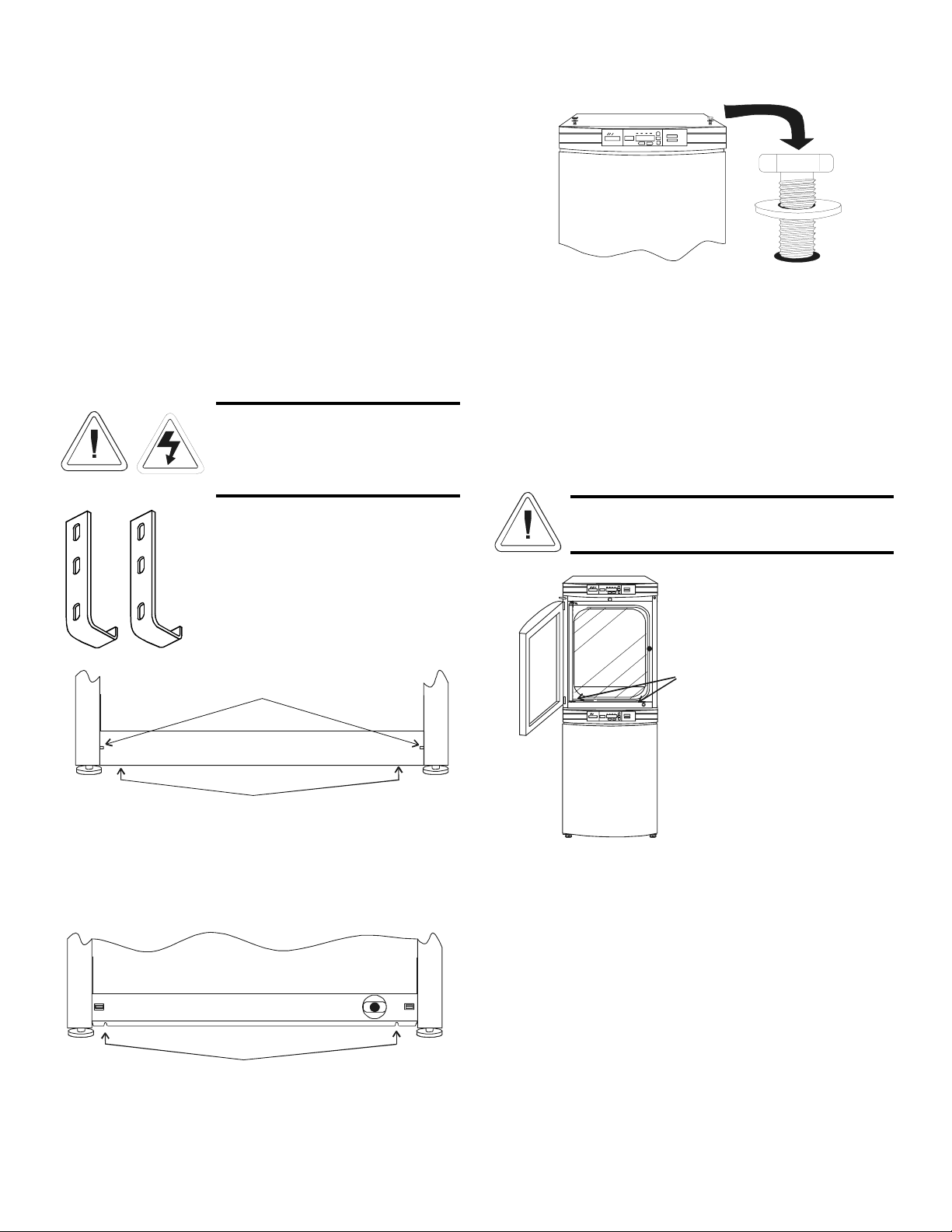
b. Stacking the Incubators
If the units have been in service,
disconnect the power cord connector
and drain the water jacket of the
designated top unit before stacking.
Note: Stacking brackets (shown at left)
stacking bolts, washers, and bolts for
stacking are included with each unit.
Figure 1-3 Stacking brackets
1. Designate one incubator to be the top unit and the other
as the bottom unit. Remove the base cover plate from
the top unit using the finger holes in the base or using a
slotted screwdriver. (Figure 1-4)
2. Note the two slots in the base of the incubator which
accommodate the stacking bolts. Refer to Figure 1-5.
3. Remove the two plastic plugs from the bolt holes in the
exterior top of the bottom unit. Install the 1/2” long
5/16-18 stacking bolts and washers into the bolt holes -
do not tighten the bolts at this time. Refer to Figure 1-6.
4. Unscrew and remove the leveling feet from the top unit
and lift it onto the bottom unit, off-setting the base of
the top unit approximately 2-3 inches behind the stack-
ing bolts and washers.
This incubator weighs 265 lbs (120kg) before
filling. Have sufficient personnel to lift it.
5. Align the sides of the top unit with the bottom unit and
slide the top unit forward until the slots in the base of
the top unit align with the 5/16” - 18 stacking bolts in
the exterior top of the bottom unit. Refer to Figure 1-7.
Front of top Incubator
Screwdriver slots
Finger holes
Base cover plate
Figure 1-4
Front of top Incubator, base cover plate removed
Slots for stacking bolts
Figure 1-5
5/16"-18 stacking bolt
and washer
Figure 1-6
(2) 5/16" bolts and flat washer
½” (13mm) wrench required
Figure 1-7
Artisan Technology Group - Quality Instrumentation ... Guaranteed | (888) 88-SOURCE | www.artisantg.com

6. Remove and save the two screws from the back of the
control panel on the bottom unit as identified in Figure
1.8.
7. Insert the stacking brackets into the slots on the rear of
the control panel of the bottom unit as shown in Figure
1-5. Align the slots in the brackets with the mounting
holes on the rear of the incubators. Secure the brackets
with the screws saved above and the 1/4-20 bolts pro-
vided in the stacking kit. A 7/16” wrench or socket will
be required for the bolts.
8. Secure the base of the top unit to the exterior top of the
bottom unit by tightening the 5/16-18 stacking bolts
using a 1/2” (13mm) wrench or suitable tool.
9. Replace the base cover on the top unit.
10. The stacked units are ready to be placed into service.
c. Preliminary Cleaning and Disinfecting
1. Remove the protective plastic coating on the shelf sup-
ports and air duct, if present.
2. Using a suitable laboratory disinfectant, disinfect all
interior surfaces including shelves and shelf supports,
door gaskets, blower wheel and CO2sensor. Refer to
Section 5.1.
d. Installing the Access Port Filter
Locate the opening in the top left corner of the interior
chamber. Remove the tape from the opening on the outside of
the unit. Locate the stopper with filter in the hardware bag.
Install in the opening inside the chamber. See Figure 1-12.
e. Installing the Air Sample Filter
1. Remove the filter from the shipping bag.
2. Separate one section of the tubing from the filter. Install
this section to the fitting on the blower plate.
3. After installing the top duct, connect the filter assembly
to the tubing coming through the top duct.
4. Insert the free end of the air sample filter tubing into the
larger hole in the back of the blower scroll. See Figure
1-9 for completed configuration.
f. Installing the HEPA Filter
1. Remove the filter from the shipping box.
2. Remove the plastic coating from the filter, using caution
not to touch the filter media.
3. Install the filter as shown in Figure 1-9.
4. To set-up an automatic REPLACE HEPA reminder, see
Sections 3b and 3c.
Use caution when handling the filter. The media
can be damaged if it is mishandled.
To avoid damage to the incubator, do not operate
the unit without the HEPA filter in place.
Model 3110/3210 Series ________________________________________________________Installation and Start-Up
1 - 5
Back of top Incubator
Back of bottom Incubator
Figure 1-8
Insert 1/4-20 bolts
Remove this screw
and install bracket
Stacking brackets
Figure 1-9
Artisan Technology Group - Quality Instrumentation ... Guaranteed | (888) 88-SOURCE | www.artisantg.com

Model 3110/3210 Series ________________________________________________________Installation and Start-Up
1 - 6
g. Installing the Shelves
1. Install the side ducts with the tabs facing into the center
of the chamber with their slots up. There are no right
side or left side ducts, simply rotate one of them to fit
the opposite side. Tilt the side ducts as they are placed in
the chamber so the tops fit into the top air duct, then
guide them into the vertical position. Figure 1-10 shows
the duct as it would be oriented for the right side of the
chamber.
2. Referring to Figure 1-10, note that there is no difference
between left and right side shelf channels.
3. Install the shelf channels by placing the channel’s rear
slot over the appropriate rear tab on the side duct. Pull
the shelf channel forward and engage the channel’s front
slot into the side duct’s appro-
priate forward tab. Refer to
Figure 1-11.
4. Figure 1-12 shows one of the
channels installed on the right
side duct.
h. Leveling the Unit
Check the unit for being level by placing a bubble-style
level on one of the shelves. Turn the hex nut on the leveler
counterclockwise to lengthen the leg, or clockwise to shorten it.
Level the unit front-to-back and left-to-right.
i. Connecting the Unit to Electrical Power
See the serial tag on the side of the unit for electrical speci-
fications, or refer to the electrical schematics in Section 9 of
this manual.
Connect the incubator to a grounded dedicated
circuit only.
The power cord connector is the mains discon-
nect device for the incubator. Position the unit so
that it can be easily disconnected.
Plug the provided power cord into the power inlet connec-
tor (See Figure 1-13) and into the grounded dedicated circuit.
Electrical Specifications: Models 3110, 3120, 3130, 3140 -
115V, 50/60Hz, 3.6A, 1 PH, 2W
Models 3111, 3121, 3131, 3141 -
230V, 50/60Hz, 2.0A, 1 PH, 2W
.
j. Filling the Water Jacket
Turn the power switch on. ADD WATER will appear in the
message center. Press the Silence key to silence the alarm.
Note: The fill port has a plug that must be removed before fill-
ing and replaced after filling is complete.
Chlorine is detrimental to stainless steel. Using
chlorinated tap water will void the water-jacket
warranty!
Note: High purity water (1M to 18M ohm/cm resistivity) is a
very aggressive solvent and is considered slightly acidic. Ideal
pH for the water in the jacket is 7. Sodium hydroxide may be
used to change the pH of high purity water. It requires approxi-
mately 8ml of 0.05 normal sodium hydroxide per gallon of high
purity water to raise the pH to 7. The water jacket holds appox-
imately 12 gallons. Sodium hydroxide and the rust inhibitor
may be used in the same water jacket.
Side duct
tab
Shelf channel
rear slot
Shelf channel
front slot
Side duct
tab
Side Ducts
Shelf Channels
Side toward shelf
Figure 1-10
Figure 1-12
Figure 1-11
Artisan Technology Group - Quality Instrumentation ... Guaranteed | (888) 88-SOURCE | www.artisantg.com

Model 3110/3210 Series ________________________________________________________Installation and Start-Up
1 - 7
Fill the water jacket with 11.7 gallons (43.5 liters) of dis-
tilled water with a resistance range of 50K to 1M Ohm/cm
(conductivity range of 20.0 to 1.0 uS/cm). Vinyl tubing and a
funnel for filling are included in the accessory bag shipped with
the unit. Connect vinyl tubing to the fill port. See Figure 1.1.
When the jacket is full, the audible alarm will sound a con-
tinuous tone for 10 seconds and the alarm condition will be
cleared. Refer to Section 4.1, Table of Alarms.
Note: Model 3110 Series Water Jacketed Incubator is shipped
from the factory with a rust inhibitor added to the water inside
the unit. The rust inhibitor must be replenished every 2 years.
See Section 5.9 to drain the water jacket and Section 5.12 for
the correct proportion of rust inhibitor to the water.
k. Filling the Humidity Pan
For best operation of the incubator, sterilized distilled,
demineralized or de-ionized water should be used in the humid-
ity pan. Water purity should be in the resistance range of 50K
Ohm/cm to 1M Ohm/cm, or a conductivity range of 20.0 uS/cm
to 1.0 uS/cm. Refer to ASTM Standard D5391-93 or D4195-88
for measuring water purity.
Distillation systems, as well as some types of reverse
osmosis water purity systems, can produce water in the quality
range specified. Chlorinated tap water is not to be used as chlo-
rine can deteriorate the stainless steel. Tap water may also have
a high mineral content, which would produce a build-up of
scale in the reservoir. High purity, ultra pure or milli-q water is
not recommended as it is an extremely aggressive solvent and
will deteriorate the stainless steel. High purity water has a
resistance of above 1M to 18M Ohm/cm. Even high purity
water can contain bacteria and organic contaminants. Water
should always be sterilized or treated with a decontaminant,
safe for use with stainless steel as well as safe for the product,
prior to being introduced into the humidity pan.
Distilled or de-ionized water used in the humidity
pan must be within a water quality resistance
range of 50K to 1M Ohm/cm to protect and pro-
long the life of the stainless steel. Use of water
outside the specified range will decrease the oper-
ating life of the unit and void the warranty.
Fill the humidity pan to within 1/2 inch of the
top with sterile, distilled water. Place the pan directly on the
incubator floor to ensure optimum humidity and temperature
response.
For applications requiring higher humidity conditions, the
pan should be placed against the left side wall of the incubator.
The ductwork has been modified for this purpose. Also, on CO2
control models, the CO2sample port may be capped to assist in
achieving greater RH. In some ambients, this may cause con-
densation to form in the chamber.
Note: On CO2and O2control models, the gas sample port must
be capped for proper O2control. It is recommended that the
humidity pan be placed against the left side wall of the chamber
to aid humidity recovery after door openings.
Check the level and change the water frequently to avoid
contamination. Do not allow the water level to fluctuate signifi-
cantly. “Dry-outs” will have an adverse effect on the humidity
level.
Figure 1-13,
Rear Panel View, showing all options
l. Connecting the CO2Gas Supply
High concentrations of CO2gas can cause
asphyxiation! OSHA Standards specify that
employee exposure to carbon dioxide in any
eight-hour shift of a 40-hour work week shall not
exceed the eight-hour time weighted average of
5000 PPM (0.5% CO2). The short term exposure
limit for 15 minutes or less is 30,000 PPM (3%
CO2). Carbon dioxide monitors are recommended
for confined areas where concentrations of car-
bon dioxide gas can accumulate.
The CO2gas supply being connected should be industrial
grade 99.5% pure and should not contain siphon tubes. Install a
two-stage pressure regulator at the cylinder outlet. The high
pressure gauge at the tank should have 0-2000 psig range and
the low pressure gauge, at the incubator inlet, should have a 0-
30 psig range. Input pressure to the incubator must be main-
tained at 15 psig (103.4 kPa).
The incubator has serrated fittings on the back of the cabi-
net to connect the gas supply. Refer to Figure 1-13. The fitting
is labeled CO2 Inlet #1 Tank. Make sure that the connections
are secured with clamps. Check all fittings for leaks.
For units having the CO2Gas Guard option, refer to
Section 6.2.
Optional
RS 485
Exit for
Optional Analog
Wiring
CO inlet
#2 tank
RJ-11 telephone style connectors
Used with optional Gas Guard system
Used with optional O or IR sensors
CO inlet
#1 tank
Power Cord
Connector
2
2
Remote
Alarm
Air Make-up
Inlet b
b
a
a
a
c
c
c
N inlet
Convenience
Electrical
Outlet
2
2
Artisan Technology Group - Quality Instrumentation ... Guaranteed | (888) 88-SOURCE | www.artisantg.com

Model 3110/3210 Series ________________________________________________________Installation and Start-Up
1 - 8
This incubator is designed to be operated with CO2gas only. Connecting a flammable or toxic gas can result in a haz-
ardous condition.
Gases other than CO2should not be connected to this equipment. CO2gas cylinders have UN1013 labeled on the
cylinder and are equipped with a CGA 320 outlet valve. Check the gas cylinder for the proper identification labels.
The CO2gas supply being connected to the incubator should be industrial grade, 99.5% pure. Do not use CO2gas
cylinders equipped with siphon tubes. A siphon tube is used to extract liquid CO2from the cylinder, which can damage
the pressure regulator. Consult with your gas supplier to ensure that the CO2cylinder does not contain a siphon tube.
Gas cylinders should also be secured to a wall or other stationary object to prevent them from tipping.
A two-stage CO2pressure regulator is required to be installed on the outlet valve of the gas cylinder. Input pressure to
the incubator must be maintained at 15 psig (103.4 kPa) for proper performance of the CO2control system. (A single
stage CO2pressure regulator will not maintain 15 psig (103.4 kP).
If higher purity CO2is desires inside the incubator (greater than 99.5% pure), the pressure regulator should be con-
structed with a stainless steel diaphragm along with specifying the purity of the CO2from the gas supplier. Follow the
manufacturer’s instructions to ensure proper and safe installation of the pressure regulator on the gas cylinder.
Consult your facility safety officer to ensure that the equipment is installed in accordance with the codes and regula-
tions that are applicable in your area.
m. Connecting the N2Gas Supply
This connection applies only to those units that have an O2
system. The N2gas supply being connected should be 99.99%
pure. Do not use liquid nitrogen. Follow the same steps as in
the section above for preparing the N2tank for hookup to the
incubator. For units having the N2Gas Guard option, refer to
Section 6.2. Connect the vinyl lines from the N2tank to the ser-
rated fitting labeled N2Inlet and secure with the provided
clamp. Check all fittings for leaks.
1.6 Incubator Start-Up
Now that the incubator has been properly installed,
connected to power, filled with water, humidity pan filled, and
connected to gas supplies, system setpoints can be entered. The
following setpoints can be entered in set mode: temperature,
over temperature, CO2, and O2. To enter Set Mode, press the
mode key until the Set indicator lights. Press the right and/or
left arrow keys until the proper parameter appears in the mes-
sage center. See Chart 1-1 for more detail.
a. Setting the Operating Temperature
Incubator Models 3110, 3111 have an operating tem-
perature range of 10 to 55°C, Models 3120, 3121 at 10 to 50°C,
and Models 3130, 3131, 3140, and 3141 at 10 to 45°C. All
units require the cooling coil option to run at any temperature
lower that 5°C above ambient. The incubator is shipped from
the factory with a temperature setpoint of 10°C. At this setting
all heaters are turned off.
To change the operating temperature setpoint:
1. Press the Mode key until the Set indicator lights.
2. Press the right arrow until Temp XX.X is displayed in
the message center.
3. Press the up/down arrow until the desired temperature
setpoint is displayed.
4. Press Enter to save the setpoint.
5. Press the Mode key until the Run Indicator lights to go
to run mode or right/left to go to next/previous parame-
ter.
Artisan Technology Group - Quality Instrumentation ... Guaranteed | (888) 88-SOURCE | www.artisantg.com

Model 3110/3210 Series ________________________________________________________Installation and Start-Up
1 - 9
b. Setting the Overtemp Setpoint
The independent overtemp circuit is designed as a
safety to protect the incubator only. It is not
intended to protect or limit the maximum temper-
ature of the cell cultures or customer’s equipment
inside the incubator if an overtemp condition
occurs.
The incubator is equipped with an independent circuit that
monitors the air temperature in the cabinet. The independent
overtemp circuit is designed as a safety for the incubator only.
Should the system’s temperature control fail, this circuit would
cut out all heaters when the cabinet’s temperature reaches the
Overtemp setpoint. When an incubator is operating in an
overtemp condition, the temperature control in the incubator
will be ±1°C around the overtemp setpoint.
The overtemp’s function is to prevent abnormally high
temperatures that will occur if the heaters are locked on as a
result of a failure in the main temperature control. Although the
overtemp circuit will control the chamber temperature close to
the overtemp setpoint, it is not intended to protect or limit the
maximum temperature of the cell cultures or the equipment
inside the chamber when the overtemp condition occurs.
The factory setting for the Overtemp is 40°C. It can be set
over a range of temp setpoint + 0.5°C to 60°C. If the tempera-
ture setpoint is moved above the Overtemp setpoint, the
Overtemp will automatically update to 1.0°C + the temp set-
point. It is recommended that the Overtemp setpoint be 1°C
over the temp setpoint.
To set the Overtemp setpoint:
1. Press the Mode key until the Set indicator lights.
2. Press the right arrow until Otemp XX.X is displayed in
the message center.
3. Press the up/down arrow until the desired Overtemp set-
point is displayed.
4. Press Enter to save the setpoint.
5. Press the Mode key until the Run Indicator lights to go
to run mode or right/left to go to next/previous parame-
ter.
c. Setting the CO2Setpoint
All T/C CO2cells are precalibrated at the factory at 37°C,
high humidity, and 10% CO2. Therefore, if a temperature set-
point of 37°C has been entered, the humidity pan filled, and the
CO2control is to run between 0-10% with a T/C CO2sensor,
the CO2setpoint may be entered immediately. Otherwise, it is
important to allow the unit 12 hours to stabilize at the tempera-
ture setpoint before entering the CO2setpoint.
All models of the incubator have a CO2setpoint range of
0.0% to 20.0%. The incubator is shipped from the factory with
a CO2setpoint of 0.0%. At this setting, all CO2control and
alarms are turned off.
To change the CO2setpoint:
1. Press the Mode key until the Set indicator lights.
2. Press the right arrow until CO2 XX.X is displayed in the
message center.
3. Press the up/down arrow until the desired CO2setpoint
is displayed.
4. Press Enter to save the setpoint.
5. Press the Mode key until the Run Indicator lights to go
to run mode or right/left to go to next/previous parame-
ter.
d. Setting the O2Setpoint
Models 3130, 3131, 3140, and 3141 of the incubator have
a built-in O2control system. The O2setpoint range is 1.0% to
21.0%. The incubator is shipped from the factory with a O2set-
point of 21.0%. At this setting, all O2control and alarms are
turned off. The gas sample port must be capped when running
controlled O2levels.
To change the O2setpoint:
1. Press the Mode key until the Set indicator lights.
2. Press the right arrow until O2 XX.X is displayed in the
message center.
3. Press the up/down arrow until the desired O2setpoint is
displayed.
4. Press Enter to save the setpoint.
5. Press the Mode key until the Run Indicator lights to go
to run mode or right/left to go to next/previous parame-
ter.
Artisan Technology Group - Quality Instrumentation ... Guaranteed | (888) 88-SOURCE | www.artisantg.com

Model 3110/3210 Series ________________________________________________________Installation and Start-Up
1 - 10
Press MODE to light SET
Silence Mode
Mode
Mode
Mode
SET POINTS
TEMP XX.X C
CO2 XX.X%
O2 XX.X%
36.9
4.9
Enter
Enter
Enter
Enter
Numbers increase
Numbers increase
Numbers increase
Numbers increase
Press MODE to move
to CALIBRATE
mode
Numbers decrease
Numbers decrease
Numbers decrease
Numbers decrease
MODES-A2.CDR
Press Enter
to save setting
Press Enter
to save setting
Press Enter
to save setting
Press Enter
to save setting
Run Set Cal Config Heat Temp
Inject % CO2
Scro ll for Parameters
Scro ll for Parameters
Scro ll for Parameters
Scro ll for Parameters
Mode OTEMP XX.X C Enter
Scro ll for Parameters
Press to return
to previous parameter
Press to return
to previous parameter
Press to return
to previous parameter
Press to return
to previous parameter
Percent O2
Percent CO2
Over
Temperature
Operating
Temperature
To Set:
(with O option only)2
Set Mode
Chart 1-1
Artisan Technology Group - Quality Instrumentation ... Guaranteed | (888) 88-SOURCE | www.artisantg.com

Model 3110/3210 Series ___________________________________________________________________Calibration
2 - 1
Section 2 - Calibration
2.1 Calibration Mode
After the unit has stabilized, several different systems can
be calibrated. In the Calibration Mode, the air temperature, CO2
reading, O2reading, and RH reading can all be calibrated to ref-
erence instruments. To enter Calibration Mode, press the Mode
key until the CAL indicator lights. Press the right and/or left
arrow until the proper parameter appears in the message center.
See Chart 3-1 for more detail.
Calibration frequency is dependent on use, ambient condi-
tions, and accuracy required. Good laboratory practice would
require at least an annual calibration check. On new installa-
tions, all parameters should be checked after the stabilization
period. When using O2controls, all parameters should be
checked before each test experiment, or at least every 6 months.
Prior to calibration, the user should be aware of the follow-
ing system functions. While the unit is in Calibration Mode, all
system control functions will be stopped so that the unit
remains stable. Readout of the system being calibrated will
appear as “—-” on the readout displays. If no keys are pressed
for approximately five minutes while in Calibration Mode, the
system will reset to Run Mode so that control functions can be
reactivated.
Before making an calibration or adjustments to
the unit, it is imperative that all reference instru-
ments be properly calibrated.
a. Calibrating the Temperature
Place the calibrated instrument in the center of the cham-
ber. The instrument should be in the airflow, not against the
shelf. Before calibration, allow the cabinet temperature to sta-
bilize.
Temperature Stabilization Periods
Start-Up - Allow 12 hours for the temperature in the cabinet to
stabilize before proceeding.
Operating Unit -Allow at least two hours after the display
reaches setpoint for the temperature to stabilize before proceed-
ing.
1. Press the Mode key until the CAL indicator lights.
2. Press the right arrow until TEMPCAL XX.X appears in
the message center.
3. Press the up/down arrow to match the display to a cali-
brated instrument.
4. Press Enter to store the calibration into memory.
5. Press the Mode key to return to Run, or the right/left
arrow to go to the next/previous parameter.
b. Calibrating Thermal Conductivity CO2System
Models 3110, 3111, 3130 and 3131 have a thermal conduc-
tivity (T/C) CO2sensor. Thermal conductivity of the incubator
atmosphere is not only effected by the quantity of CO2present,
but also by the air temperature and the water vapor present in
the incubator atmosphere. In monitoring the effects of CO2, air
temperature and absolute humidity must be held constant so
any change in thermal conductivity is caused only by a change
in CO2concentration.
Changing temperature or changing from elevated humidity
levels to room ambient humidity levels would necessitate a
recalibration of the CO2control.
T/C CO2Sensor Stabilization Periods
Start-up - The CO2sensor has been calibrated at the factory for
37°. Allow temperature, humidity, and CO2levels in the cham-
ber to stabilize at least 12 hours before checking the CO2con-
centration with an independent instrument.
Presently operating - Make sure the chamber doors are closed.
Allow at least 2 hours after the temperature and CO2displays
reach their setpoints for chamber atmosphere stabilization.
1. Make sure stabilization periods outlined above are fol-
lowed.
2. Sample the chamber atmosphere through the sample port
with an independent instrument. Sample the atmosphere
at least 3 times to ensure the accuracy of the instrument.
2. Press the Mode key until the CAL indicator lights.
3. Press the right arrow until CO2 CAL XX.X is displayed
in the message center.
4. Press the up/down arrow to change the display to match
the independent instrument.
5. Press Enter to store calibration.
6. Press the Mode key to return to Run Mode, or the right
or left arrow keys to go to the next/previous parameter.
c. Calibrating the Infra-Red CO2System.
Models 3120, 3121, 3140 and 3141 have an infra-red CO2
sensor. Infra-red CO2sensors are not effected by chamber
atmosphere temperature or humidity. However, the light detec-
tor in the sensor is effected by wide temperature changes.
Therefore, changing temperature setpoints could necessitate a
recalibration of the CO2. Chamber temperature should be
allowed to stabilize before checking CO2concentrations with an
independent instrument, especially on start-up.
Artisan Technology Group - Quality Instrumentation ... Guaranteed | (888) 88-SOURCE | www.artisantg.com

Model 3110/3210 Series ___________________________________________________________________Calibration
All models equipped with an IR/CO2sensor have an auto-
matic calibration that occurs every 24 hours, and lasts for 5 to 6
minutes. During automatic calibration, the CO2display is
blanked out and HEPA filtered room air is pumped through the
CO2sensor. A new CO2calibration value is stored in memory
for use as the 0.0% CO2reference point. The keypad/ control
panel is locked during calibration, with the message center
reading CO2 AUTO CAL.
IR CO2Sensor Stabilization Times
Startup- Allow the temperature and the CO2of the cabinet to
stabilize at least 12 hours before proceeding.
Operating Unit - Allow CO2to stabilize at least 2 hours at set-
point before proceeding.
1. Measure the CO2concentration in the chamber through
the gas sample port with a Fyrite or other independent
instrument. Several readings should be taken to ensure
accuracy.
2. Press the Mode key until the CAL indicator lights.
3. Press the right arrow until IR CAL XX.X appears in the
message center.
4. Press the up/down arrow to adjust the display to match
the independent instrument reading.
5. Press Enter to store calibration.
6. After Enter is pressed, the unit will go into a calibration
cycle that will last 5 to 6 minutes. The control panel is
locked during this calibration cycle.
7. Press the Mode key to return to Run Mode.
d. Calibrating the O2System
Models 3130, 3131, 3140 and 3141 have an O2control sen-
sor. The sensor is a fuel cell that puts out a linear millivolt sig-
nal based on O2content of the chamber. The fuel cell depletes
over time depending on required O2levels, therefore the system
should be calibrated before each test experiment, or at least
every 6 months.
There are two methods available to calibrate the O2system.
• The preferred method calibrates the system to the known
ambient O2value of 20.7% and checks the life of the sen-
sor. This method should be used whenever a new sensor is
installed.
• The second method available allows the system to be cali-
brated to an independent reference instrument by entering
an offset.
O2Calibration at 20.7%
1. Press the Mode key until the CAL indicator lights.
2. Press the right arrow until the display reads O2
3. Press Enter.
4. OPEN DOOR appears on the display. Open the outer
and inner doors.
5. The display reads CALIBRATING.
6. When calibration is complete, approximately 2 minutes,
an audible tone will sound and the display returns to O2
7. The O2display will change to 20.7.
8. Press the Mode key to return to Run.
A new O2span value is stored in memory for use as the
20.7% O2reference point. The keypad/control panel is "locked-
up" during calibration.
If using an O2Fyrite, the accuracy of the instru-
ment will be greatly affected by the concentration
of CO2in the cabinet. Refer to the Fyrite operating
manual.
O2Offset Calibration
Startup - Allow the cabinet to stabilize at least 12 hours before
proceeding.
Operating Unit - Allow O2to stabilize at least 2 hours at set
point before proceeding.
Measure the O2concentration in the chamber through the
gas sample port with an independent instrument. Several read-
ings should be taken to ensure accuracy.
1. Press the Mode key until the CAL indicator lights.
2. Press the right arrow until O2 OFFS XX.X appears in
the message center.
3. Press the up/down arrow to adjust display to independ-
ent instrument reading.
4. Press Enter to store calibration.
5. Press the Mode key to return to Run Mode.
2 - 2
Artisan Technology Group - Quality Instrumentation ... Guaranteed | (888) 88-SOURCE | www.artisantg.com

Model 3110/3210 Series ___________________________________________________________________Calibration
2 - 3
e. Calibrating Relative Humidity
All 3110 Series incubators can be equipped with an option-
al direct readout relative humidity sensor. This is a readout only
of the chamber relative humidity. It does not provide any con-
trol of the relative humidity in the cabinet.
Relative Humidity Stabilization Times
Startup - Allow 12 hours for the relative humidity and temper-
ature in the chamber to stabilize before proceeding.
Operating Unit - Allow at least 2 hours after temperature dis-
play reaches setpoint for relative humidity to stabilize before
proceeding.
1. Place an accurate independent instrument in the center
of the chamber. Allow at least 30 minutes for RH to sta-
bilize.
2. Press the Mode key until the CAL indicator lights.
3. Press the right arrow key until RH CAL XX appears in
the message center.
4. Press the up/down arrow to match the display to the
independent instrument.
5. Press Enter to store the calibration.
6. Press the Mode key to return to Run Mode.
If a reliable RH measuring device is not available, you may
calibrate the display to a typical level.
1. Follow the RH stabilization periods outlined above.
2. With a full humidity pan and stable temperature, the rel-
ative humidity in the chamber will be 95%.
3. Using Steps 3-5 of the relative humidity sensor adjust-
ment, adjust the display to 95%.
4. This calibration method should be accurate to within
5%.
Artisan Technology Group - Quality Instrumentation ... Guaranteed | (888) 88-SOURCE | www.artisantg.com

Model 3110/3210 Series ___________________________________________________________________Calibration
2 - 4
Artisan Technology Group - Quality Instrumentation ... Guaranteed | (888) 88-SOURCE | www.artisantg.com
This manual suits for next models
8
Table of contents
Other Thermo Forma Accessories manuals


Popular Accessories manuals by other brands


Alpina
Alpina 871125226552 quick start guide

Milesight
Milesight LoRaWAN EM320-TH quick start guide

DuroZone
DuroZone MB Series Multi-Blade Damper installation instructions

Wimberley
Wimberley CK-200 instructions

Cover Pools
Cover Pools Save-T Cover II owner's manual

Mee-go
Mee-go Ladybird Sit & Ride instruction manual