atecpool AMHP060 User manual
INVERTER POOL HEAT PUMP
E
USER MANUAL

Table of contents
A. Foreword 1
B. Safety Precautions 2
1. Warning 2
2. Attention 2
3. Safety 2
C. About your heat pump 3
1. Transportation 3
2. Accessories: 3
3. Operating condition and range: 4
4. Introduction of different modes: 4
5. Technical parameter 4
6. Dimension 5
D. Installation guidance 6
1. Installation reminder 6
2. Wiring 10
3. Electric wiring Diagram 10
4. References for protecting devices and cable specification 10
E. Operation guidance 11
1. Key Function 11
2. Operation Instruction 11
F. Testing 13
1. Inspect heat pump before use 13
2. Trial 13
G. Maintenance 14
H. Trouble shooting for common faults 15
I. Electrical wiring schematic (optional) 17
J. Wi-Fi operation 19

1
A. Foreword
Thank you for choosing our inverter pool heat pump, which is designed for more silent and energy saving
user experience. It is an ideal way for green pool heating.
We hope you'll enjoy using our heat pumps.
Thank you!

2
B. Safety Precautions
We have provided important safety messages in this manual and on your heater.
Please always read and obey all safety messages.
1. Warning
The WARNING sign denotes a hazard. It calls attention to a procedure, practice, or the like,
which, if not correctly performed or adhered to, could result in personal injury or injury to a
third party. These signs are rare, but are extremely important.
2. Attention
a. Set proper temperature in order to get comfortable water temperature to avoid overheating or
overcooling.
b. Please don’t stack substances, which will block air flow near inlet or outlet area, otherwise the
efficiency of the heater will be reduced or even stopped.
c. Don’t use or stock combustible gas or liquid such as thinners, paint and fuel to avoid fire.
d. In order to optimize the heating effect, please install heat preservation insulation on pipes between
swimming pool and the heater, and please use a recommended cover on the swimming pool.
e. Connecting pipes of the swimming pool and the heater should be ≤10m.
3. Safety
a. Please keep the main power supply switch far away from the children.
b. When a power cut happens during operating, and later the power is restored, the heater will start up.
c. Please switch off the main power supply in lightning and storm weather to prevent from machine
damage that caused by lightning.
d. Installation and any repairing should be conducted in the area with good ventilation. The ignition
source is prohibited during the operation.

3
C. About your heat pump
1. Transportation
a. Always keep upright
b. Loose the screws in the bottom,
and use the forklift to transport.
c. Do not lift the water union, otherwise, the titanium heat
exchanger inside the heat pump may be damaged)
2. Accessories:
AMHP060
AMHP090

4
3. Operating condition and range:
To provide you comfort and pleasure, please set swimming pool water temperature efficiently and
economically.
The heat pump can work between air 0°C~55°C, and its ideal operation range is between air 15°C ~
25°C.
4. Introduction of different modes:
a. The heat pump has two modes: Boost and Silence.
b. They have different strengths under different conditions.
5. Technical parameter
Model
AMHP060
AMHP090
PERFORMANCE CONDITION: Air 27°C/ Water 27°C/ Humid. 80%
Heating capacity (kW)
60.2
115.0
Average COP at 50% Speed
10.5
10
PERFORMANCE CONDITION: Air 15°C/ Water 26°C/ Humid. 70%
Heating capacity (kW)
40.1
80.8
Average COP at 50% Speed
7
7
TECHNICAL SPECIFICATIONS
Advised pool volume (m3) *
62~130
125~260
Operating air temperature (℃)
0℃~55℃
Fan direction
Vertical
Power supply
400V/3Ph/50Hz
Rated input power (kW)
2.26~8.90
4.68~17.5
Rated input current (A)
3.27~12.9
6.78~25.3
Sound level at 10m dB(A)
33.0~41.0
35.0~44.0
Advised water flux (m³/h)
20~25
40~50
Water connection (mm)
75
110
Net dimension LxWxH (mm)
1000x1110x1260
2100x1090x1280
Net Weight (kg)
230
448
Mode
Modes
Strength
Boost mode
Heating capacity: 20% to 100% capacity
Intelligent optimization
Fast heating
Silence mode
Heating capacity: 20% to 80% capacity
Sound level: 3dB (A) lower than Boost mode
5
Remarks:
This heat pump is able to perform normal within air temp 0℃~55℃, efficiency will not be guaranteed out of
this range. Please take into consideration that the pool heater performance and parameters are different under
various conditions.
Related parameters are subject to adjustment periodically for technical improvement without further notice.
For details please refer to nameplate.
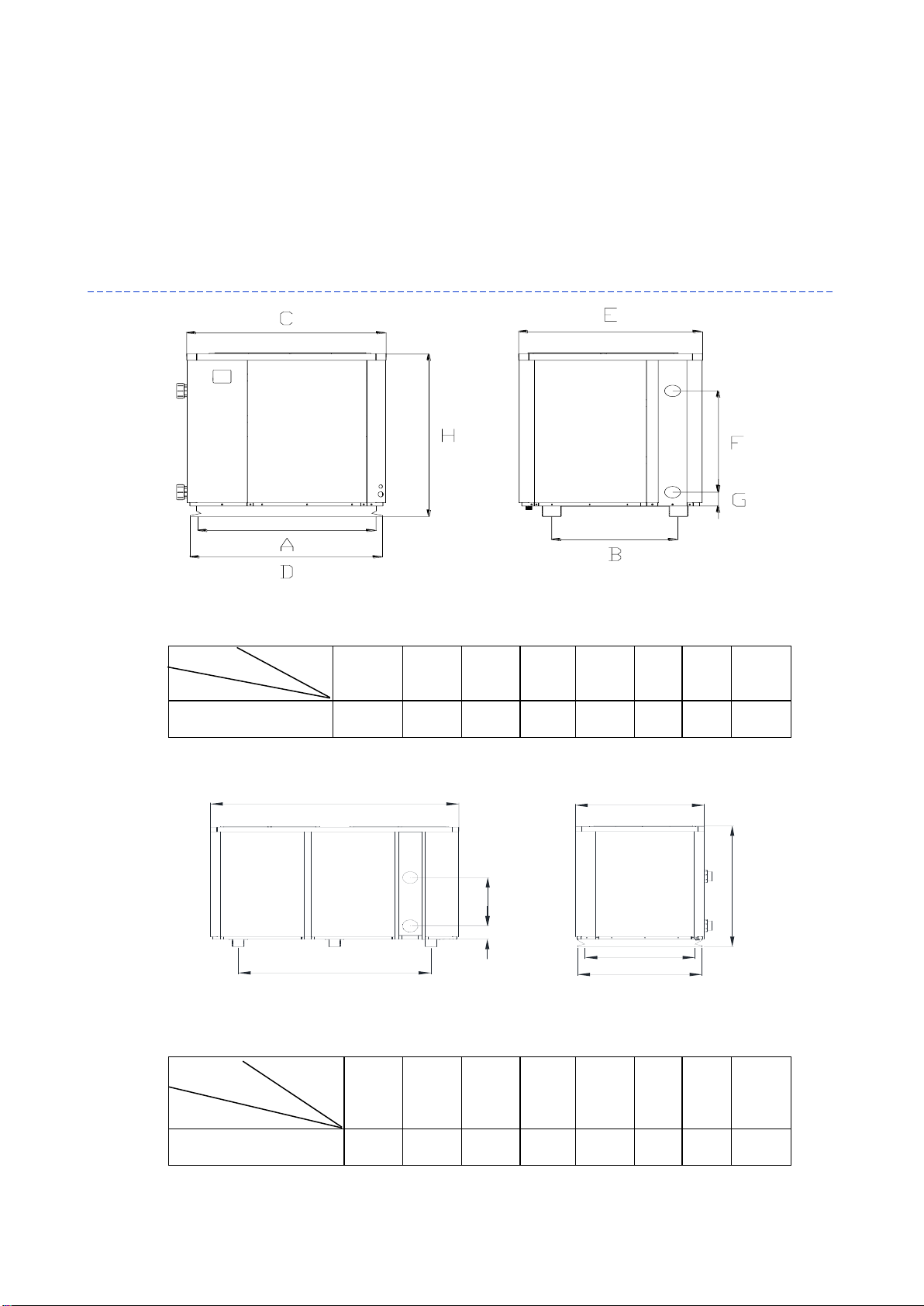
6. Dimension
E
B
F
G
D
A
H
C
A
B
C
D
E
F
G
H
AMHP060
1010
705
1110
1070
1023
780
105
1260
A
B
C
D
E
F
G
H
AMHP090
1010
1630
1090
1050
2100
515
140
1280
Name
Size (mm)
Model
Name
Size (mm)
Model
6
D. Installation guidance
1. Installation reminder
Only a professional staff is allowed to install the heat pump. The users are not qualified to install by
themselves, otherwise the heat pump might be damaged and risky for users’ safety.
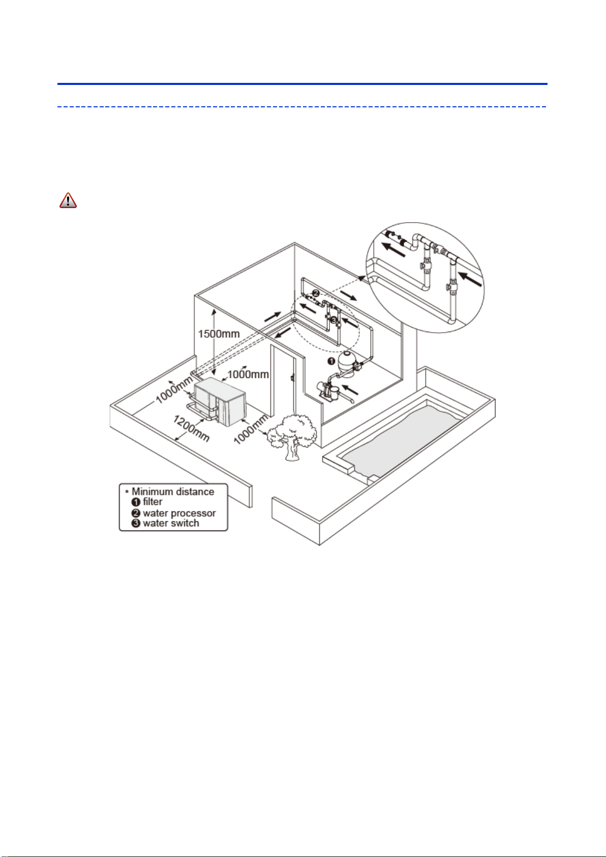
a. Location and water pipe connection
The inverter pool heat pump should be installed in a good ventilation place.
1) The frame must be fixed by bolts (M10) to concrete foundation or brackets. The concrete foundation
must be solid and fastened; the bracket must be strong enough and antirust treated;
2) Please don’t stack substances that will block air flow near inlet or outlet area, and there is no barrier
within 50cm behind the main machine, or the efficiency of the heater will be reduced or even
stopped;
3) The machine needs an appended pump (Supplied by the user). The recommended pump
specification-flux: refer to Technical Parameter, Max. lift ≥10m;
4) When the machine is running, there will be condensation water discharged from the bottom, please
pay attention to it. Please hold the drainage nozzle (accessory) into the hole and clip it well, and then
connect a pipe to drain the condensation water out.

7
b. The inlet and outlet water unions can’t stand the weight of soft pipes. The heat pump must be
connected with hard pipes!
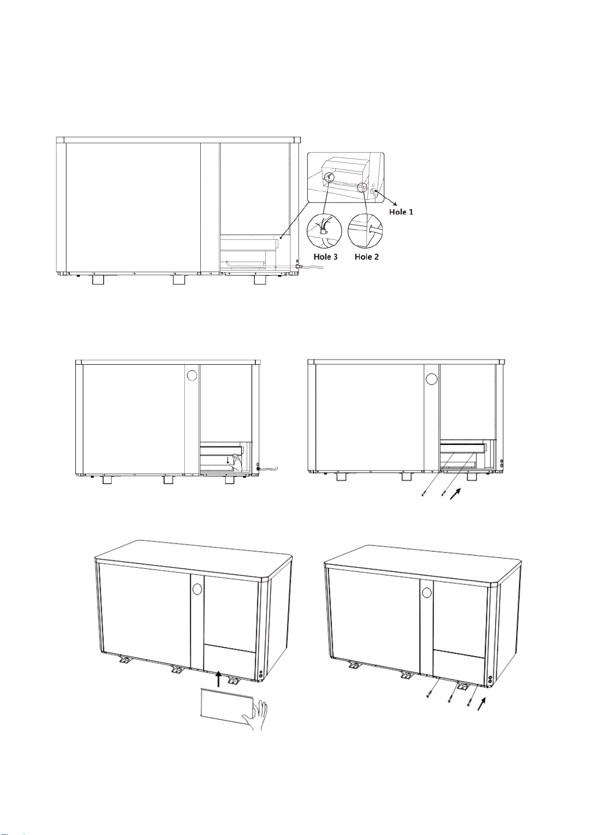
How to connect to the terminal board of IMC60
Step 1. open the maintenance panel
AMHP060
Remove three screws outside
Open the front right panel and the internal
Connect the wire
Restore the internal panel and the front right panel

8
⑤ Fix by screws
AMHP090
Remove three screws outside
Open the panel
Remove two screws inside
Open the internal
9
Step 2. Power cord must be passed through below 3 holes
Connect the wire through three holes
Restore the internal panel
Fix the internal panel by two screws
Restore the panel
Fix the panel by three screws
10
2. Wiring
a. Connect to appropriate power supply, the voltage should comply with the rated voltage of the
products.
b. Earth the machine well.
c. Wiring must be handled by a professional technician according to the circuit diagram.
d. Set leakage protector according to the local code for wiring (leakage operating current ≤ 30mA).
e. The layout of power cable and signal cable should be orderly and not affecting each other.
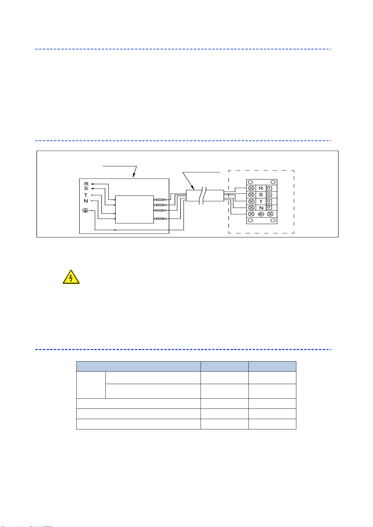
3. Electric wiring Diagram
For power supply: 400V 50Hz
Note: 1) Must be hard wired, plug is not allowed.
2) The swimming pool heat pump must be earthed well.
4. References for protecting devices and cable specification
※ Above data is subject to modification without notice.
Note: The above data is adapted to power cord ≤ 10m. If power cord is>10m, wire diameter must be increased.
The signal cable can be extended to 50m maximumly.
MODEL
AMHP060
AMHP090
Breaker
Maximum Current (A)
23
45
Residual-current circuit breaker
(A)
30
30
Fuse (A)
23
45
Power Cord (mm2)
5x6
5x16
Signal cable (mm2)
3x0.5
3x0.5
Distribution Box(Customer prepare)
Power Cord
Swimming Pool Heat Pump Wiring Board
Power Supply
400V 50Hz
Breaker
Earthing
Fuse

11
E. Operation guidance
1. Key Function
Symbol
Heating & cooling models
i. Power On/Off
ii. Wi-Fi setting
i. Lock/Unlock Screen
ii. Heating mode (18-40°C)
iii. Cooling mode (12-30°C)
iv. Auto mode (12-40°C)
i. Boost
ii. Silence
Temperature Setting
Attention:
i. The controller has power-down memory function.
ii. The buttons will turn dark when it’s locked.
2. Operation Instruction
a. Screen Lock
1) Press for 3 seconds to lock or unlock the screen
2) Automatic Lock Period: 30 seconds if no operation
b. Power On
Press for 3 seconds to unlock screen, Press to power on machine.

12
c. Temperature Setting
Press and to display and adjust set temperature.
d. Mode Selection
1) Heating/Cooling/Auto
Press “ ” to switch among heating ” ”, cooling ” ” and auto mode ” ”.
Heating mode “ ”: Water temperature setting range(18-40°C)
Cooling mode “ ”: Water temperature setting range(12~30°C)
Auto mode “ ”: Water temperature setting range(12~40°C)
* When water inlet temperature is higher than setting point, automatic cooling mode starts.
* When water inlet temperature is lower than setting point, automatic heating mode starts.
2) Silence/Boost mode selection
Press “ ” to switch between boost mode , silence mode
Default mode: boost
Please choose boost mode for initial heating
e. WIFI
When the screen is on, press “ ”for 3 seconds, after “ ” flashing, enter Wi-Fi connection.
Connect Wi-Fi on mobile phone and input password, and then control equipment by Wi-Fi. When
APP connects Wi-Fi successfully,“ ” lights on.
f. Defrosting
1) Automatic defrosting: When machine is auto defrosting, will flash, and return to previous
working mode when it finishes.
2) Manual Defrosting: To enter forced defrosting mode, the compressor must be working more than 10
minutes. in heating mode, press “ ” and “ ” on touch controller simultaneously for 5 seconds
to start forced defrosting, ” ” is flashing and defrost starts, “ ” stop flashing and defrosting stops.
(Remarks: the interval between manual defrosting should be more than 30 minutes.)

13
F. Testing
1. Inspect heat pump before use
a. The ventilating device and outlets are operating adequately and are not obstructed.
b. It’s prohibited to install refrigeration pipe or components in corrosive environment.
c. Inspect the electric wiring on basis of the electric wiring diagram and earthing connection.
d. Double confirm the main machine power switch should be off.
e. Inspect the air inlet and outlet.
2. Trial
a. The user must “Start the Pump before the Machine, and Turn off the Machine before the Pump”, or
the machine will be damaged.
b. Before start the heat pump, please check for any leakage of water.
c. In order to protect the swimming pool heat pump, the machine is equipped with a time lag starting
function, the fan will run 1 minute earlier than the compressor when starting the machine, and it will
stop running 1 minute later than the compressor when power off the machine.
d. After the swimming pool heat pump start up, please kindly checking for any abnormal noise from the
machine.
14
G. Maintenance
1. In winter season when you don’t swim:
a. Cut off power supply to prevent any machine damage.
b. Drain water clear of the machine.
c. Cover the machine body when not in use.
2. Please clean this machine with household detergents or clean water, NEVER use gasoline, thinners
or any similar fuel.
3. Check bolts, cables and connections regularly.
4. If repair or scrap is required, please contact authorized service center nearby.
5. Do not attempt to work on the equipment by yourself. Improper operation may cause danger.
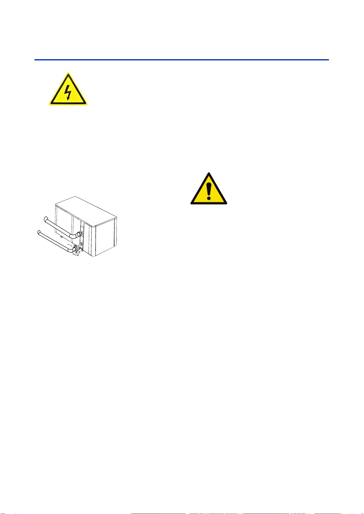
!!Important:
Unscrew the water nozzle of inlet pipe
to let the water flow out.
When the water in machine freezes in winter
season, the titanium heat exchanger may be
damaged.
“CUT OFF” power supply of the heater
before cleaning, examination and repairing

15
H. Trouble shooting for common faults
1. Failure solution and code
----------------------------------------------------------------------------------------------------------------------------------------
Failure
Reason
Solution
Heat pump doesn’t run
No power
Wait until the power recovers
Power switch is off
Switch on the power
Fuse burned
Check and change the fuse
The breaker is off
Check and turn on the
breaker
Fan running but with
insufficient heating
evaporator blocked
Remove the obstacles
Air outlet blocked
Remove the obstacles
3 minutes start delay
Wait patiently
Display normal, but no
heating
Set temp. too low
Set proper heating temp.
3 minutes start delay
Wait patiently
If above solutions don’t work, please contact your installer with detailed information and
your model number. Don’t try to repair it yourself.
Note: If the following conditions happen, please stop the machine immediately, and cut off
the power supply immediately, then contact your dealer:
1.Inaccurate switch action.
2.The fuse is frequently broken or leakage circuit breaker jumped.

16
Protection & Failure code
NO.
Display
Protection code description
1
E3
No water protection
2
E5
Power supply excesses operation range
3
E6
Excessive temp difference between inlet and outlet water(Insufficient
water flow protection)
4
Eb
Ambient temperature too high or too low protection
5
Ed
Anti-freezing reminder
NO.
Display
Failure code description
1
E1
High pressure protection
2
E2
Low pressure protection
3
E4
3 phase sequence protection (three phase only)
4
E7
Water outlet temp too high or too low protection
5
E8
High exhaust temp protection
6
EA
Evaporator overheat protection (only at cooling mode)
7
EC
System communication failure
8
P0
Controller communication failure
9
P1
Water inlet temp sensor failure
10
P2
Water outlet temp sensor failure
11
P3
Gas exhaust temp sensor failure
12
P4
Evaporator coil pipe temp sensor failure
13
P5
Gas return temp sensor failure
14
P6
Cooling coil pipe temp sensor failure
15
P7
Ambient temp sensor failure
16
P8
Cooling plate sensor failure
17
P9
Current sensor failure
18
PA
Restart memory failure
19
F1
Compressor drive module failure
20
F2
PFC module failure
21
F3
Compressor start failure
22
F4
Compressor running failure
23
F5
Inverter board over current protection
24
F6
Inverter board overheat protection
25
F7
Current protection
26
F8
Cooling plate overheat protection
27
F9
Fan motor failure
28
Fb
Power filter plate No-power protection
28
FA
PFC module over current protection
29
FA
PFC module over current protection
30
FC
AC fan motor overcurrent protection
31
Fd
AC fan motor overheat protection
32
FE
AC fan motor phase protection
Notice!
System 1 failure 1 or no display after the error code
System 2 failure 2 is displayed after the error code

17
I. Electrical wiring schematic (optional)
Breaker/fuse
(Customer prepare)
Power Supply
400V~/50Hz
Water pump: 400V voltage
Water Pump
Water Pump
Breaker/fuse
(Customer prepare)
Power Supply
400V~/50Hz
Earthing
Power Cord
coil voltage:400V
Customer remote
control switch
connector
Earthing
Contactor
18
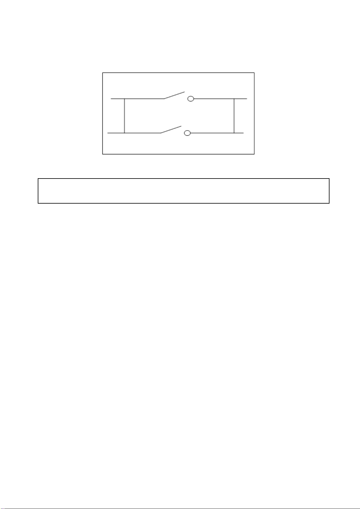
Water pump control and timer connection
1: Water pump timer
2: Water pump wiring of Heat Pump
Note: The installer should connect 1 parallel with 2 (as above picture). To start the water pump, condition
1 or 2 is connected. To stop the water pump, both 1 and 2 should be disconnected.
This manual suits for next models
1
Table of contents
Other atecpool Heat Pump manuals


Popular Heat Pump manuals by other brands

Astral Pool
Astral Pool APH3 INVERBOOST User and service manual

Water Furnace
Water Furnace Envision NRAC026 installation manual

HydroPro
HydroPro 5 User and service manual

Astral Pool
Astral Pool ALASKA Series TECHNICAL MANUAL. START-UP AND OPERATION

alphainnoTec
alphainnoTec SWC - Series operating manual

Mark
Mark HKEU 353 Technical manual

Glowworm
Glowworm Envirosorb 5 Installation and servicing

kensol
kensol HYDROBOX KTH1 Installation and operating instructions

RV Products
RV Products 8535 SERIES Service manual

Daikin
Daikin RXZ25NV1B Service manual

Mareli Systems
Mareli Systems FGS10MB installation manual

Enviritech
Enviritech Heat Pump user manual


