Thermo King CBci 10 12V User manual

CBci & CB MAX
w/Control Box Thermostat
TK 40738-1-MM (Rev. 1, 1/99)
Copyright©1993 Thermo King Corp., Minneapolis, MN, U.S.A.
Printed in U.S.A.

This manual is published for informational purposes only and the information so provided should not be
considered as all-inclusive or covering all contingencies. If further information is required, Thermo King
Corporation should be consulted.
Sale of product shown in this manual is subject to Thermo King’s terms and conditions including, but not
limited to, the THERMO KING EXPRESS WARRANTY. Such terms and conditions are available upon
request.
Thermo King’s warranty will not apply to any equipment which has been “so repaired or altered outside the
manufacturer’s plants as, in the manufacturer's judgment, to effect its stability.”
No warranties, express or implied, including warranties of fitness for a particular purpose or
merchantability, or warranties arising from course of dealing or usage of trade, are made regarding
the information, recommendations, and descriptions contained herein. Manufacturer is not
responsible and will not be held liable in contract or in tort (including negligence) for any special,
indirect or consequential damages, including injury or damage caused to vehicles, contents or
persons, by reason of the installation of any Thermo King product or its mechanical failure.
The maintenance information in this manual covers unit models:
CBci 10 12V (914725) CB MAX 10 12V (915091)
CBci 10 24V (914724) CB MAX 10 24V (915090)
CBci 20 12V (914729) CB MAX 20 12V (915097)
CBci 20 24V (914728) CB MAX 20 24V (915094)
For further information, refer to…
CBci and CB Parts Manual TK 40097
CBci Operating Manual TK 40170
Diagnosing Thermo King Refrigeration System TK 5984
Tool Catalog TK 5955
The information in this manual is provided to assist owners, operators and service people in the proper
upkeep and maintenance of Thermo King units.

Recover Refrigerant
At Thermo King, we recognize the need to preserve the environ-
ment and limit the potential harm to the ozone layer that can
result from allowing refrigerant to escape into the atmosphere.
We strictly adhere to a policy that promotes the recovery and
limits the loss of refrigerant into the atmosphere.
In addition, service personnel must be aware of Federal regula-
tions concerning the use of refrigerants and the certification of
technicians. For additional information on regulations and tech-
nician certification programs, contact your local THERMO KING
dealer.
R-404A and R-134a
CAUTION: Use ONLY Polyol Ester based refrigeration compressor oil (TK P/N
203-413) in R-404A and R-134a units.
DO NOT use Polyol Ester based oil in standard Thermo King units.
DO NOT mix Polyol Ester and standard synthetic compressor oils.
Keep Polyol Ester compressor oil in tightly sealed containers. If Polyol Ester oil
becomes contaminated with moisture or standard oils, dispose of properly—DO NOT
USE!
CAUTION: When servicing Thermo King R-404A and R-134a units, use only those
service tools certified for and dedicated to R-404A and R-134a refrigerant and
Polyol Ester compressor oils. Residual non-HFC refrigerants and non-HFC refrigerants
or oils will contaminate R-404A and R-134a systems.


Table of Contents
Safety Precautions . . . . . . . . . . . . . . . . . . . . . . . . . . . . . . . . . . . . . . . . . . . . . . . . . . . . . . . . . . . . . . . . . . . . . . . . . i
Specifications . . . . . . . . . . . . . . . . . . . . . . . . . . . . . . . . . . . . . . . . . . . . . . . . . . . . . . . . . . . . . . . . . . . . . . . . . . . . .1
Maintenance Inspection Schedule. . . . . . . . . . . . . . . . . . . . . . . . . . . . . . . . . . . . . . . . . . . . . . . . . . . . . . . . . . . . .5
Unit Description. . . . . . . . . . . . . . . . . . . . . . . . . . . . . . . . . . . . . . . . . . . . . . . . . . . . . . . . . . . . . . . . . . . . . . . . . . . .7
Liquid Injection System . . . . . . . . . . . . . . . . . . . . . . . . . . . . . . . . . . . . . . . . . . . . . . . . . . . . . . . . . . . . . . . . . . . . .7
Oil Separator . . . . . . . . . . . . . . . . . . . . . . . . . . . . . . . . . . . . . . . . . . . . . . . . . . . . . . . . . . . . . . . . . . . . . . . . . . . . .8
CBci MAX Features. . . . . . . . . . . . . . . . . . . . . . . . . . . . . . . . . . . . . . . . . . . . . . . . . . . . . . . . . . . . . . . . . . . . . . . .8
Unit Operation . . . . . . . . . . . . . . . . . . . . . . . . . . . . . . . . . . . . . . . . . . . . . . . . . . . . . . . . . . . . . . . . . . . . . . . . . . . .8
Operating Modes. . . . . . . . . . . . . . . . . . . . . . . . . . . . . . . . . . . . . . . . . . . . . . . . . . . . . . . . . . . . . . . . . . . . . . . . . .9
Unit Features. . . . . . . . . . . . . . . . . . . . . . . . . . . . . . . . . . . . . . . . . . . . . . . . . . . . . . . . . . . . . . . . . . . . . . . . . . . .10
Protection Features. . . . . . . . . . . . . . . . . . . . . . . . . . . . . . . . . . . . . . . . . . . . . . . . . . . . . . . . . . . . . . . . . . . . . . .10
Optional Features . . . . . . . . . . . . . . . . . . . . . . . . . . . . . . . . . . . . . . . . . . . . . . . . . . . . . . . . . . . . . . . . . . . . . . . .10
Serial Number Locations. . . . . . . . . . . . . . . . . . . . . . . . . . . . . . . . . . . . . . . . . . . . . . . . . . . . . . . . . . . . . . . . . . .10
Operating Instructions . . . . . . . . . . . . . . . . . . . . . . . . . . . . . . . . . . . . . . . . . . . . . . . . . . . . . . . . . . . . . . . . . . . . .23
Unit Controls . . . . . . . . . . . . . . . . . . . . . . . . . . . . . . . . . . . . . . . . . . . . . . . . . . . . . . . . . . . . . . . . . . . . . . . . . . . .23
Unit Protection Devices. . . . . . . . . . . . . . . . . . . . . . . . . . . . . . . . . . . . . . . . . . . . . . . . . . . . . . . . . . . . . . . . . . . .24
Unit Operation . . . . . . . . . . . . . . . . . . . . . . . . . . . . . . . . . . . . . . . . . . . . . . . . . . . . . . . . . . . . . . . . . . . . . . . . . . .25
Starting the Unit. . . . . . . . . . . . . . . . . . . . . . . . . . . . . . . . . . . . . . . . . . . . . . . . . . . . . . . . . . . . . . . . . . . . . . . . . .25
Adjusting the Thermostat . . . . . . . . . . . . . . . . . . . . . . . . . . . . . . . . . . . . . . . . . . . . . . . . . . . . . . . . . . . . . . . . . .26
After Start Inspection. . . . . . . . . . . . . . . . . . . . . . . . . . . . . . . . . . . . . . . . . . . . . . . . . . . . . . . . . . . . . . . . . . . . . .26
Loading Procedure . . . . . . . . . . . . . . . . . . . . . . . . . . . . . . . . . . . . . . . . . . . . . . . . . . . . . . . . . . . . . . . . . . . . . . .27
Post Loading Procedure . . . . . . . . . . . . . . . . . . . . . . . . . . . . . . . . . . . . . . . . . . . . . . . . . . . . . . . . . . . . . . . . . . .27
Weekly Post Trip Checks . . . . . . . . . . . . . . . . . . . . . . . . . . . . . . . . . . . . . . . . . . . . . . . . . . . . . . . . . . . . . . . . . .27
Electrical Maintenance . . . . . . . . . . . . . . . . . . . . . . . . . . . . . . . . . . . . . . . . . . . . . . . . . . . . . . . . . . . . . . . . . . . . .29
Unit Wiring. . . . . . . . . . . . . . . . . . . . . . . . . . . . . . . . . . . . . . . . . . . . . . . . . . . . . . . . . . . . . . . . . . . . . . . . . . . . . .29
Remote Control Box Components. . . . . . . . . . . . . . . . . . . . . . . . . . . . . . . . . . . . . . . . . . . . . . . . . . . . . . . . . . . .29
Testing the Thermometer . . . . . . . . . . . . . . . . . . . . . . . . . . . . . . . . . . . . . . . . . . . . . . . . . . . . . . . . . . . . . . . . . .29
Testing the Thermostat . . . . . . . . . . . . . . . . . . . . . . . . . . . . . . . . . . . . . . . . . . . . . . . . . . . . . . . . . . . . . . . . . . . .30
Cab Control Box Components (Optional) . . . . . . . . . . . . . . . . . . . . . . . . . . . . . . . . . . . . . . . . . . . . . . . . . . . . . .33
Temperature Control Module (TCM) . . . . . . . . . . . . . . . . . . . . . . . . . . . . . . . . . . . . . . . . . . . . . . . . . . . . . . . . . .33
Defrost System . . . . . . . . . . . . . . . . . . . . . . . . . . . . . . . . . . . . . . . . . . . . . . . . . . . . . . . . . . . . . . . . . . . . . . . . . .36
Engine Operation . . . . . . . . . . . . . . . . . . . . . . . . . . . . . . . . . . . . . . . . . . . . . . . . . . . . . . . . . . . . . . . . . . . . . . . .36
Electric Standby Operation (Model 20 Only). . . . . . . . . . . . . . . . . . . . . . . . . . . . . . . . . . . . . . . . . . . . . . . . . . . .37
Defrost Components . . . . . . . . . . . . . . . . . . . . . . . . . . . . . . . . . . . . . . . . . . . . . . . . . . . . . . . . . . . . . . . . . . . . . .37
Testing the Defrost System. . . . . . . . . . . . . . . . . . . . . . . . . . . . . . . . . . . . . . . . . . . . . . . . . . . . . . . . . . . . . . . . .38
Defrost Timer. . . . . . . . . . . . . . . . . . . . . . . . . . . . . . . . . . . . . . . . . . . . . . . . . . . . . . . . . . . . . . . . . . . . . . . . . . . .40
Circuit Breakers. . . . . . . . . . . . . . . . . . . . . . . . . . . . . . . . . . . . . . . . . . . . . . . . . . . . . . . . . . . . . . . . . . . . . . . . . .42
Condenser Fan Pressure Switch (CFPS) . . . . . . . . . . . . . . . . . . . . . . . . . . . . . . . . . . . . . . . . . . . . . . . . . . . . . .42
Electric Standby Circuits (Model 20 Only). . . . . . . . . . . . . . . . . . . . . . . . . . . . . . . . . . . . . . . . . . . . . . . . . . . . . .43

Table of Contents
Refrigeration Maintenance . . . . . . . . . . . . . . . . . . . . . . . . . . . . . . . . . . . . . . . . . . . . . . . . . . . . . . . . . . . . . . . . . 45
Refrigerant Charge . . . . . . . . . . . . . . . . . . . . . . . . . . . . . . . . . . . . . . . . . . . . . . . . . . . . . . . . . . . . . . . . . . . . . . 45
Charging the Refrigeration System . . . . . . . . . . . . . . . . . . . . . . . . . . . . . . . . . . . . . . . . . . . . . . . . . . . . . . . . . . 45
Checking Compressor Oil Charge . . . . . . . . . . . . . . . . . . . . . . . . . . . . . . . . . . . . . . . . . . . . . . . . . . . . . . . . . . . 47
High Pressure Cutout Switch (HPCO) . . . . . . . . . . . . . . . . . . . . . . . . . . . . . . . . . . . . . . . . . . . . . . . . . . . . . . . . 47
System Cleanup. . . . . . . . . . . . . . . . . . . . . . . . . . . . . . . . . . . . . . . . . . . . . . . . . . . . . . . . . . . . . . . . . . . . . . . . . 48
Refrigerant Hose Routing . . . . . . . . . . . . . . . . . . . . . . . . . . . . . . . . . . . . . . . . . . . . . . . . . . . . . . . . . . . . . . . . . 49
Three-way Valve Condenser Pressure Bypass Check Valve . . . . . . . . . . . . . . . . . . . . . . . . . . . . . . . . . . . . . . 50
Refrigeration Service Operations . . . . . . . . . . . . . . . . . . . . . . . . . . . . . . . . . . . . . . . . . . . . . . . . . . . . . . . . . . . . 51
compressor . . . . . . . . . . . . . . . . . . . . . . . . . . . . . . . . . . . . . . . . . . . . . . . . . . . . . . . . . . . . . . . . . . . . . . . . . . . . 51
Condenser Coil . . . . . . . . . . . . . . . . . . . . . . . . . . . . . . . . . . . . . . . . . . . . . . . . . . . . . . . . . . . . . . . . . . . . . . . . . 51
Filter Drier . . . . . . . . . . . . . . . . . . . . . . . . . . . . . . . . . . . . . . . . . . . . . . . . . . . . . . . . . . . . . . . . . . . . . . . . . . . . . 51
Evaporator Coil . . . . . . . . . . . . . . . . . . . . . . . . . . . . . . . . . . . . . . . . . . . . . . . . . . . . . . . . . . . . . . . . . . . . . . . . . 52
Expansion Valve Assembly . . . . . . . . . . . . . . . . . . . . . . . . . . . . . . . . . . . . . . . . . . . . . . . . . . . . . . . . . . . . . . . . 52
Receiver Tank . . . . . . . . . . . . . . . . . . . . . . . . . . . . . . . . . . . . . . . . . . . . . . . . . . . . . . . . . . . . . . . . . . . . . . . . . . 53
Oil Separator . . . . . . . . . . . . . . . . . . . . . . . . . . . . . . . . . . . . . . . . . . . . . . . . . . . . . . . . . . . . . . . . . . . . . . . . . . . 53
Replacing Refrigerant Hoses. . . . . . . . . . . . . . . . . . . . . . . . . . . . . . . . . . . . . . . . . . . . . . . . . . . . . . . . . . . . . . . 55
Liquid Injection Solenoid Valve . . . . . . . . . . . . . . . . . . . . . . . . . . . . . . . . . . . . . . . . . . . . . . . . . . . . . . . . . . . . . 56
Liquid Injection Metering Orifice. . . . . . . . . . . . . . . . . . . . . . . . . . . . . . . . . . . . . . . . . . . . . . . . . . . . . . . . . . . . . 56
Testing the Liquid Injection Solenoid Valve and Metering Orifice . . . . . . . . . . . . . . . . . . . . . . . . . . . . . . . . . . . 57
High Pressure Cutout And Condenser Fan Switches . . . . . . . . . . . . . . . . . . . . . . . . . . . . . . . . . . . . . . . . . . . . 57
Low Pressure Cutout Switch . . . . . . . . . . . . . . . . . . . . . . . . . . . . . . . . . . . . . . . . . . . . . . . . . . . . . . . . . . . . . . . 57
Suction Pressure Regulator Valve. . . . . . . . . . . . . . . . . . . . . . . . . . . . . . . . . . . . . . . . . . . . . . . . . . . . . . . . . . . 57
Discharge Check Valve Repair (Model 20 Only) . . . . . . . . . . . . . . . . . . . . . . . . . . . . . . . . . . . . . . . . . . . . . . . . 58
Accumulator. . . . . . . . . . . . . . . . . . . . . . . . . . . . . . . . . . . . . . . . . . . . . . . . . . . . . . . . . . . . . . . . . . . . . . . . . . . . 60
Three-way Valve Repair . . . . . . . . . . . . . . . . . . . . . . . . . . . . . . . . . . . . . . . . . . . . . . . . . . . . . . . . . . . . . . . . . . 61
Three-way Valve Condenser Pressure Bypass Check Valve Repair. . . . . . . . . . . . . . . . . . . . . . . . . . . . . . . . . 62
Pilot Solenoid. . . . . . . . . . . . . . . . . . . . . . . . . . . . . . . . . . . . . . . . . . . . . . . . . . . . . . . . . . . . . . . . . . . . . . . . . . . 63
In-line Condenser Check Valve . . . . . . . . . . . . . . . . . . . . . . . . . . . . . . . . . . . . . . . . . . . . . . . . . . . . . . . . . . . . . 63
In-line Condenser Check Valve Replacement . . . . . . . . . . . . . . . . . . . . . . . . . . . . . . . . . . . . . . . . . . . . . . . . . . 64
O-Ring Seal (ORS) Connections . . . . . . . . . . . . . . . . . . . . . . . . . . . . . . . . . . . . . . . . . . . . . . . . . . . . . . . . . . . . 64
Structural Maintenance . . . . . . . . . . . . . . . . . . . . . . . . . . . . . . . . . . . . . . . . . . . . . . . . . . . . . . . . . . . . . . . . . . . . 65
Unit Inspection . . . . . . . . . . . . . . . . . . . . . . . . . . . . . . . . . . . . . . . . . . . . . . . . . . . . . . . . . . . . . . . . . . . . . . . . . . 65
Evaporator Coil . . . . . . . . . . . . . . . . . . . . . . . . . . . . . . . . . . . . . . . . . . . . . . . . . . . . . . . . . . . . . . . . . . . . . . . . . 65
Fan Location . . . . . . . . . . . . . . . . . . . . . . . . . . . . . . . . . . . . . . . . . . . . . . . . . . . . . . . . . . . . . . . . . . . . . . . . . . . 65
Condenser Coil . . . . . . . . . . . . . . . . . . . . . . . . . . . . . . . . . . . . . . . . . . . . . . . . . . . . . . . . . . . . . . . . . . . . . . . . . 66
Unit Mounting Bolts . . . . . . . . . . . . . . . . . . . . . . . . . . . . . . . . . . . . . . . . . . . . . . . . . . . . . . . . . . . . . . . . . . . . . . 66

Table of Contents (Continued)
Compressor and Clutch Maintenance . . . . . . . . . . . . . . . . . . . . . . . . . . . . . . . . . . . . . . . . . . . . . . . . . . . . . . . . .67
Clutch Removal. . . . . . . . . . . . . . . . . . . . . . . . . . . . . . . . . . . . . . . . . . . . . . . . . . . . . . . . . . . . . . . . . . . . . . . . . .67
Clutch Installation . . . . . . . . . . . . . . . . . . . . . . . . . . . . . . . . . . . . . . . . . . . . . . . . . . . . . . . . . . . . . . . . . . . . . . . .69
Shaft Seal Cover and Shaft Seal: Removal and Installation . . . . . . . . . . . . . . . . . . . . . . . . . . . . . . . . . . . . . . . .71
Special Tools. . . . . . . . . . . . . . . . . . . . . . . . . . . . . . . . . . . . . . . . . . . . . . . . . . . . . . . . . . . . . . . . . . . . . . . . . . . .74
System Compressor and Oil . . . . . . . . . . . . . . . . . . . . . . . . . . . . . . . . . . . . . . . . . . . . . . . . . . . . . . . . . . . . . . . .76
Checking the Oil Level . . . . . . . . . . . . . . . . . . . . . . . . . . . . . . . . . . . . . . . . . . . . . . . . . . . . . . . . . . . . . . . . . . . .77
Electrical Connection. . . . . . . . . . . . . . . . . . . . . . . . . . . . . . . . . . . . . . . . . . . . . . . . . . . . . . . . . . . . . . . . . . . . . .77
Clutch Test . . . . . . . . . . . . . . . . . . . . . . . . . . . . . . . . . . . . . . . . . . . . . . . . . . . . . . . . . . . . . . . . . . . . . . . . . . . . .78
Belt Tensions. . . . . . . . . . . . . . . . . . . . . . . . . . . . . . . . . . . . . . . . . . . . . . . . . . . . . . . . . . . . . . . . . . . . . . . . . . . .78
Engine/Compressor Belt and Pulleys . . . . . . . . . . . . . . . . . . . . . . . . . . . . . . . . . . . . . . . . . . . . . . . . . . . . . . . . .78
Over-the-Road Mechanical Diagnosis . . . . . . . . . . . . . . . . . . . . . . . . . . . . . . . . . . . . . . . . . . . . . . . . . . . . . . . . .79
Electric Standby Mechanical Diagnosis . . . . . . . . . . . . . . . . . . . . . . . . . . . . . . . . . . . . . . . . . . . . . . . . . . . . . . .81
Refrigeration Diagnosis . . . . . . . . . . . . . . . . . . . . . . . . . . . . . . . . . . . . . . . . . . . . . . . . . . . . . . . . . . . . . . . . . . . .85
Wiring and Schematic Diagrams Index . . . . . . . . . . . . . . . . . . . . . . . . . . . . . . . . . . . . . . . . . . . . . . . . . . . . . . . .87


i
Safety Precautions
GENERAL PRACTICES
1. ALWAYS WEAR GOGGLES OR SAFETY
GLASSES. Refrigerant liquid, refrigeration oil, and
battery acid can permanently damage the eyes (see First
Aid under Refrigeration Oil).
2. Never operate the unit with the compressor discharge
valve closed.
3. Keep your hands, clothing and tools clear of the fans
and belts when the unit is running. This should also be
considered when opening and closing the compressor
service valves.
4. Make sure gauge manifold hoses are in good condition.
Never let them come in contact with a belt, fan motor
pulley, or any hot surface.
5. Never apply heat to a sealed refrigeration system or
container.
6. Fluorocarbon refrigerants, in the presence of an open
flame or electrical short, produce toxic gases that are
severe respiratory irritants capable of causing death.
7. Make sure all mounting bolts are tight and are of cor-
rect length for their particular application.
8. Use extreme caution when drilling holes in the unit.
The holes may weaken structural components, and
holes drilled into electrical wiring can cause fire or
explosion.
9. Use caution when working around exposed coil fins.
The fins can cause painful lacerations.
10. Use caution when working with a refrigerant or refrig-
eration system in any closed or confined area with a
limited air supply (for example, a truck box or garage).
Refrigerant tends to displace air and can cause oxygen
depletion resulting in suffocation and possible death.
11. In the USA, EPA Section 608 Certification is needed to
work on refrigeration systems.
REFRIGERANT
Although fluorocarbon refrigerants are classified as safe
refrigerants, certain precautions must be observed when
handling them or servicing a unit in which they are used.
When exposed to the atmosphere from the liquid state, fluo-
rocarbon refrigerants evaporator rapidly, freezing anything
they contact.
First Aid
In the event of frost bite, the objectives of First Aid are to
protect the frozen area from further injury, to warm the
affected area rapidly and to maintain respiration.
• EYES: For contact with liquid, immediately flush eyes
with large amounts of water and get prompt medical
attention.
• SKIN: Flush area with large amounts of lukewarm
water. Do not apply heat. Remove contaminated cloth-
ing and shoes. Wrap burns with dry, sterile, bulky
dressing to protect from infection/injury. Get medical
attention. Wash contaminated clothing before reuse.
• INHALATION: Move victim to fresh air and use CPR
if necessary. Stay with victim until arrival of emer-
gency medical personnel.
REFRIGERATION OIL
Avoid refrigeration oil contact with the eyes. Avoid pro-
longed or repeated contact of refrigeration oil with skin or
clothing. Wash thoroughly after handling refrigeration oil to
prevent irritation.
First Aid
In case of eye contact, immediately flush with plenty of
water for at least 15 minutes. Wash skin with soap and
water. CALL A PHYSICIAN.

Safety Precautions (Rev. 1/99)
ii
ELECTRICAL HAZARDS
High Voltage
When servicing or repairing a refrigeration unit, the possi-
bility of serious or even fatal injury from electrical shock
exists. Extreme care must be used when working with an
operating refrigeration unit. Lethal voltage potentials can
exist on connections in the high voltage tray of the control
box.
Precautions
1. When working on high voltage circuits on the refrigera-
tion unit, do not make any rapid moves. If a tool drops,
do not grab for it. People do not contact high voltage
wires on purpose. It occurs from an unplanned move-
ment.
2. Use tools with insulated handles that are in good condi-
tion. Never hold metal tools in your hand if exposed,
energized conductors are within reach.
3. Treat all wires and connections as high voltage until a
meter and wiring diagram show otherwise.
4. Never work alone on high voltage circuits on the refrig-
eration unit, another person should always be standing
by in the event of an accident to shut off the refrigera-
tion unit and to aid a victim.
5. Have electrically insulated gloves, cable cutters and
safety glasses available in the immediate vicinity in the
event of an accident.
First Aid
IMMEDIATE action must be initiated after a person has
received an electrical shock. Obtain immediate medical
assistance if available.
The source of shock must be immediately removed by
either shutting down the power or removing the victim from
the source. If it is not possible to shut off the power, the wire
should be cut with either an insulated instrument (e.g., a
wooden handled axe or cable cutters with heavy insulated
handles) or by a rescuer wearing electrically insulated
gloves and safety glasses. Whichever method is used do not
look at the wire while it is being cut. The ensuing flash can
cause burns and blindness.
If the victim has to be removed from a live circuit, pull the
victim off with a non-conductive material. Use the victim’s
coat, a rope, wood, or loop your belt around the victim’s leg
or arm and pull the victim off. DO NOT TOUCH the victim.
You can receive a shock from current flowing through the
victim’s body. After separating the victim from power
source, check immediately for the presence of a pulse and
respiration. If a pulse is not present, start CPR (Cardio Pul-
monary Resuscitation) and call for emergency medical
assistance. If a pulse is present, respiration may be restored
by using mouth-to-mouth resuscitation, but call for emer-
gency medical assistance.
Low Voltage
Control circuits used in the refrigeration unit are low volt-
age (12 volts dc). This voltage potential is not considered
dangerous, but the large amount of current available (over
30 amperes) can cause severe burns if shorted or ground.
Do not wear jewelry, watch or rings. These items can short
out electrical circuits and cause severe burns to the wearer.

1
Specifications
R-134a REFRIGERATION SYSTEM
Compressor Zexel DKS-15CH
Engine Compressor Oil Charge 11.5 oz (339 ml)
Electric Standby Compressor Oil Charge 5.7 oz (168 ml)
Compressor Oil Type Polyol Ester P/N 203-413
Refrigerant Type R-134a
Defrost Method: Truck Engine Operation: CBci210 MAX Hot gas
CBci220 MAX Hot gas
Electric Standby: CBci220 MAX Hot gas and optional electric heaters
Defrost Termination Switch: Opens 52 F (11.1 C)
Closes 42 F (5.6 C)
High Temperature Switch: Opens 200 ± 5 F (39 ± 3 C)
Closes 230 ± 5 F (110 ± 3 C)
High Pressure Cutout Switch:Opens 300 ± 25 psi (2068 ± 68 kPa)
Closes 200 ± 20 psi (3103 ± 138 kPa)
Low Pressure Cutout Switch: Opens 5 to 11 in. Hg vacuum (-17 to -37 kPa)
Closes 4 to 7 psi (28 to 48 kPa)
Condenser Pressure Fan Switch:Opens 130 ± 10 psi (896 ± 69 kPa)
Closes 180 ± 10 psi (1241 ± 69 kPa)
Suction Pressure Regulator Setting 18 psi (124 kPa)
Defrost Timer: Initiation Interval 4 hours
Termination Interval 45 minutes
R-404A REFRIGERATION SYSTEM
Compressor Zexel DKS-15CH
Engine Compressor Oil Charge 11.5 oz (339 ml)
Electric Standby Compressor Oil Charge 5.7 oz (168 ml)
Compressor Oil Type Polyol Ester P/N 203-413
Refrigerant Type R-404A
Defrost Method: Truck Engine Operation: CBci210 Hot gas
CBci220 Hot gas
Electric Standby: CBci220 Hot gas and optional electric heaters
Defrost Termination Switch: Opens 52 F (11.1 C)
Closes 42 F (5.6 C)
High Temperature Switch: Opens 200 ± 5 F (39 ± 3 C)
Closes 230 ± 5 F (110 ± 3 C)
High Pressure Cutout Switch:Opens 470 ± 7 psi (3241 ± 48 kPa)
Closes 375 ± 38 psi (2586 ± 138 kPa)
Low Pressure Cutout Switch: Opens 5 to 11 in. Hg vacuum (-17 to -37 kPa)
Closes 4 to 7 psi (28 to 48 kPa)

Specifications (Rev. 1/99)
2
R-404A REFRIGERATION SYSTEM (continued)
Condenser Pressure Fan Switch:Opens 130 ± 10 psi (896 ± 69 kPa)
Closes 180 ± 10 psi (1241 ± 69 kPa)
Suction Pressure Regulator Setting 18 psi (124 kPa)
Defrost Timer: Intuition Interval 4 hours
Termination Interval 45 minutes
ELECTRICAL SYSTEM
Circuit Breaker Ratings
12 Vdc 40 amp manual reset
24 Vdc 25 amp manual reset
Condenser and Evaporator Fan Motors
Voltage Horsepower Power Rating in
Kilowatts rpm Full Load Current
12 Vdc 0.17 0.12 1850 to 2250 8.0 to 14.5 amps
24 Vdc 0.1 0.12 1850 to 2250 4.2 to 7.8 amps
Pilot Solenoid and Liquid Injection Solenoid Coils
Voltage Current Resistance
12 Vdc 0.6 to 0.8 amps 15 to 19 ohms
24 Vdc 0.3 to 0.4 amps 62 to 72 ohms
Electric Standby Compressor Motors
Voltage Phase Frequency Horsepower Power Rating
in Kilowatts Full Load
rpm Full Load
Current
230 Vac 1 60 Hz 3 2.2 1755 12.4 amps
220 Vac 1 50 Hz 2.5 1.9 1470 11.0 amps
230 Vac* 3 60 Hz 3 2.2 1750 9.8 amps
460 Vac* 3 60 Hz 3 2.2 1750 4.9 amps
380 Vac* 3 50 Hz 2.5 1.9 1420 5.0 amps
380 Vac 3 50 Hz 3 2.2 1420 5.2 amps
415 Vac 3 50 Hz 3 2.2 1420 4.7 amps
*Motor can be wired for all three voltages.
Specifications (Rev. 1/99)
3
Optional Electric Heaters
Voltage Power Rating
Watts Current Resistance
230 Vac 800 3.48 amps 66.1 ohms
380 Vac 800 2.1 amps 180.5 ohms
BELT TENSION (Using Tool P/N 204-427)
Field Reset
Engine/Compressor 35
Electric Motor/Compressor 58

4

5
Maintenance Inspection Schedule
First Week Inspection and Maintenance
After First Week of operation:
•Check the belt tension
•Tighten the unit mounting bolts
•Check the refrigerant level
•Check the compressor oil level
Weekly Monthly Bi-
monthly Annually Inspect/Service These Items
ELECTRICAL
••
Check defrost initiation and termination.
••
Check thermostat cycle sequence.
••
Check operation of protection shutdown circuits.
••
Check thermostat and thermometer calibration in 32 F (0 C)
ice-water bath
••
Inspect wire harness for damaged wires or connections.
•Inspect/replace dc fan motor brushes yearly.
REFRIGERATION
••• •
Check refrigerant level.
•• •
Check compressor oil level.
•Replace dehydrator.
STRUCTURAL
••• •
Visually inspect unit and refrigerant hoses for fluid leaks.
••• •
Visually inspect unit for damaged, loose or broken parts.
••• •
Clean defrost drains.
•• •
Inspect belts (CBci220) for condition and proper tension (belt
tension tool P/N 204-427).
•• •
Clean entire unit including evaporator coil and condenser coil.
••
Check all unit mounting bolts, brackets, lines, hoses, etc.

6

7
Unit Description
The Thermo King CBci truck refrigeration system is a
three-piece system consisting of a condenser, an evaporator,
and a compressor. The assemblies are separate, and the con-
denser section can be installed either in a nosemount or an
undermount position. The evaporator mounts on the inside
of the front wall of the truck body close to the ceiling. The
compressor is mounted on and driven by the truck engine.
Refrigeration hoses or lines are used to connect the con-
denser, the evaporator and the compressor. Model 20 units
have another compressor and an electric motor mounted in
the condenser section for electric standby operation.
The units are designed for low and medium temperature
applications on medium-sized trucks. There are two basic
models:
•Model 10: Cool and defrost on engine-driven compres-
sor operation.
•Model 20: Cool and defrost on both truck engine-
driven and electric standby compressor operation.
The control circuits operate on 12 or 24 Vdc supplied by the
truck batteries for over-the-road operation. On standby
operation, the power is rectified from an AC transformer.
The refrigeration system is protected by a high pressure cut-
out switch and a low pressure cutout switch.
The remote control box is normally mounted on the truck
body. It contains the On-Off switch, manual defrost switch,
thermometer, thermostat, and indicator lights. The remote
control box cover must be opened to access the thermostat.
An optional cab control box is available. It is mounted in the
truck cab and replaces the remote control box. The cab con-
trol box contains the On-Off switch, Manual Defrost switch,
thermometer, thermostat, and indicator lights. The Model 20
cab control box also has a warning light that illuminates if
the driver starts the truck engine while the electric standby
cord is still plugged into the power receptacle.
The electric standby compressor is connected in parallel
with the engine-driven compressor on the Model 20 units.
The engine compressor is driven by a belt from the engine.
The standby compressor is mounted in the condenser sec-
tion and is belt driven by an electric motor. Both compres-
sors use the same refrigeration system circuit. Check valves
isolate one compressor from the other during operation.
Compressor operation is controlled by the thermostat, start-
ing the motor on electric standby or energizing the clutch
during engine operation.
Selection of engine operation or standby operation is auto-
matic on Model 20 units. When the Model 20 unit is
plugged into standby power, engine operation is automati-
cally locked out. If the driver turns the truck on while the
power cord is still plugged into a power receptacle, the
power cord warning light (Model 20 only) comes on to
remind the driver to unplug the cord. The engine driven
compressor cannot be started until the power cord is
unplugged from the unit.
A three-way valve refrigeration system provides defrost in
the unit. An electronic defrost timer can initiate defrost
automatically. Defrost is normally terminated by the defrost
termination switch mounted on the evaporator coil, but the
defrost timer can also terminate defrost.
Liquid Injection System
If the discharge gas leaving the engine driven compressor
reaches a temperature of 230 ± 5 F (110 ± 3 C), the high
temperature switch closes, providing voltage to the liquid
injection solenoid. The solenoid opens a valve, allowing liq-
uid refrigerant to flow from the liquid line near the receiver
outlet valve to the metering orifice attached to the suction
fitting at the compressor. As the refrigerant passes through
the metering orifice it expands and evaporates, cooling the
suction gas entering the compressor. This cooling effect is
transferred to the discharge gas leaving the compressor from

Unit Description (Rev. 1/99)
8
the adjacent cavity in the compressor head. When the dis-
charge gas is cooled to 200 ± 5 F (93 ± 3 C), the high tem-
perature switch opens, the liquid injection solenoid valve
closes and refrigerant no longer flows through the liquid
injection system.
Oil Separator
An oil separator is a standard feature. It separates compres-
sor oil from refrigerant vapor and returns the oil to the com-
pressor through the oil fill hole by using a special adapter.
The oil separator helps provide positive oil return at high
compressor speeds and low operating temperatures. This
feature enhances compressor lubrication and extends com-
pressor life.
CBci MAX Features
The CBci MAX is functionally the same as CBci units, but
it uses R-404A refrigerant. This unit has a redesigned evap-
orator in order to operate more efficiently with R-404A
refrigerant. All other operating features are the same as
CBci units.
UNIT OPERATION
These units shift between cool, null, and heat (optional) to
maintain the box temperature at the thermostat setpoint. The
operating modes are: cool, null, heat (optional), and defrost.
The thermostat controls the operation of the unit by energiz-
ing and de-energizing the cool relay and the heat relay.
When the cool relay is energized, it closes contacts that
energize the fan relay and the compressor clutch (or the
compressor motor contactor on Model 20 units during elec-
tric standby operation).
When the heat relay is energized, it closes contacts that
energize the fan relay.
When the fan relay is energized, it closes contacts that ener-
gize the condenser and evaporator fans. The condenser fan
is also controlled by the condenser fan pressure switch. This
normally open switch monitors the compressor discharge
pressure. When the discharge pressure rises to 180 ± 10 psi
(1241 ± 69 kPa), the switch closes and energizes the con-
denser fan. When the discharge pressure drops to 130 ± 10
psi (896 ± 69 kPa), the switch opens and de-energizes the
condenser fan.
Cool
The thermostat energizes the cool relay at box temperatures
above setpoint when the temperature is dropping. The ther-
mostat energizes the cool relay at box temperatures more
than 2 ± 1 F (1 ± 0.5 C) above setpoint when the tempera-
ture is rising. The cool relay energizes the fan relay and the
compressor clutch (or motor contactor). The fans and the
compressor run and the unit cools.
Null
The thermostat de-energizes the cool relay and the heat
relay at box temperatures between setpoint and 2 ± 1 F (1 ±
0.5 C) below setpoint when the temperature is dropping.
The thermostat de-energizes the cool relay and the heat
relay at box temperatures between setpoint and 2 ± 1 F (1 ±
0.5 C) above setpoint when the temperature is rising. When
the cool relay and the heat relay are both de-energized, the
unit does not operate unless it is in defrost.
Heat (Optional)
NOTE: Heat lockout occurs at setpoints of 15 F (-9.5 C)
and lower. Heat lockout disables Heat and replaces Heat
with Null.
The thermostat energizes the heat relay at box temperatures
more than 2 ± 1 F (1 ± 0.5 C) below setpoint when the tem-
perature is dropping. The thermostat energizes the heat
relay at box temperatures below setpoint when the tempera-
ture is rising. The heat relay energizes the fan relay, but the
compressor clutch (or motor contactor) is not energized.
Therefore, the evaporator fans run but the condenser fan
Unit Description (Rev. 1/99)
9
does not. The heat relay also energizes the optional water
pump and hot water valve, or the optional heater contactor.
Defrost
The defrost cycle can be initiated any time the evaporator
coil temperature is below 42 F (5.6 C). Defrost is initiated
automatically by the defrost timer, or manually by pressing
the Manual Defrost switch.
The defrost relay energizes the compressor clutch (or motor
contactor) and the 26 circuit to route hot refrigerant gas to
the evaporator. The defrost relay also interrupts power to the
fan relay to stop the evaporator and condenser fans during
defrost. The defrost cycle will continue until the evaporator
coil temperature rises to 52 F (11.1 C), causing the defrost
termination switch to open, which terminates the defrost
cycle. If the defrost termination switch does not open in less
than 45 minutes, the defrost timer will terminate the defrost
cycle 45 minutes after is was started.
OPERATING MODES
•Cool—Above setpoint when the temperature is drop-
ping. More than 2 ± 1 F (1 ± 0.5 C) above setpoint
when the temperature is rising.
•Null—Between setpoint and 2 ± 1 F (1 ± 0.5 C) below
setpoint when the temperature is dropping. Between
setpoint and 2 ± 1 F (1 ± 0.5 C) above setpoint when
the temperature is rising.
•Heat—More than 2 ± 1 F (1 ± 0.5 C) below setpoint
when the temperature is dropping. Below setpoint when
the temperature is rising (optional).
•Defrost—Initiated manually or automatically at evapo-
rator temperatures below 42 F (5.6 C). Terminated
when the evaporator temperature rises to 52 F (11.1 C),
or 45 minutes after initiated.
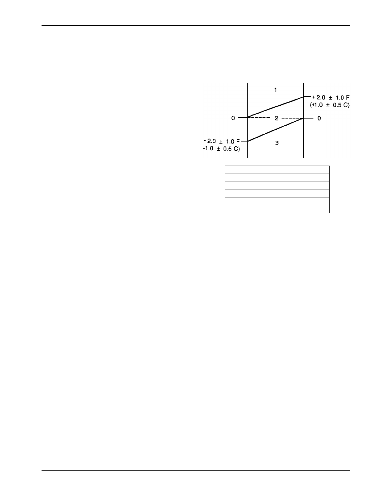
0. Setpoint
1. Cool
2. Null
3. Heat* (Optional)
*Heat lockout occurs at setpoints of
15 F (-9.5 C) or lower.
Thermostat Algorithm
AGA301

Unit Description (Rev. 1/99)
10
UNIT FEATURES
•Digital Thermometer
•Electronic Thermostat
•Defrost Timer
•Hot Gas Defrost
•Defrost Termination Switch
•Liquid Injection System
•Manual Defrost Switch
•Receiver Tank with Outlet Service Valve
•Suction Pressure Regulator
•Oil Separator
•Compressor Powered by Truck Engine
•Three-way Valve Refrigeration System
•Accumulator Tank
•Standby Compressor (Model 20 only)
•Refrigerant Flow Controlled by Discharge Check Valve
(Model 20 only)
PROTECTION FEATURES
•Control Circuit Breaker(s):
40 amp auto reset in 12 Vdc system
•Refrigerant High Pressure Cutout
•Refrigerant Low Pressure Cutout
•Refrigerant High Pressure Relief Valve
•Power Cord Warning Light (in Optional Cab Control
Box for Model 20 only)
•Overload Relay Protection for Electric Standby Motor
(Model 20 only)
•Transformer Fuses (Model 20 only)
OPTIONAL FEATURES
•Cab Control Box
•Refrigerant R-134a
•Electric Motors (Model 20 only)
230 Volt/1 Phase/60 Hz
220 Volt/1 Phase/50 Hz
230 Volt/3 Phase/60 Hz
460 Volt/3 Phase/60 Hz
380 Volt/3 Phase/50Hz
415 Volt/3 Phase/50 Hz
•Heat, Truck Engine (Model 10)
•Heat, Truck Engine and Electric Standby Heater Strips
(Model 20)
•Paint, Special Color
SERIAL NUMBER LOCATIONS
Condenser: Roadside, top corner.
Evaporator: Roadside panel.
Compressor: Nameplate on compressor body.
Standby Motor: Nameplate on motor.
This manual suits for next models
14
Table of contents
Other Thermo King Thermostat manuals

Popular Thermostat manuals by other brands


Daikin
Daikin One+ Homeowner's guide

elsner elektronik
elsner elektronik KNX Touch One Style Technical specifications and installation instructions

DELTA DORE
DELTA DORE TYBOX user guide

LK Systems
LK Systems S2 Assembly instructions

Vimar
Vimar 2950 instruction manual

Systems Controls & Instruments
Systems Controls & Instruments ERV-24-Super Quick start and wiring instruction for installers