Thermo Scientific FISHER HAMILTON MAX/WALL User manual


MAX/Wall®Technical Wall System
2
Component Identification
Ceiling Facing Insert
Options:
Glazed
Steel
Fabric
Open (Ceiling Trim Kit)
Corner
Upper Facing Insert
Options:
Glazed
Steel
Fabric
Open (Ledge Cap Only)
Reagent Facing Insert
Lower Facing Inserts
Frame Assembly
Ledge Cap:
HPL, Chemsurf,
Epoxy or Steel
End
Closure
Panel
Extension:
7'-9" to 9'-3"
8'-9" to 10'-3"
Reinforcement Channel
(for attachment to suspended
ceiling) Select 24" or 48"
Ceiling Channel
Riser Plug
Center
Shelf

MAX/Wall®Technical Wall System
3
Table of Contents
Component Identification . . . . . . . . . . . . . . . . . . . . . . . . . . . . . . . . . . . . . . . 4
Section 1 – Introduction . . . . . . . . . . . . . . . . . . . . . . . . . . . . . . . . . . . . . 5–10
1.1 Preparation for Installation . . . . . . . . . . . . . . . . . . . . . . . . . . . . . 4
1.2 Material Handling . . . . . . . . . . . . . . . . . . . . . . . . . . . . . . . . . . . . 5
1.3 Assembly Guidelines . . . . . . . . . . . . . . . . . . . . . . . . . . . . . . 6–10
Section 2 – Receiving Procedures . . . . . . . . . . . . . . . . . . . . . . . . . . . . 11–15
2.1 Receiving and Identifying Fisher Hamilton Product . . . . . . . 11–13
2.2 Receiving/Damage . . . . . . . . . . . . . . . . . . . . . . . . . . . . . . . . . . 14
2.3 Unloading . . . . . . . . . . . . . . . . . . . . . . . . . . . . . . . . . . . . . . . . . 15
2.4 Phone Calls . . . . . . . . . . . . . . . . . . . . . . . . . . . . . . . . . . . . . . . 15
2.5 Delivery Schedule . . . . . . . . . . . . . . . . . . . . . . . . . . . . . . . . . . . 15
2.6 Receiving Purchased Items . . . . . . . . . . . . . . . . . . . . . . . . . . . 15
Section 3 – Installing Wall Frames . . . . . . . . . . . . . . . . . . . . . . . . . . . 16–33
3.1 Overview of Anchoring the Walls to the Ceiling . . . . . . . . . . 16–17
3.2 Overview of Anchoring Cabinet Supported Walls . . . . . . . . . . . . 17
3.3 Overview of Constructing Free-Standing Units . . . . . . . . . . . . . 18
3.4 Anchoring Wall Frames to Floor . . . . . . . . . . . . . . . . . . . . . 19–20
3.5 End Closure Panels . . . . . . . . . . . . . . . . . . . . . . . . . . . . . . 21–22
3.6 Joining Wall Frames . . . . . . . . . . . . . . . . . . . . . . . . . . . . . . . . . 22
3.7 Base Molding . . . . . . . . . . . . . . . . . . . . . . . . . . . . . . . . . . . . . . 23
3.8 Corner Filler – Two-Way . . . . . . . . . . . . . . . . . . . . . . . . . . . 24–25
3.9 Corner Filler – Three- and Four-Way Connector/Fillers . . . . . 26–27
3.10 Service Chase . . . . . . . . . . . . . . . . . . . . . . . . . . . . . . . . . . . . . 28
3.11 Door Frame . . . . . . . . . . . . . . . . . . . . . . . . . . . . . . . . . . . . . . . 29
3.12 Ceiling Facing Inserts, Steel . . . . . . . . . . . . . . . . . . . . . . . . . . . 30
3.13 Ceiling Facing Inserts, Fabric . . . . . . . . . . . . . . . . . . . . . . . . . . 30
3.14 Lower Facing Inserts, Steel . . . . . . . . . . . . . . . . . . . . . . . . . . . 31
3.15 Upper Facing Panels, Steel or Fabric . . . . . . . . . . . . . . . . . . . . . 31
3.16 Ceiling Connector Trim . . . . . . . . . . . . . . . . . . . . . . . . . . . . . . . 32
3.17 Ledge Cap . . . . . . . . . . . . . . . . . . . . . . . . . . . . . . . . . . . . . . . . 32
3.18 Glass Inserts . . . . . . . . . . . . . . . . . . . . . . . . . . . . . . . . . . . . . . 33
Section 4 – Installing Supporting Furniture and Casework . . . . . . . . . . 34–57
4.1 Vertical Utility Service Raceway . . . . . . . . . . . . . . . . . . . . . . . . 34
4.2 Cantilever Table to Wall Frame . . . . . . . . . . . . . . . . . . . . . . 35–36
4.3 Cantilever Corner Work Surface, 90 Degrees, to Wall Frame 37–40
4.4 Structural Corner Table, 90 Degrees, to Wall Frame . . . . . . . . . 41
4.5 Corner Table Support for Cantilever Work Surface or
Structural Table . . . . . . . . . . . . . . . . . . . . . . . . . . . . . . . . . 42–43
4.6 Support Leg to the Cantilever Table . . . . . . . . . . . . . . . . . . . . . 44
4.7 General Purpose Shelves . . . . . . . . . . . . . . . . . . . . . . . . . . . . . 45
4.8 Inner Shelves to the Wall Frame . . . . . . . . . . . . . . . . . . . . . . . . 46
4.9 Sloping Adjustable Shelf to the Wall Frame . . . . . . . . . . . . . . . . 47
4.10 Floor and Wall Mounted Cabinets . . . . . . . . . . . . . . . . . . . . 48–51
4.11 Installing Upper Cabinets to a Wall Frame . . . . . . . . . . . . . . . . . 52
4.12 Suspended Cabinets . . . . . . . . . . . . . . . . . . . . . . . . . . . . . . 53–54
4.13 520H Series Drawer Units to a Table . . . . . . . . . . . . . . . . . . . . 55
4.14 Reference/Pencil Drawer . . . . . . . . . . . . . . . . . . . . . . . . . . . . . 56
4.15 Pullboard . . . . . . . . . . . . . . . . . . . . . . . . . . . . . . . . . . . . . . . . . 57

MAX/Wall®Technical Wall System
4
Section 1 – Introduction
Tools Required:
3/8" Drive socket set, including the following:
Extension (2" or 3")
Universal joint
Hex bits (4" long min.) - 3/16", 5/16".
Combination wrenches - 3/8", 3/16", 1/2", 9/16".
Phillips screwdrivers - (#2 and #3 tips)
1/2" drill motor (Hammer drill preferable)
1/2" masonry drill bit
Torque wrench
Rubber mallet
Jigsaw with metal cutting blade
Chalk line
Carpenter’s level (4' min.)
Facing insert removal tool
Flat blade screwdriver
Hammer
Knife
Measuring tape
Optional Tools to speed installation:
Drill motor or cordless drill including: set of drill bits
(specifically #12 or 3/16")
1/2" hex shank (2-1/2" long)
2 C-clamps (4" min. throat depth)
Masking tape
This manual is intended as a procedural tool for the
installation and assembly of Fisher Hamilton furni-
ture. It also serves as an aid to designers and plan-
ners during layout and cost analysis, and to facility
managers to carry out periodic modifications.
Disclaimer and Warning:
Fisher Hamilton disclaims liability for installations
(including re-arrangements and additions) not in
strict conformity with the instructions contained here-
in or with other written instruction of Fisher Hamilton.
Fisher Hamilton further disclaims liability if its
products are modified, altered, abused or misused.
1.1 Preparation for Installation
1. Select a staging area as close to the installation
as possible. If more than one floor is involved,
provide a staging area for each floor.
2. Check actual floor dimensions against the layout
print for possible un-planned obstructions. These
could include walls, columns, service entrances,
or changes in floor elevation such as slopes or
steps.
3. Mark the proposed layout on the floor with mask-
ing or a chalk line. Find and mark the high spot on
the floor by sliding a four foot carpenter’s level
across the floor.
4. Start the installation of each run at a corner near-
est the high point and adjust the leveler out 1-1/4"
at that point. Caution: Support structures must be
1-1/4" minimum off the floor to provide adequate
clearance for power cables and installation of
supported structural table.
Caution: Support structures must be 1-1/4" mini-
mum off the floor to provide adequate clearance
for power cables and installation of supported
structural table.
5. If possible, start the installation at the farthest
point from the staging area to avoid hauling prod-
ucts through areas already installed.
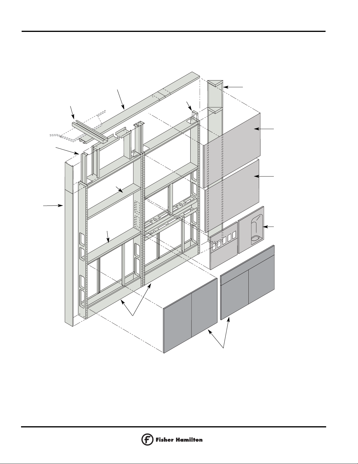
6. Installation sequence:
a. Assemble the panels and cores per to floor
plan,
making sure adequate support is provided to
stabilize the configuration.
If structural tables are to be installed, they
should, whenever possible, be attached to
individual panels before assembling panels into
runs.
b. Install the appropriate wiring, and plumbing.
c. Attach the base covers and facing inserts.
d. Install cantilevered work surfaces, upper and
lower storage, and other accessories.
e. Move primary tables and any other free-
standing furniture into place.
7. To avoid soiling the fabric on fabric covered
facing inserts, handling them with white cotton
gloves is recommended.
8. When installation of the Max Furniture System is
complete, extra hardware and components may
have accumulated. It is recommended that all
”extra parts” be saved for future additions or re-
arrangements to the system.

MAX/Wall®Technical Wall System
5
Section 1 – Introduction
1.2 Material Handling
Flat Carpet-Covered Dolly
This dolly is used to transport island cores laying
on their 12” narrow side, which gives maximum
support, and enables the material handler to access
most doors. It can also be used to move cartoned
materials.
Flat Dolly with A-Frame
This dolly is used when transporting narrow panels,
counter tops, or long cartoned stock. It gives the
balance needed to support these materials.
Flat Dolly with Side Rails
This dolly serves the same purpose as the A-framed
dolly for panels and long stock but is more difficult
to unload. It can also be used to move cartons of
hardware.
Flat Carpet-Covered Dolly
Flat Dolly with A-Frame
Flat Dolly with Side Rails

MAX/Wall®Technical Wall System
6
1.3 Assembly Guidelines
Support Restrictions
1. The length of straight unsupported run of wall
frames should not exceed 8-feet between end
supports, with a maximum of three wall frames
per run.
2. The maximum width of a wall frame which
provides support at only one end is 30".
30"
Support at one end
of wall frame
Figure 1-4

MAX/Wall®Technical Wall System
7
Figure 1-5
8'
Cantilevered
Work Surface
Unsupported side
Supported side
Base Cabinet
Filler
Cantilevered Table Frame
Shelf
Closed Cabinet
1.3 Assembly Guidelines
Support Restrictions (Cont.)
3. End supports are defined as any of the following
items which add stability to a single run of wall
frames: structural table, 24" or 30" wide wall
frames, or support leg. See Figures 1-5, 1-6 and
1-7.
4. Shelves, closed cabinets, and cantilevered work
surfaces may only be attached to the supported
side of a wall frame or run of wall frames. See
dotted lines in Figure 1-5.
5. Cantilevered work surfaces and/or tables of
similar height may be bolted together at the front
edge for improved rigidity.
Figure 1-6
8'
24"
or
30"
Figure 1-7
8'
Support Leg at One End
24"
or
30"

Figure 1-8
Support at
both ends
MAX/Wall®Technical Wall System
8
1.3 Assembly Guidelines
Support Restrictions (Cont.)
6. A single cantilevered work surface attached to a
wall frame must be supported as shown in Figure
1-8.
Figure 1-9
Support for
Higher Table
7. When two cantilevered work surfaces are next to
each other but at different heights, the higher of
the two work surfaces must be supported at that
juncture. See Figure 1-9.
8. Adjustable support legs cannot be attached to
corner tables.
9. Take ceiling height into consideration when using
a corner post as a direct power entry source.
Power pole height is six-feet. Add lengths of cor-
ner post and power pole together for maximum
height available.

MAX/Wall®Technical Wall System
9
Figure 1-10
Front
Corner
Support
1.3 Assembly Guidelines
Support Restrictions (Cont.)
10. Front corner supports are used to help support
cantilevered work surfaces and to stabilize wall
frame used at the end of a run. They can only be
used when the work surface is equal to or deep-
er than the width of the wall panel. See Figures
1-10 and 1-11.
Figure 1-11
24"
Front
Corner
Support
24"
or
30"
Front
Corner
Support
30"
24"
or
30"

MAX/Wall®Technical Wall System
10
Figure 1-12
Front Corner Support
1.3 Assembly Guidelines
Support Restrictions (Cont.)
11. The addition of a second 24" or 30" wide wall
frame to an existing end panel is permissible
only when the first end panel is attached to the
work surface with a front corner support. See
Figure 1-12.
24"
Front Corner Support
24"
or
30"
24"
24"
or
30"
30"
30"

MAX/Wall®Technical Wall System
11
2.1 Receiving and Identifying
Fisher Hamilton Product
Receiving your order involves using proper receiving
procedures to ensure that you have accepted the cor-
rect quantity and that the product received has been
properly identified. Failure to follow these procedures
could be costly for you.
To assist in receiving uncrated product, each item is
tagged with a colored, numbered tag. Different colors
are used in the event more than one order is included
in the truckload. The check sheet that accompanies
each shipment is to be used in checking off each
numbered tag as the product is unloaded.
Crated or cartoned shipments can be accounted for
by counting the containers and comparing that num-
ber with the quantities shown on the carrier’s freight
bill or delivery receipt.
The packing list check-off sheet that accompanies all
shipments will help you to identify the actual product
involved in the shipment.
Section 2 – Receiving Procedures
Checking Uncrated Shipments
1. A check sheet will be furnished for check-off
purposes. See Figure 2-1.
Note: Using the check sheet instead of the
packing list will speed up the unloading process .
2. The check sheet will state the number of tags
used, color of tag, and any number omitted in the
number sequence used.
3. These colored, numbered tags (Figure 2-2) are
attached to each unit and cross-referenced to the
packing list included with each shipment.
4. This checklist is to be used in accepting the
equipment as it is being unloaded from the trailer.
Any omitted numbers can easily be identified by
cross-checking with the packing list check-off
sheet (Figure 2-3). Shortages or damages must
be noted on the driver’s copy of the delivery
receipt or truck bill of lading.

MAX/Wall®Technical Wall System
12
1
2
3
4
5
6
7
8
9
10
11
12
13
14
15
16
17
18
19
20
21
22
23
24
25
26
27
28
29
30
31
32
33
34
35
36
37
38
39
40
41
42
43
44
45
46
47
48
49
50
51
52
53
54
55
56
57
58
59
60
61
62
63
64
65
66
67
68
69
70
71
72
73
74
75
76
77
78
79
80
81
82
83
84
85
86
87
88
89
90
91
92
93
94
95
96
97
98
99
100
101
102
103
104
105
106
107
108
109
110
111
112
113
114
115
116
117
118
119
120
121
122
123
124
125
126
127
128
129
130
131
132
133
134
135
136
137
138
139
140
141
142
143
144
145
146
147
148
149
150
151
152
153
154
155
156
157
158
159
160
161
162
163
164
165
166
167
168
169
170
171
172
173
174
175
176
177
178
179
180
181
182
183
184
185
186
187
188
189
190
191
192
193
194
195
196
197
198
199
200
201
202
203
204
205
206
207
208
209
210
211
212
213
214
215
216
217
218
219
220
221
222
223
224
225
226
227
228
229
230
231
232
233
234
235
236
237
238
239
240
241
242
243
244
245
246
247
248
249
250
251
252
253
254
255
256
257
258
259
260
261
262
263
264
265
266
267
268
269
270
271
272
273
274
275
276
277
278
279
280
281
282
283
284
285
286
287
288
289
290
291
292
293
294
295
296
297
298
299
300
301
302
303
304
305
306
307
308
309
310
311
312
313
314
315
316
317
318
319
320
321
322
323
324
325
326
327
328
329
330
331
332
333
334
335
336
337
338
339
340
341
342
343
344
345
346
347
348
349
350
5C-024-8 November 24 2003
CHECK SHEET FOR UNLOADING OF FURNITURE VANS
Fisher Hamilton Order No.: ________________________________________ Date: ____________________
Carrier: ______________________ Trailer No.: _______________________ Tag Color: _______________
Tag Numbers Used are No. _________________________ thru __________________________ inclusive.
Tag Numbers ___________________________________________________________________ were Voided.
Please check Carefully the tag numbers as the furniture and/or equipment is unloaded from this van. Upon
completion, if there are any discrepancies, please notify Customer Service Section, Fisher Hamilton L.L.C.,
Two Rivers, Wisconsin 54241, immediately. Show date of shipment, the name of the carrier, the trailer
number, tag color, and the numbers of missing tags.
Equipment Used
BLANKETS PLYWOOD BARS BLANDEX
CHECKED BY: _______________________________________________
# of Pcs: CTN ___________________
Pc. _____________________
Skid ____________________
BDL ____________________
Box _____________________
CRT ____________________
Roll _____________________
Figure 2-1 Sample Checksheet
Figure 2-2 Sample Bar Code
Section 2 – Receiving Procedures
Fisher Hamilton L.L.C.
236
2.1 Receiving and Identifying Fisher Hamilton Product

MAX/Wall®Technical Wall System
13
Section 2 – Receiving Procedures
WSH270 FISHER HAMILTON SCIENTIFIC INC. FOR: BUCKNELL UNIV
SHIP: 7/08/91 TRUCK: X8202 PACKING LIST CHECK OFF SHEET ORDER: 156281 PAGE 6
TAG GROUP ROOM ITEM QTY PRODUCT DESCRIPTION SKID/CARTON
080 —- C1—M 125 51 1 BU1562810092 x136r232t WOOD BASE UNIT
081 —- C1—M 123 44 1 BU1562810092 x136r232t WOOD BASE UNIT
082 —- C1—M 125 52 1 BU1562810081 x944r304t WOOD BASE UNIT
083 —- C1—M 123 42 1 BU1562810081 x944r304t WOOD BASE UNIT
084 —- C1—M 125 51 1 BU1562810049 x136r232t WOOD BASE UNIT
085 —- C1—M 125 51 1 BU1562810095 x137r232t WOOD BASE UNIT
086 —- C1—M 125 49 1 BU1562810090 x947r304t WOOD BASE UNIT
087 —- C1—M 123 44 1 BU1562810095 x947r304t WOOD BASE UNIT
088 —- C1—M 125 51 1 BU1562810095 x136r232t WOOD BASE UNIT
089 —- C1—M 125 44 1 BU1562810049 x136r232t WOOD BASE UNIT
090 —- C1—M 121 52 1 BU1562810095 x944r304t WOOD BASE UNIT
091 —- C1—M 125 42 1 BU1562810095 x944r304t WOOD BASE UNIT
092 —- C1—M 121 17 1 BU1562810049 x136r232t WOOD BASE UNIT
093 —- C1—M 115 51 1 BU1562810092 x137r232t WOOD BASE UNIT
094 —- C1—M 113 49 1 BU1562810095 x947r304t WOOD BASE UNIT
095 —- C1—M 123 44 1 BU1562810095 x947r304t WOOD BASE UNIT
096 —- C1—M 33 51 1 BU1562810029 x136r232t WOOD BASE UNIT
097 —- C1—M 106 8 1 BU1562810063 x136r232t WOOD BASE UNIT
098 —- C1—M 121 14 1 BU1562810053 x944r304t WOOD BASE UNIT
099 —- C1—M 121 42 1 BU1562810091 x944r732t WOOD BASE UNIT
100 —- C1—M 115 51 1 BU1562810049 x136r832t WOOD BASE UNIT
101 —- C1—M 125 51 1 BU1562810095 x137r232t WOOD BASE UNIT
102 —- C1—M 121 8 1 BU1562810090 x947r304t WOOD BASE UNIT
103 —- C1—M 123 14 1 BU1562810036 x947r432t WOOD BASE UNIT
Figure 2-3 Sample Packing List Check-Off Sheet
2.1 Receiving and Identifying Fisher Hamilton Product

MAX/Wall®Technical Wall System
14
Section 2 – Receiving Procedures
2.2 Receiving/Damage
At Time of Delivery
1. Verify Count – Make sure you are receiving as
many cartons as are listed on the delivery receipt.
If any shortage is discovered, note exactly how
many cartons are short on the carrier’s delivery
receipt and have the driver note the shortage and
sign both copies.
2. Carefully Examine Each Carton for Damage – If
damage is visible, note it on the delivery receipt
and have the driver clearly note that fact and sign
both copies. If the carton looks as if the contents
inside may be damaged, insist that it be opened
at that time; both you and the driver should make
joint inspection of the contents. Any damage dis-
covered should be noted on the delivery receipt
and on your copy. Be sure to retain your copy.
3. Immediately after delivery, inspect all cartons
for concealed damage – Even though the driver
has already left, all cartons should be opened and
the contents inspected for concealed damage.
When Damage is Discovered
1. Retain damaged items – Not only must the
damaged items be held at the point where re-
ceived, but the containers and all inner packing
materials must also be held until an inspection
is made by a carrier inspector.
2. Call carrier to report damage and request
inspection – The call should be placed immedi-
ately upon discovery of the damage, but under no
circumstances should it be put off longer than 15
days after delivery. Failure to report concealed
damage within this 15-day period will almost cer-
tainly result in the carrier’s denying your claim.
3. Confirm call in writing – Although it is not
mandatory, for your own protection in
establishing that the carrier was notified within
the 15-day period, confirm all calls to the carrier
in writing. Be sure to retain a copy of your letter.
4. Any damage on Uncrated shipments must be
noted on the delivery receipts. The driver should
initial your copy as well as the driver’s copy.
Inspections are made only in cases of extensive
damages.
When Carrier Makes Inspection of
Damaged Items
1. Hold damaged items in receiving area – Make
certain the damaged items have not been moved
from the receiving area.
2. Before signing the inspection report, read it
carefully – If you do not agree with the facts or
the conclusions on the report, do not sign it.
Unless repairs will be completely satisfactory, be
sure the report specifies replacement. A new item
can be ordered only if the inspection report
specifies ”Replace”.
After the Inspection has been made
1. Continue to retain damaged merchandise –
Even though the inspection has been completed,
damaged items cannot be used or disposed of
without written permission from the carrier.
a) Do not return damaged items to shipper –
Return of such items should not be made with-
out written authorization from Fisher Hamilton
or other supplier.
b) Secure receipt from carrier if damaged items
are picked up for salvage – If you surrender
damaged merchandise to a carrier for salvage,
because it is valueless to you, be sure to
secure a receipt from the driver. Retain that
receipt.

MAX/Wall®Technical Wall System
15
2.3 Unloading
Shipping rates provide for delivery to a dock, pier,
platform, or area adjacent to the tailgate of the truck.
The driver is to unload the vehicle unless the items
are too large or too heavy for one person to handle.
If so, the receiver is to provide the additional help.
(All Fisher Hamilton loads require help by the
installer). In the event a driver attempts to evade
unloading, request the help. Usually, this will get you
the help you are entitled to.
2.4 Phone Calls
The bill of lading instructs the driver to call you 24
hours before delivery. All calls should be prepaid -
not collect. If you receive a collect call, refuse it and
advise the operator to inform the driver to read the
bill of lading. (Fisher Hamilton is to be billed for these
calls on all shipments).
2.5 Delivery Schedule
The carrier is required only to perform reasonable
delivery. Early arrivals at the job site do not have to
be unloaded until the scheduled date unless the
installer is willing to accept the material. Any attempt
to unload early contrary to the installer’s wishes
should be reported to Fisher Hamilton’s Traffic
Department. Late arrivals are not the responsibility of
the carrier unless it is unreasonable (extended delay).
A driver is not required to deliver at the job site if
conditions make it impractical to operate the carrier’s
vehicle there.
2.6 Receiving Purchased Items
It is your responsibility to check all purchased items
and to inform Fisher Hamilton if they have been
received at the job site and if they have been turned
over to the general contractor or any specific person
or trade.
Fisher Hamilton needs to know if the purchased
items arrived in good condition and if they are oper-
atable. Advise us immediately of any damage so that
items can be repaired or replaced in time to avoid job
delays.
Section 2 – Receiving Procedures

MAX/Wall®Technical Wall System
16
Section 3 – Installing Wall Frames
3.1 Overview of Anchoring the
Walls to the Ceiling
1. Determine where the wall frames will be located
on the floor. Mark the center lines of the assem-
blies.
2. Use a plumb line to transfer the center line loca-
tions to the ceiling.
3. Fasten the ceiling channels to the ceiling.
a) If the ceiling is structural, channel may
be mounted directly to the ceiling.
b) If the ceiling is suspended, it will require
reinforcement channels to be installed above
the ceiling tiles to support the ceiling channel.
Reinforcement channels must be oriented at
a right angle to the ceiling channel and lay
between ribs of suspended ”T” grid system.
See Figure 3-1. Figure 3-1 Attaching MAX/Wall
to Ceiling Grid
Ceiling
Channel
Suspended
Ceiling Tiles
Ceiling
Reinforcement
Channels
Figure 3-1 Detail showing normal
installation - Ceiling Reinforcement
Channel between T-Grid System
Ceiling Channel
Ceiling Extension
24" Ceiling Reinforcement Channel Factory-Cut Slot
Lay-In Ceiling Tile
T-Grid
Figure 3-1 Detail showing normal
installation - Ceiling Reinforcement
Channel directly above T-Grid channel
Ceiling Channel
Ceiling Extension
24" Ceiling Reinforcement Channel Factory-Cut Slot
Lay-In Ceiling Tile
T-Grid
Figure 3-1 Detail showing optional installation
- Ceiling Reinforcement Channel with Field-Cut
slot and additional T-Grid channel
Ceiling Channel
Ceiling Extension
24" Ceiling Reinforcement Channel Factory-Cut Slot
Lay-In Ceiling Tile
T-Grid
Field-Cut Slot to engage 8" grid
12" 8" 4"

3.1 Overview of Anchoring the
Walls to the Ceiling (Cont.)
4. Install ceiling extensions into the top of the frame
risers. Stop angles on the side of the extension
must be below the bolt holes.
5. Place the wall frames in position. Engage the ceil-
ing extensions with the ceiling channel to stabilize
the wall frames. See Figure 3-2.
6. Start the screws into the clamp plate as shown.
7. Insert the clamp plate into the center opening of
the ceiling channel.
8. Slide the plate to engage the screws into the slots
in the top flange of the riser extension.
9. Level the wall frames.
10. Add ceiling channel splices and corner splices at
each splice and corner location. See Figure 3-3.
11. Fasten them together, and anchor to the floor
according to Section 3-4 Anchoring Wall Frames
to the Floor.
MAX/Wall®Technical Wall System
17
Section 3 – Installing Wall Frames
Figure 3-2 Attaching to Ceiling Channels
Ceiling Channel
Ceiling
Extension
Clamp Plate
3.2 Overview of Anchoring
Cabinet Supported Walls
1. Determine the location of the wall frames on the
floor and mark the center line of all assemblies.
2. Anchor the wall frames to the floor and to each
other as instructed in the following sections.
3. Anchor the wall frames to the cabinets.
4. Anchor the cabinets to the floor.
Use riser plugs at the top of the frames in lieu of riser
extensions. This prevents crushing the risers when
they are bolted together. See Figure 3-4.
No. 10 x 5/8"
PPHSMS
Figure 3-3 Ceiling Channel Splice
Ceiling Channel
No. 10 x 5/8"
PPHSMS
Ceiling Channel Splice
Figure 3-4 Riser Plug
Riser Plug

MAX/Wall®Technical Wall System
18
Section 3 – Installing Wall Frames
3.3 Overview of Construction
Free-Standing Units
1. Determine the location of wall frames on the floor
and mark the centerline of the assemblies.
2. Anchor the wall frames to the floor and to each
other as instructed in this manual. Use riser plugs
at the top of the frames in lieu of riser extensions.
See Figure 3-5. This prevents crushing of the ris-
ers when they are bolted together.
3. Do not exceed 8-feet between outrigger wall
frames.
Figure 3-5 Free-Standing Construction
8-Feet Max.
Outrigger
Wall
Frame

MAX/Wall®Technical Wall System
19
3.4 Anchoring MAX/Wall Frames
to Floor
Tools Required:
1/2" Drill motor (hammer drill preferred)
1/2" Masonry drill bit
Socket set with 9/16" socket
9/16" combination wrench
Hammer
Facing insert removal tool
Hardware Included:
Bag No. 831974, consisting of:
4 Nuts, 3/8-16
4 HHCS, 3/8-16 x 3-1/2"
8 Washers, 3/8" ID
4 Floor Anchors, 1/2 x 2-3/4"
2 Floor Clamps
Procedure:
• All floor anchors must be installed in order to
achieve the maximum load ratings.
• The lower and upper facing inserts are not
attached to the MAX/Wall frame when shipped
from the factory.
• See Attaching Adjoining Walls for attaching adjoin-
ing MAX/Wall frames before securing floor clamps
to floor.
1. Place first MAX/Wall frame in position, level it and
attach floor clamp. Align “V” notch in clamp with
the chalk line on the floor. See Figure 3-6.
Figure 3-6 Attaching the MAX/Wall frame to the Floor
3/8" Washer
3/8-16 Nut
Stop Angle
3/8" Washer
MAX/Wall
Frame
3/8" Washer
3/8-16 X
3-1/2"
HHCS
Floor Clamp
Floor Anchor
Hilti Kwik-Bolt II
Floor Clamp
“V” Notch
3/8-16 X
3-1/2" HHCS
Section 3 – Installing Wall Frames
3/8" Washer
3/8"-16 Nut

MAX/Wall®Technical Wall System
20
3.4 Anchoring MAX/Wall Frames
to Floor (Cont.)
2. Using the floor clamp as a template, drill two (2)
1/2" diameter holes in the floor through the holes
in the clamp. The holes must be at least 3-1/4"
deep into the floor (not including the clamp). See
Figure 3-7.
3. Clean the dust from the floor and holes. The dust
can be blown from the hole.
4. To insure proper depth of embedment, position
nut on anchor so that only one thread is visible
above the nut. Insert anchors into drilled holes
and tap down until the washer and nut are seating
against the floor clamp. See Figure 3-8.
5. Repeat Steps 1, 2, and 3 for the holes on the
opposite end of the MAX/Wall frame. The wall
frame is now pinned into position.
Note: If base molding is required, add the base
molding floor angles at this time. See Installing Base
Molding Support for instructions.
6. Tighten floor anchors “Hilti Bolts” with wrench to
65 Ft. Lbs. Torque. (Fisher Hamilton Part No.
12100, “Hilti” No. 45367). See Figure 3-9.
7. Repeat the above procedures for additional
MAX/Wall frames until all are fastened in place.
8. Level MAX/Wall frame assembly and attach the
floor clamps to the wall frames with 3/8"-16 x 3-
1/2" HHCS and 3/8"-16 nuts.
Note: Bolt length changes when wall frame attaches
to corner angles, or end covers.
9. Rough in electrical and plumbing if required.
10. Refer to Installing Lower Facing Inserts.
Figure 3-7
Figure 3-8
Figure 3-9
Section 3 – Installing Wall Frames
Table of contents
Popular Indoor Furnishing manuals by other brands

Edges
Edges 17139 instruction manual

Signature Design by Ashley
Signature Design by Ashley 10511720 Assembly instructions

Sjobergs
Sjobergs HOBBY PLUS 850 Assembly instructions

Salvatori
Salvatori ADDA Assembly instructions

Sauder
Sauder Embassy Point 414706 Instruction booklet

Kohler
Kohler K-2431 Homeowner's guide

modway
modway EEI-2229 Assembly instructions

Albion Chairs
Albion Chairs Grande User instructions

Whittier Wood Furniture
Whittier Wood Furniture McKenzie 2058AFGACb Assembly instructions

Global
Global Shadow 2710 Brochure & specs

Moree
Moree Lounge M LED ACCU 55 instruction manual

Twin-Star International
Twin-Star International Bell'o TC63-50005 manual