1
V.22/212A MODEM
INSTALLATION AND OPERATION MANUAL
1-0447-004
1.0 GENERAL INFORMATION
1.1 SCOPE OF MANUAL
This document describes the installation and operation of the Thermo Scientific V.22/212A Modem
Card. This manual is divided into three sections:
CSection 1 (General Information): Defines the scope and purpose of the manual, and
describes the V.22/212A Modem Card.
CSection 2 (Installation): Provides information for proper installation and wiring of the
modem card.
CSection 3 (Operation): Describes the programming and operation of the modem card
using AT Commands.
CSection 4 (Reference Material): Includes additional information supporting the
configuration/operation of the modem card and the text of this manual.
Product names and titles marked with the (TM) are registered trademarks of specific companies.
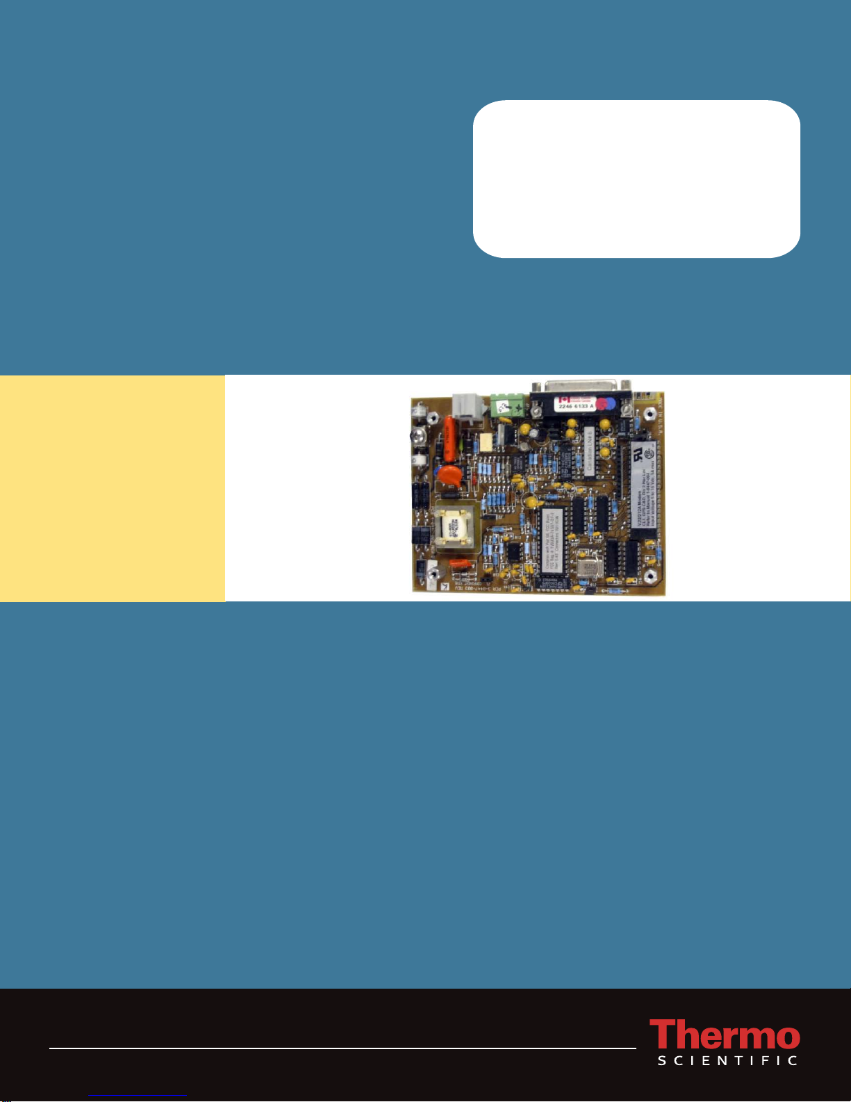
1.2 V.22/212A MODEM DESCRIPTION
The V.22/212A Modem Card is FCC certified and is an UL and CSA Recognized Component for
use in Class I, Division 2, Groups C and D hazardous locations. It is verified to comply with the
limits for a Class A computing device (industrial application) with Part 15 of the FCC rules and is
certified to comply with Part 68 telecommunications rules of the FCC. It is also certified to meet the
CS-03, Issue 7, of Industry Canada. When wired according to the installation section of this manual,
using Class-I, Division-2 wiring methods outlined in the National Electrical Code (NEC) NFPA-70
or in Section 18 of the Canadian Electrical Code, Part 1, the modem may safely be operated in a
Class I, Division 2, Groups C or D hazardous location.
The full-duplex, two-wire, 300-2400 baud, dial-up modem is compatible with CCITT
V.22bis/V.22/V.21, and Bell 212A/103 data communications standards. It automatically performs a
complete handshake as defined by V.22bis/V.22/V.21, and Bell 212A/103 standards, determining
the baud rate and operating mode when connected to a remote modem. The modem also supports
the AT Commands compatible with the Hayes SmartmodemTM command set. Non-Volatile
EEPROM is provided to store user configuration.
Designed for remote telemetry systems, the modem operates on a 5 to 15 Vdc input power and draws
a very low 60 mA (typical). The modem also includes a switched-power mode, providing a typical
standby current of 50 µA. The V.22/212A modem has an operating-temperature range of -40EF to
+185EF (-40EC to +85EC) and a humidity range of 0% to 95% non-condensing.