Thermo Scientific ALPHA COND 550 - REV 5 User manual

Alpha COND550
Conductivity Monitor
mS/µS/ºC/ºF meter


Preface
This manual serves to explain the use of the Alpha-COND 550 Industrial
Conductivity Monitor. The manual functions in two ways, firstly as a step by step
guide to help the user operate the instrument. Secondly, it serves as a handy
reference guide. This instruction manual is written to cover many anticipated
applications of the Alpha-CON 550 monitor. If you have doubts in the use of the
instrument, please do not hesitate to contact the nearest Alpha Authorised
Distributor.
The information presented in this manual is subject to change without notice as
improvements are made, and does not represent a commitment on part of Thermo
Scientific.
Thermo Scientific cannot accept any responsibility for damage or malfunction of the
unit due to improper use of the instrument.
Copyright ©2006
All rights reserved.


TABLE OF CONTENTS
1. Introduction ...........................................................................................................1
1.1 Before You Begin................................................................................................................... 1
1.2 Intended Use.......................................................................................................................... 1
1.3 Safety Instructions.................................................................................................................. 2
1.4 Taking Out of Service / Correct Disposal of the Unit ............................................................. 2
2. Getting Started ......................................................................................................3
2.1 Description of Instrument ....................................................................................................... 3
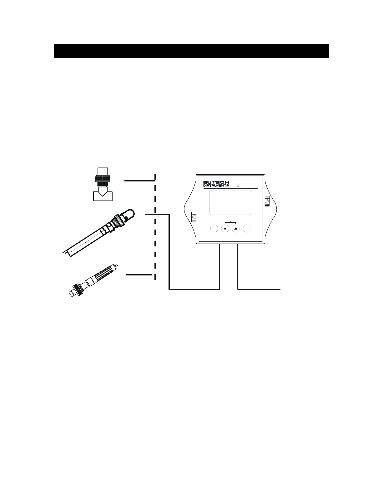
2.2 Measurement System ............................................................................................................ 4
2.3 Connecting Peripherals.......................................................................................................... 5
2.3.1 Connection Terminals.................................................................................................... 5
2.3.2 Switching Between Pt100 & Pt1000 Temperature Sensors.......................................... 6
2.3.3 Connecting Conductivity Probe..................................................................................... 7
2.3.4 Connecting Temperature Probe.................................................................................... 7
2.4 Installation.............................................................................................................................. 8
2.4.1 Mechanical Dimensions................................................................................................. 8
2.4.2 Wall Mount..................................................................................................................... 8
2.4.3 Panel Mount................................................................................................................... 9
2.5 Display & Keypad................................................................................................................. 10
2.5.1 Display Overview......................................................................................................... 10
2.5.2 Key Functions.............................................................................................................. 11
3. Operation .............................................................................................................12
3.1 Measurement mode ............................................................................................................. 12
3.2 Menu Overview .................................................................................................................... 13
4. Calibration Mode .................................................................................................14
4.1 About Calibration.................................................................................................................. 14
4.2 Calibration............................................................................................................................ 15
5. Setup Mode..........................................................................................................17
5.1 Enter Setup mode ................................................................................................................17
5.2 Temperature Coefficient Settings......................................................................................... 18
5.3 Temperature Settings........................................................................................................... 19
5.4 Measuring Range Settings................................................................................................... 21
5.5 Configuration Settings..........................................................................................................22
5.6 Viewing Electrode Properties............................................................................................... 24
6. Technical Specifications.....................................................................................25
7. List of Accessories .............................................................................................27
8. Troubleshooting..................................................................................................28
9. General Information ............................................................................................29
9.1 Warranty............................................................................................................................... 29
9.2 Return of Goods................................................................................................................... 29
9.3 Guidelines for Returning Unit for Repair.............................................................................. 29
10. Appendices.......................................................................................................30
10.1 Appendix 2 Conductivity of various aqueous solutions....................................................... 30
10.2 Appendix 4 - Abbreviations Used in LCD............................................................................. 31


Instruction Manual Alpha-COND550
1
1.Introduction
1.1 Before You Begin
We thank you for purchasing the Alpha COND550 monitor.
The construction of the COND550 monitor employs leading edge technology
and complies with safety regulations currently in force. Notwithstanding this,
improper use could lead to hazards for the user or a third-party, and/or
adverse effects on the plant or other equipment. Therefore, the operating
instructions must be read and understood by the persons involved before
working with the monitor.
The instruction manual must always be stored close at hand, in a place
accessible to all people working with the conductivity monitor.
If you have questions, which are not or insufficiently answered in this
instruction manual, please contact your authorized supplier. They will be glad
to assist you.
1.2 Intended Use
Alpha COND550 monitors are intended solely for conductivity and
temperature measurement, as described in this instruction manual.
Any other use, or use not mentioned here, that is incompatible with the
technical specifications is deemed inappropriate. The operator is solely
responsible for any damage arising from such use.
Other prerequisites for appropriate use include:
–Comply with the instructions, notes and requirements set out in this
instruction manual.
–Comply with all local safety regulations concerning safety at work.
–Comply with all information and warnings in the documentation dealing
with the products used together with the conductivity monitor (housings,
sensors, etc.).
–Comply with local environmental and operational conditions.

Instruction Manual Alpha-COND550
2
1.3 Safety Instructions
- The Alpha COND550 monitor should be installed and operated only
by personnel familiar with the instrument and who are qualified for
such work.
- A defective CON monitor must neither be installed nor put into
service.
- The Alpha COND550 must only be operated under the specified
operating conditions (see section 6).
- The Alpha COND550 must not be repaired by the customer.
- No modifications to the Alpha COND550 are allowed. The
manufacturer/supplier accepts no responsibility for damage
caused by unauthorized modifications. The risk is borne entirely
by the user.
1.4 Taking Out of Service / Correct Disposal of the Unit
Taking out of Service
•First disconnect the unit from the power supply and then undo all electrical
connections.
•Remove the unit from the wall / panel.
Correct Disposal of the Instrument
When the Alpha COND550 monitor is permanently taken out of service, obey
the local environmental regulations for correct disposal or send the
instrument to your local distributor, they will take care of proper disposal.

Instruction Manual Alpha-COND550
3
2.Getting Started
2.1 Description of Instrument
The Alpha COND550 monitor is used for measuring conductivity and
temperature values. The monitor can be used for applications such as water
treatment and controlling, galvanic-decontamination, chemical processing,
food processing, clean or wastewater control and neutralization processes.
The monitor has many user-friendly and safety features which include:
•Push-button keypad for calibration and setup
•Built-in non-volatile memory to ensure that calibration and other
information are not erased if power supply fails
•Menu-driven program that simplifies setup
•Automatic temperature compensation (ATC)
•Manual temperature compensation setting without the ATC probe, with
independent setting for calibration and process temperature
•Large dual display LCD for easy reading with clear multiple annunciators,
operational mode indicators and error indicators

Instruction Manual Alpha-COND550
4
2.2 Measurement System
A typical measurement system consists of:
•A conductivity process monitor
•A conductivity sensor with integrated or separate Pt100/Pt1000
temperature sensor
•An appropriate measurement cable
•An immersion, flow or process assembly
PowerAdaptor
(+9 V DC)
Measurement Cable
Housing and
Sensors
Alpha COND550 Monitor
ENT
ESC
pH Monitor
lpha pH560
CAL

Instruction Manual Alpha-COND550
5
2.3 Connecting Peripherals
2.3.1 Connection Terminals
Remove Back Cover:
Remove the screws from the four corners at the back of the conductivity
monitor. Remove the back cover. The connectors are exposed on the back
PCBA as shown in the Figure 1 below.
Connectors:
•J11 – 24V DC power connector
•J8 – 9V DC power connector (1.2mm diameter)
•J9 – Relay connections
•J10 - Conductivity electrode & Temperature probe connections (wiring has
to be done in the detachable connector
J10
J8
9V DC Power
Screw
Figure 1: Outer Side of Back PCBA
J10 Connections
1. CON Low Current
2. CON Low Voltage
3. CON High Voltage
4. CON High Current
5. Pt 100 Compensate
6. Pt 100 Sense
7. Pt 100 GND
8. (No connection)
24V DC
J11
J11 Connections
1. +ve
2. Gnd 1)+ve
2)Gnd

Instruction Manual Alpha-COND550
6
2.3.2 Switching Between Pt100 & Pt1000 Temperature Sensors
The conductivity monitor supports both Pt100 & Pt1000 (2-wire or 3-wire)
temperature sensors. The default factory setting is Pt100. If you need to use
Pt1000 temperature sensor, you have to change the jumper setting (J7) as
described below.
Remove Back Cover:
Remove screws from the four corners at the back of the conductivity monitor.
Remove the back cover.
Remove Back PCBA:
Remove the screw located center of the back PCBA
(Figure 1). Detach the back PCBA from the monitor. Turn over the back PCBA.
Locate J7 jumper on the inner side of the back PCBA as shown in Figure 2
below.
Figure 2: Inner Side of Back PCBA
Set Jumper J7:
Set the J7 jumper to required sensor (Pt100 or Pt1000) type.

Instruction Manual Alpha-COND550
7
2.3.3 Connecting Conductivity Probe
Any industrial conductivity probe (2-cell or 4-cell) can be connected to the
conductivity monitor.
2-Cell Conductivity Probe:
1. Short Pin 1 & 2 of J10 connector using a jumper wire.
2. Connect CON low input wire (white) to Pin 2 of J10 connector.
3. Connect CON high input wire (black) to Pin 3 of J10 connector.
4. Short Pin 3 & 4 of J10 connector using a jumper wire.
4-Cell Conductivity Probe:
1. Connect CON low input wire (black) to Pin 1 of J10 connector
2. Connect CON low input wire (white) to Pin 2 of J10 connector.
3. Connect CON high input wire (orange) to Pin 3 of J10 connector.
4. Connect CON high input wire (blue) to Pin 4 of J10 connector.
2.3.4 Connecting Temperature Probe
For Automatic Temperature Compensated (ATC) conductivity readings, an
in-built temperature sensor is usually integrated with industrial conductivity
probes. Alternatively, a separate 100ΩPt RTD temperature probe (2-wire or
3-wire) can be connected to the monitor.
3-Wire Probe:
1. Connect PT100 compensate wire to Pin 5 of J10 connector.
2. Connect PT100 sense wire to Pin 6 of J10 connector.
3. Connect PT100 GND wire to Pin 7 of J10 connector.
2-Wire Probe:
1. Short Pin 5 & 6 of J10 connector using a jumper wire.
2. Connect PT100 sense wire to Pin 6 of J10 connector
3. Connect PT100 GND wire to Pin 7 of J10 connector.

Instruction Manual Alpha-COND550
8
2.4 Installation
2.4.1 Mechanical Dimensions
ENT
ESC
Conductivity Monitor
lpha COND550
CAL
2.4.2 Wall Mount
11
Pierce through holes at
both sides
2
Cover the catch slots at
both sides with overlays

Instruction Manual Alpha-COND550
9
2.4.3 Panel Mount
Panel
Gasket
Prepare panel cut-out of
92.0 mm X 92.0 mm
Remove back cover of
conductivity monitor
and slide it through
panel cut-out
Attach catch to both sides
of conductivity monitor
Insert threaded rods through catch
until conductivity monitor is held
against panel
2
3
4
1
1
Panel

Instruction Manual Alpha-COND550
10
2.5 Display & Keypad
2.5.1 Display Overview
The Liquid Crystal Display (LCD) of Alpha COND550 conductivity monitor has
two alpha-numerical displays (Upper and a Lower).
•Upper display: Measured conductivity value is displayed when the
monitor is in normal operation (measurement) mode.
•Lower display: Measured temperature value is displayed when the
monitor is in normal operation (measurement) mode. In conductivity
calibration mode, measured conductivity values are displayed here.
The two displays indicate function names, options & settings in Setup mode.
Refer ‘Appendix 4 - Abbreviations Used in LCD’ for more details.
The LCD also consists of various mode indicators, status annunciators and
unit of measurement indicators.
mS
R.
SETUP MEAS CAL
Upper Display
Lower Display
ERR
ATC
°C
READY
8.8.8.8
.8.8.8
-
-
HOLD
°F
µS
%
K=
Mode Indicators
MEAS Measurement mode (Refer Section 3.1 )
SETUP Setup mode (Refer Section 5)
CAL Calibration mode (Refer Section 4)
Status Annunciators
READY Appears when the reading is stable
HOLD Appears in Setup mode and Calibration mode to indicate that the relay function
is frozen
ATC Appears when Automatic Temperature Compensation (ATC) is enabled.
Not visible when Manual Temperature Compensation (MTC) is enabled.
Flashes if the temperature probe is faulty in its ATC mode. (Refer Section 5.3)
ERR Appears when an error occurs
Electrode annunciator. Blinks during calibration error (Refer Section 4.2)
Buffer annunciator. Appears in calibration mode (Refer Section 4.2)
K Cell Constant (Refer Section 4.2)

Instruction Manual Alpha-COND550
11
2.5.2 Key Functions
ENT
ESC
Conductivity Monitor
lpha COND550
CAL
Key Description
CAL
Enter Calibration mode
ENT
Enter Setup mode
Access sub screens (parameters) within a group of settings in Setup
mode
Confirm (save) setup parameters and numerical values
Start/Confirm calibration in Calibration mode.
Select a group of settings in Setup mode.
Select parameters and increment/decrement numerical values in Setup
and Calibration modes.
(When pressed continuously, speed of value increment/decrement
increases)
Returns to Measurement mode when both keys are pressed
simultaneously.
Units of Measurement Indicators
mS Conductivity in Milli Siemens
µS Conductivity in Micro Siemens
R. Line Resistance in Ohms (Refer Section 5.5)
% Temperature Coefficient (Refer Section 5.2)
ºC Temperature in Celsius (Refer Section 5.3)
ºF Temperature in Fahrenheit (Refer Section 5.3)

Instruction Manual Alpha-COND550
12
3. Operation
3.1 Measurement mode
When the conductivity monitor is powered on, the display shows all the LCD
segments briefly, and then automatically enters into the measurement mode.
µS
MEAS
ATC
°C
READY
25.0
The mode indicator ‘MEAS’ at the top of the display indicates that the
conductivity monitor is in measurement mode. The upper alpha-numerical
display shows the measured conductivity value, while the lower display
shows the temperature value.
The monitor has five selectable measuring ranges. The unit of measurement
and resolution of the conductivity reading depend on the selected measuring
range. If the monitor reads a conductivity reading beyond the selected
measuring range, the display shows ‘Or’ (over range) error indicator.
NOTE: To guarantee accurate readings, the measuring system (the
conductivity monitor and the sensor) must be calibrated regularly.
From measurement mode you can access:
•Calibration mode (by pressing CAL key)
•Setup mode (by pressing ENT key)
For more details, refer section 4 for Calibration mode and section 5 for Setup
mode.)

Instruction Manual Alpha-COND550
13
3.2 Menu Overview
MEAS
µS
°C
ATC
READY
ENT
SETUP
HOLD
SETUP
HOLD
ENT
SETUP
HOLD
SETUP
HOLD
SETUP
HOLD
ENT
ENT
ENT
ENT
CAL ENT
ENT
ENT
ENT
ENT
ENT

Instruction Manual Alpha-COND550
14
4.Calibration Mode
4.1 About Calibration
Calibration should be carried out each time a new electrode is attached to the
monitor or when you suspect that the monitor/electrode is out of calibration.
The monitor allows you to perform temperature calibration and conductivity
calibration.
About Temperature Calibration
It is important to ensure that temperature calibration is carried out prior to
conductivity calibration since temperature readings affect the accuracy of
conductivity measurements. It is recommended that temperature calibration
should be carried out only if the temperature value displayed on the monitor
is different from that of a calibrated thermometer. A temperature offset
calibration of ± 10 °C/± 18 °F from the default reading is allowed. Once a
temperature calibration is performed, conductivity calibration should be
carried out to ensure the accuracy of conductivity measurements.
About Measuring Ranges & Conductivity Calibration
The monitor has five selectable conductivity measuring ranges. You can only
calibrate one-point in the measuring range that you have selected for your
process application. You have to recalibrate the monitor every time you
change the measuring range since the calibration data of the monitor will be
reset every time a new measuring range is selected.
About Conductivity Calibration
During conductivity calibration, the monitor allows a calibration window of
± 40% from the measured default reading of the calibration standard. The
minimum allowable calibration point is 10% of the full scale reading of the
measuring range selected.
For best results, select a standard conductivity solution close to the sample
value you are measuring.
This manual suits for next models
1
Table of contents
Other Thermo Scientific Monitor manuals

Thermo Scientific
Thermo Scientific INNOVA Series User manual

Thermo Scientific
Thermo Scientific 5028i User manual

Thermo Scientific
Thermo Scientific Vanquish Charger User manual

Thermo Scientific
Thermo Scientific ALPHA COND 550 User manual

Thermo Scientific
Thermo Scientific Alpha pH 550 User manual

Thermo Scientific
Thermo Scientific Orion 2111LL User manual

Thermo Scientific
Thermo Scientific 3600 PDM User manual

Thermo Scientific
Thermo Scientific personalDATARAM pDR-1000AN User manual

Thermo Scientific
Thermo Scientific SAM12 User manual

Thermo Scientific
Thermo Scientific Alpha pH 550 User manual