Thermocable ProReact EN Analogue User manual
World leading linear detection
www.thermocable.com
Linear Detection Technology Made Simple
Page 1 of 8 Revision 1.0 Mar 2020
ProReact EN Analogue Cable Test Kit Instructions
Document Ref. PACC-CTK
ProReact EN Analogue
Linear Heat Detection
Sensor Cable Testing Instructions

Page 2 of 8 Revision 1.0 Mar 2020
ProReact EN Analogue Cable Test Kit Instructions
Document Ref. PACC-CTK
Contents:
ProReact EN Analogue Sensor Cable Test Kit Page 3
- Overview
- Kit Contents
- Technical Information
Operating Instructions Page 6
Troubleshooting Page 8

Page 3 of 8 Revision 1.0 Mar 2020
ProReact EN Analogue Cable Test Kit Instructions
Document Ref. PACC-CTK
ProReact EN Analogue Sensor Cable Test Kit
Overview
The ProReact EN Analogue Sensor Cable Test Kit provides users with a
practical and safe method of verifying the operational performance of
Thermocable’s ProReact EN Analogue Sensor Cable post-installation.
Testing is recommended to be undertaken periodically to ensure correct
operation of the system. The functional test must be carried out on 1-3%
of the total sensor cable length, which should have been made accessible
during the system design and installation as per the manufacturer’s
recommendations.
A functional test is straightforward to be undertaken and a test kit can be
re-used where necessary.
Kit Contents
Each ProReact EN Analogue Sensor Cable Test Kit (A1900) contains:
Part Code Product Description Quantity Spare part availability
A1904 120V/240Vac to 50Vac Power supply unit 1 3
A1901 ProMinder Red Cable for zone lengths between 50m to 125m 1 3
A1902 ProMinder Blue Cable for zone lengths between 100 to 350m 1 3
A1903 ProMinder Brown Cable for zone lengths between 175m to 500m 1 3
A1905 35x450mm length (10mm internal diameter) pipe insulation 1 3
A1175-100 110°C constant rated indoor/outdoor tie wrap (Pack of 100) 1 3
Page 4 of 8 Revision 1.0 Mar 2020
ProReact EN Analogue Cable Test Kit Instructions
Document Ref. PACC-CTK
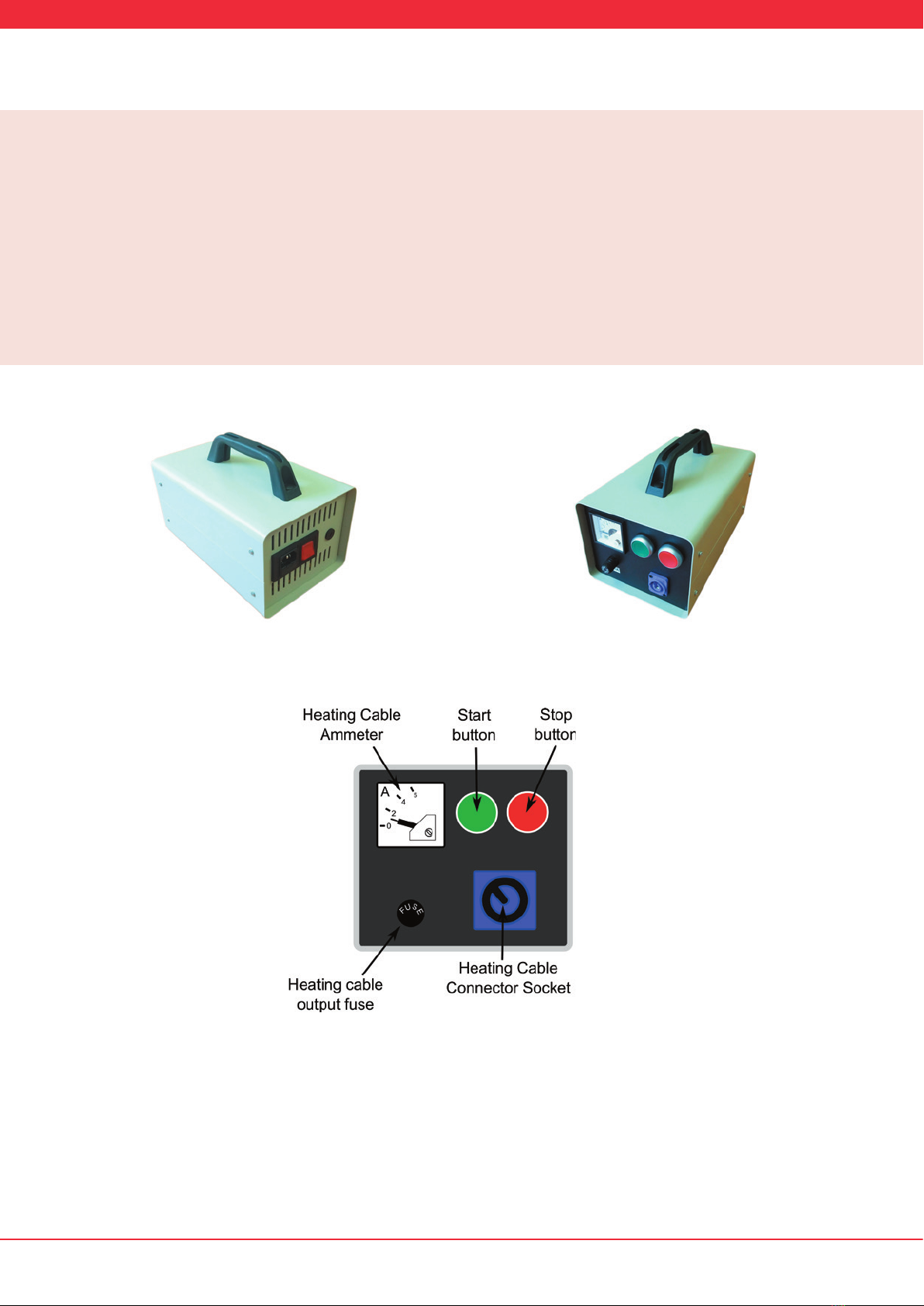
Figure 3: Power supply unit front panel
Figure 2: Power supply unit front
Technical Information: 120V/240Vac to 50Vdc Power supply unit
Part No: A1904
Part Description: 120V/240Vac to 50Vac power supply unit
Dimensions (inc. handle): 185mm H x 160mm W x 260mm D
Operating Temperature: 0⁰C to +50⁰C
Operating Humidity: 0% to 90% RH
Input Voltage: 120V or 240Vac switchable
Output Voltage: 50Vac
Max. Input Current: 1.5A
Max. Output Current: 5A
Figure 1: Power supply unit rear

Page 5 of 8 Revision 1.0 Mar 2020
ProReact EN Analogue Cable Test Kit Instructions
Document Ref. PACC-CTK
Technical Information: ProMinder Cable(s)
Diameter: 6.35mm (0.250 in)
Minimum Bend Radius: 50mm
Operating Temperature: -40⁰C to +40⁰C
Operating Humidity: 0 to 99% RH
Thermal Power Output: Approx. 15W/m
Part code Part Description Heated Length (m)
A1901 ProMinder Red Cable for zone lengths between 50m - 125m 3.6
A1902 ProMinder Blue Cable for zone lengths between 100 - 350m 10.2
A1903 ProMinder Brown Cable for zone lengths between 175m - 500m 16.6
(each cable includes 5m cold lead with plug on for connecting to power supply unit)
Page 6 of 8 Revision 1.0 Mar 2020
ProReact EN Analogue Cable Test Kit Instructions
Document Ref. PACC-CTK
Operating Instructions
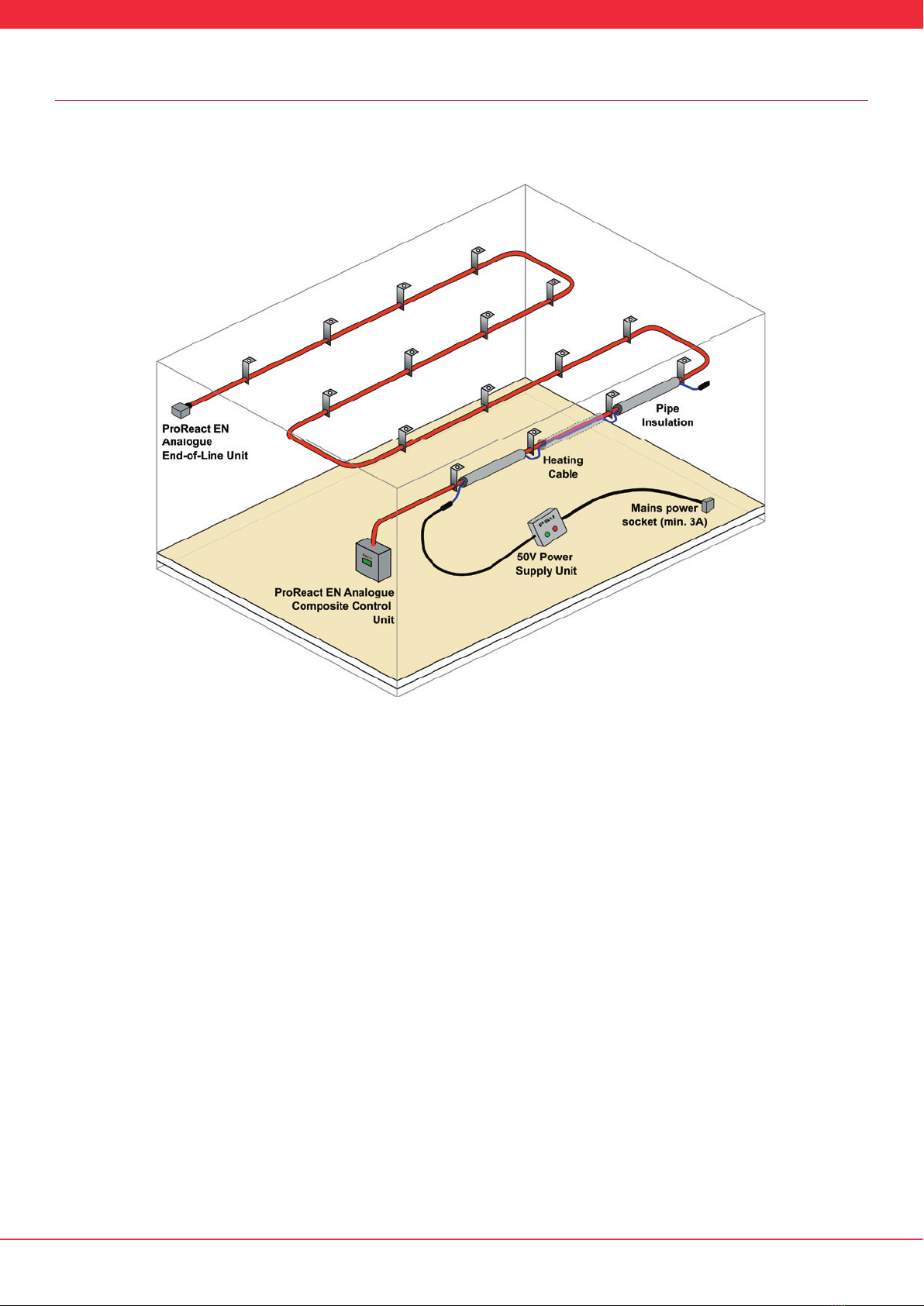
The ProReact EN Analogue Sensor Cable Test Kit can be used to carry out a functional test on a ProReact EN Analogue LHD system. The
test kit is designed to heat up between 1% and 3% of the sensor cable, simulating a real re or overheat condition. A typical test setup
is shown in Figure 4.
1. Determine the zone length of the sensor cable that is to be tested. If the zone length is not known, it can be calculated by dividing
the calibration resistance in kohms (which should be recorded on the label on the reverse of the controller lid) by 0.017.
For example, if the calibration resistance is 1.50kohms then the zone length is approximately 1.5 / 0.017 = 88m.
2. Based upon the zone length, select the most suitable heating cable:
1. Zone length between 50m to 125m →select ProMinder Red cable
2. Zone length between 100m to 350m →select ProMinder Blue cable
3. Zone length between 175m to 500m →select ProMinder Brown cable
3. Locate a suitable section of sensor cable to attach the heating cable to. A minimum of 1% of the sensor cable will need to be
heated but for the best test results, try and attach the heating cable to approximately 3% of the sensor cable. For example, if the
zone length is 88m as previously calculated, attach the ProMinder Red cable to 2.6m (3% of 88 metres) section of sensor cable. It is
acceptable to attach the heating cable to more than 3% of the sensor cable if possible.
4. The heating cable should be in close proximity to the sensor cable for the heat to transfer eectively. It is acceptable for the sensor
cable and heating cable to touch each other. To further aid in the heat transfer x pipe insulation around the heating cable and
sensor cable to prevent excessive heat loss during the test. Not enough heat is generated by the heating cable to raise the
temperature of the sensor cable sufficiently in order to trigger an alarm without the use of the pipe insulation.
5. The pipe insulation is provided in 450mm lengths so it can be xed between support brackets installed at the recommended
spacing.
Figure 4: Typical ProReact EN Analogue Sensor Cable Test Kit setup

Page 7 of 8 Revision 1.0 Mar 2020
ProReact EN Analogue Cable Test Kit Instructions
Document Ref. PACC-CTK
Operating Instructions contd.
6. It may be preferable to temporarily secure the heating cable to the sensor cable using the provided tie wraps. Alternatively, it is
acceptable to temporarily attach the heating cable to the support brackets.
7. Once the heating cable has been xed in place and the pipe insulation placed around the sensor cable and heating cable, plug the
heating cable into the power supply unit on the front panel (see Figure 3). The heating cable plug pushes into the socket and then
twists clockwise to lock in place. To remove the heating cable pull the silver lever back on the plug and twist anti-clockwise.
8. Before plugging the power supply unit into a suitable mains outlet, check the supply voltage switch on the rear panel of the
power supply unit is set to the appropriate voltage (either 240Vac or 120Vac). The supply voltage switch is set to 240Vac by
default. Use a at screwdriver to turn the supply voltage switch to the correct setting. The power supply unit may be damaged if
the supply voltage switch is set incorrectly.
9. Plug the power supply unit into a mains supply, able to supply a minimum of 3A, using the supplied lead. If a dierent mains outlet
plug is required it may be sourced locally and connected into the power supply unit 3-pin C14 IEC socket on the rear panel.
10. Once the power supply unit has been plugged in it should power up and the red Stop button will be lit.
11. Ensure the heating cable is installed correctly. Any section of heating cable not installed around the sensor cable should be left in
open air and must not be covered up or overlap with other sections of the heating cable, which may result in overheating.
12. Where possible, it will aid testing of the ProReact EN Analogue system to reduce the chosen alarm temperature to the lowest
setting for the purpose of the test. For example, if the current alarm temperature setting is 100 deg C, for the duration of the
test the alarm temperature setting should be changed to 64 deg C or 54 deg C. The minimum alarm temperature setting will
depend upon the present ambient temperature of the sensor cable, a higher ambient temperature will necessitate a higher alarm
temperature. Refer to the ProReact EN Analogue installation and instruction manual for guidance. If the alarm temperature setting
was changed always return the setting to the original value once the test is completed.
13. Press the green Start button on the front panel of the power supply unit to start the test. The green Start button will light up
and the red Stop button light will turn o. The power supply unit supplies power to the heating cable for approximately 20
minutes, during which time the temperature around the sensor cable where the heating cable has been installed should increase
suciently enough to trigger an alarm.
14. After the green Start button has been pressed, check the ammeter on the power supply unit front panel to ensure the heating
cable is receiving power.
1. For the ProMinder Red cable the ammeter should show approximately 1A
2. For the ProMinder Blue cable the ammeter should show approximately 3A
3. For the ProMinder Brown cable the ammeter should show approximately 4.9A
If the ammeter does not show the correct value, press the red Stop button immediately and investigate why the current may
be incorrect (see troubleshooting section).
15. No further action needs to be taken with the power supply unit during the test. It may be helpful to monitor the current sensor
cable resistance on the analogue control unit under test to check the resistance is decreasing as the test progresses (see the
ProReact EN Analogue installation and instruction manual for reading the current sensor cable resistance).
16. An alarm should be triggered on the ProReact control unit before the 20 minute test period is over. The heating cable heats up
slowly to prevent overheating and requires a minimum of 5 minutes to reach a temperature required to trigger an alarm. It may be
necessary in some installations and test setup to wait for the entire test period before an alarm is triggered. Monitor the control
unit resistance to determine if and when an alarm is going to be triggered.
17. After 20 minutes the power supply unit will automatically switch o the heating cable, the red Stop button light will turn on and
the green Start button light will turn o. The heating cable can take up-to 20 minutes to cool down before a test can be repeated. It
is strongly advised not to immediately restart a test as this may result in the sensor cable or heating cable being damaged.
18. After a successful test the heating cable and pipe insulation should be carefully removed from the sensor cable section and the
sensor cable checked for any signs of damage or overheating.

Page 8 of 8 Revision 1.0 Mar 2020
ProReact EN Analogue Cable Test Kit Instructions
Document Ref. PACC-CTK
www.thermocable.com
Call: +44 1274 882359
•
M
A
D
E
I
N
T
H
E
U
K
•
M
A
D
E
I
N
T
H
E
U
K
Email: info@thermocable.com
Thermocable (Flexible Elements) Ltd,
Pasture Lane, Bradford, BD14 6LU
United Kingdom
Troubleshooting
If the ammeter does not move after the green button is pressed, check the cable is attached correctly to the power supply unit.
Disconnect power to the power supply unit and check the fuse on the front panel (see Figure 3). The fuse can be removed by twisting
the fuse plug anti-clockwise.
If the power supply unit red Stop button does not light up after connecting the unit to a mains supply. Check the fuse on the mains
lead is working and check the fuses on the rear of the power supply unit located directly below the mains lead socket.
Other manuals for ProReact EN Analogue
1
Table of contents
Popular Accessories manuals by other brands

PCB Piezotronics
PCB Piezotronics 401B04 Installation and operating manual

Bosch
Bosch SCD 110 quick start guide

LaZee Tek
LaZee Tek eeZee Mouse CURSOR quick start

elsner elektronik
elsner elektronik KNX W sl Installation and adjustment

Owon
Owon WSP408 quick start guide

Edirol
Edirol EDIROL FA-101 install guide


