Thermofilm Heatstrip THY2200P User manual

Product & Assembly
Manual
H EATS TR IP ® I n t e n s e Portable Elec tr ic
Heat er
Model THY2200P
For HEATSTRIP Installation video go to: www.youtube.com, search HEATSTRIP www.heatstrip.com.au
2
For repairs or replacement parts, please contact:
Thermofilm Australia Pty Ltd
17 Johnston Court, Dandenong South, Victoria 3175, Australia
Telephone: (03) 9562 3455
8:30am-5:00pm Mon-Fri (EST)
Email: sales@thermofilm.com.au
To obtain the correct replacement parts for your electric radiant heater, please refer to
the part numbers in this parts list. The following information is required to ensure you
receive the correct parts:
1. Model and Serial Number (see label on the heater)
2. Part Number
3. Part Description
4. Quantity of parts needed
Important: Use only Thermofilm replacement parts. The use of any part that is not a
Thermofilm replacement part can be dangerous and void your product warranty. Keep
this Instruction Manual for convenient referral and for parts replacement.
Contents
Product Overview 3
Specifications 3
Product Features & Benefits 3
Installation Requirements 4
Parts List 4
Product Parts Diagram 5
Hardware Pack & Tools Required 6
Assembly Instructions 7
Electric Heater Assembly Instructions 7-9
Maintenance and Safety 10
Replacement Parts 10
Warranty 11
Manual # Rev B - Date:20/12/2017

3
Specifications - Australia
MODEL POWER
(WATTS)
CURRENT
(AMPS)
DIMENSIONS (mm) WEIGHT
(Kg)
LEAD
LENGTH
(mm)
PLUG
THY2200P 2200 9.2 1068(W) x 2050(H) x 500(D) 20 3000 Yes
HEATER TYPE High intensity electric radiant heater with carbon filament element.
POWER 230-240 Volts Nominal at 50—60 Hertz, Single Phase
CONNECTION 3 Core Cable 2.5mm2
APPROVALS AUSTRALIA/NZ
PROTECTION RATING IPX5 Protection from water ingress from all directions
MATERIAL OF CONTRUCTION Heater: Black anodized alloy casing & endcaps, powder coated grille
Stand: Powder coated mild steel
Features & Benefits
Stylish, high quality portable, free-standing outdoor heat-
er stand
Ideal for alfresco areas, balconies, apartments & hospi-
tality (internal & external use)
High Temperature Output
All black construction with attractive hexagonal shaped
grille
Instantaneous Heat
Infrared Carbon Filament Element
Concealed power cable ensures a sleek appearance
Components are sub-assembled for easy DIY installation
In-built wheels for easy portability, perfect for residential
and commercial applications
Corrosion protected for even the toughest environments
2 year residential and 1 year commercial warranty
Tips
If an extension lead is required, use one as short as pos-
sible, as a long lead may result in performance loss
Locate the heater as close to the power point as possible
This portable heater is for spot heating only. Locate as
close to the area you want to heat as possible (e.g Ta-
ble)
Store under cover at all times
MODEL INDOOR PROTECTED (m2 ) OUTDOOR ENCLOSED (m2 ) OUTDOOR EXPOSED (m2 )
THY2200P 14 95
Heating Area
4
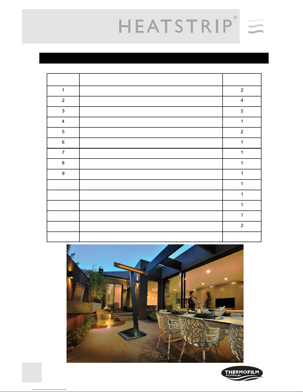
Parts List of THY2200P
Key Description QTY
Wheel
Skid Pad
Base
Kick Plate
Fixed Bracket
Post - Rear, Lower
Post - Rear, Upper
Post - Front, Lower
Post - Front, Upper
10 Side Panel / Left
11 Side Panel / Right
12 Rear Panel
13 Heater Bracket
14 Base Bracket
15 Electric Heater, 2200W 1
5
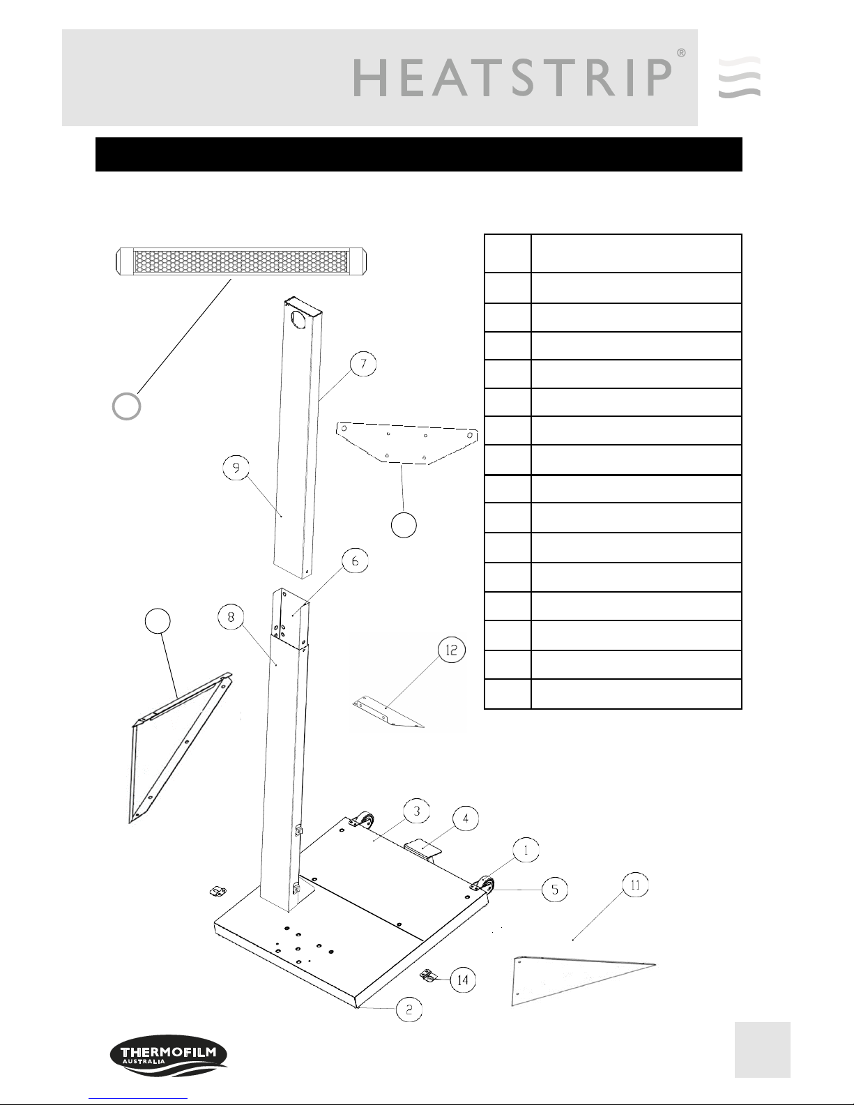
Parts Diagram
Key Description
1Wheel
2Skid Pad
3Base
4Kick Plate
5Fixed Bracket
6Post—Rear, Lower
7Post—Rear, Upper
8Post—Front, Lower
9Post—Front, Upper
10 Side Panel / Left
11 Side Panel / Right
12 Rear Panel
13 Heater Bracket
14 Base Bracket
15 Electric Heater Model THY2200
15
13
10
6
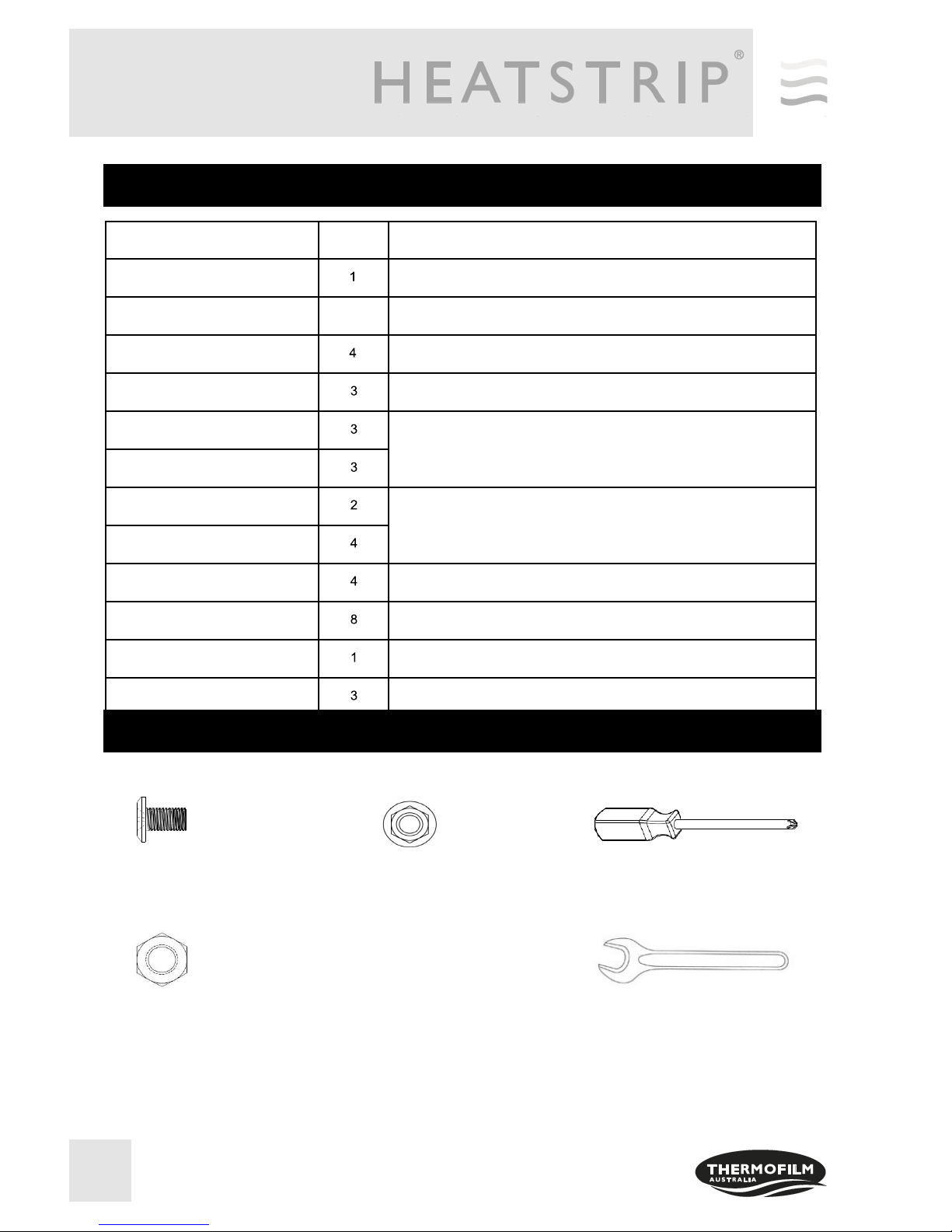
Pan Head Screw M6x10mm
QTY: 39
Hardware Diagram for THY2200P
PART DESCRIPTION QTY PURPOSE OF PART
Hardware Pack For use in assembly of THY2200P
Pan Head Screw M6 x 10mm 5Connecting Base
Pan Head Screw M6 x 10mm Install Base Brackets to Base
Pan Head Screw M6 x 10mm Install Lower Post to Base
Pan Head Screw M6 x 10mm
Install Side Panels to Lower Post & Base
Pan Head Screw M6 x 10mm
Pan Head Screw M6 x 10mm
Install Real panel to Side Panel & Lower Post
Pan Head Screw M6 x 10mm
Pan Head Screw M6 x 10mm Install Heater Bracket to Upper Post
Pan Head Screw M6 x 10mm Install Upper Post to Lower Post
Screwdriver
Pan Head Screw M6 x 10mm Install Lower Post to Base
Hardware Pack For THY2200P
Phillips Head Screwdriver
Flange Nut M6
QTY: 15
Hexagon Nut M12
QTY: 2
M6 Spanner
7
Assembly Instructions
CAUTION: To assemble this heater, you should obtain assistance from another person when handling the
larger, heavier pieces.
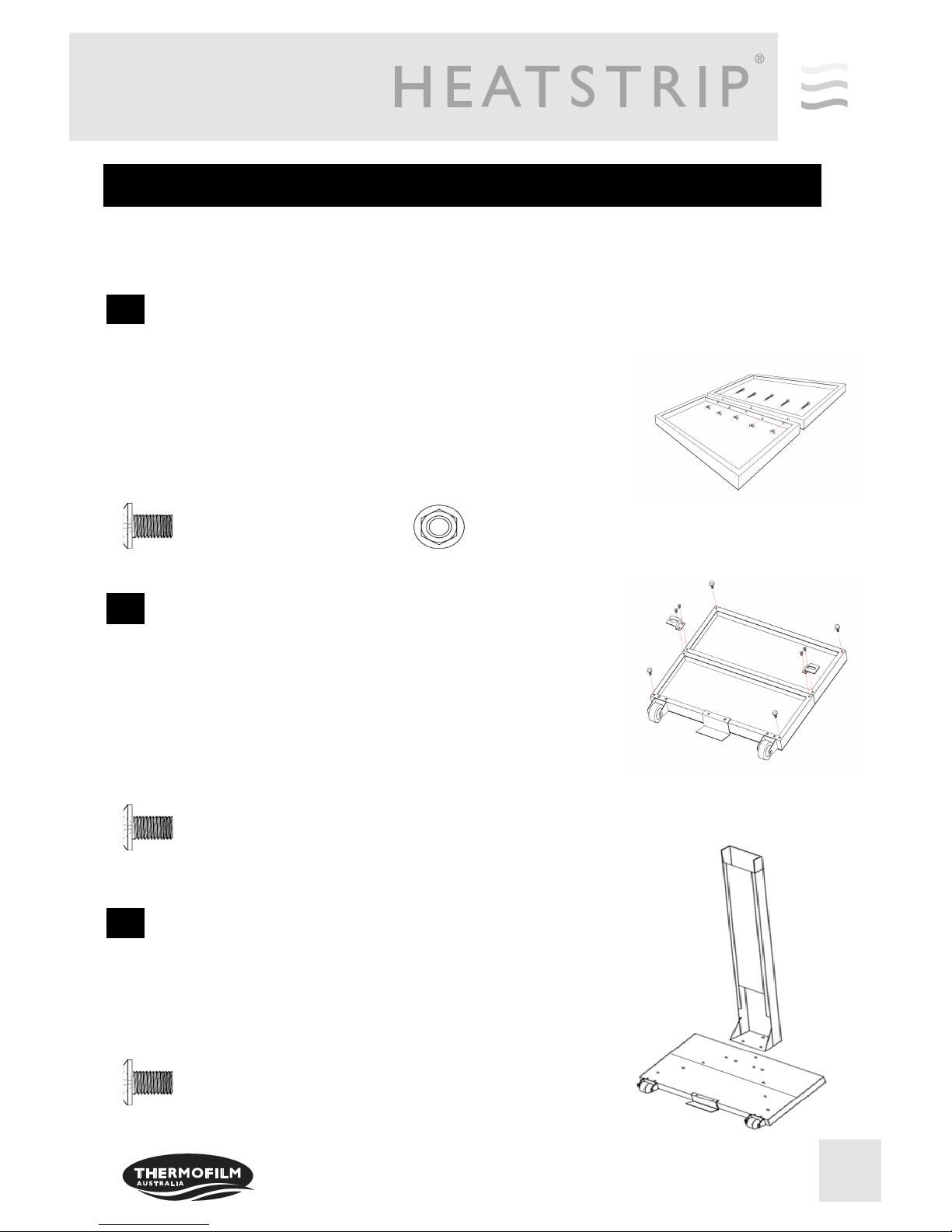
1
Install Base Brackets
Remove all the packing material and place on a non-abrasive
surface.
Position the Base as shown in the diagram.
Once the slotted holes are aligned, use 5 Pan Head screws
then tighten securely with the nuts provided
Install two Brackets to the Base using 4 Pan Head Screws
(M6x10mm), once brackets are in place tighten all the screws
securely.
Adjustable Skid Pads will be provided. Screw Skid Pads on
each corner as shown in the diagram.
Note: Base brackets can be concealed if angled inwards.
Attach the Lower Post to the Base by matching the
slotted holes on the Lower Post into the screws on
the Base. Next, attach 3 Pan Head Screws
M6x10mm, then tighten all the screws securely
Install Lower Post
Joining Base
2
3
Pan Head Screw M6x 10mm
QTY: 4
Pan Head Screw M6x 10mm
QTY: 3
Flange Nut M6
QTY: 5
Pan Head Screw M6x 10mm
QTY: 5

8
Assembly Instructions
CAUTION: To assemble this heater, you should obtain assistance from another person when handling the
larger, heavier pieces.
Place two Side Panels onto the Base.
Install the Left Side Panel to the Lower Post using 2 Pan
Head Screws (M6x10mm). Then place the Left Side Panel to
the Base matching the slotted holes. Once the slotted holes
are matching, use 3 Pan Head Screws (M6x10mm) and
screw securely with the Flange Nuts.
Repeat the same procedure for the Right Side Panel, then
tighten all the screws securely.
Install Side Panels
4
Place and install the Rear Panel to the Lower Post using
2 Pan Head screws. (M6x10mm)
Once the top 2 Pan Head screws are Installed, match the
slotted holes on the Rear Panel to the Side Panels.
Screws all 4 holes securely using 4 pan head screws
(M6x10mm) and Flange Nuts.
Place the bracket head on the top post.
Using the Bracket Head, match the slotted holes to the top post.
Once the slotted holes are matched, use 4 pan head screws
(M6x10mm), then tighten securely shown in the diagram.
Ensure bracket is attached in the correct direction, as per the
diagram.
Install Rear Panel
Install Heater Bracket to the Top Post
5
6
Pan Head Screw M6x10mm
QTY: 6
Pan Head Screw M6x10mm
QTY: 10
Pan Head Screw M6x10mm
QTY: 4
Flange Nut M6
QTY: 6
Flange Nut M6
QTY: 4

9
Assembly Instructions
CAUTION: To assemble this heater, you should obtain assistance from another person when handling the
larger, heavier pieces.
7Install Top Post to the Lower Post
Install the Heater to Bracket Head attached on the Upper Post
Insert and slide the top post over to the lower post connecting
the stand using 8 pan head screws (M6x10mm), then tighten all
screws securely.
Using the 2 brackets, attach the brackets to the heater.
Match the brackets to the slotted holes located on the bracket head shown
in the diagram.
Using 2 Hex nuts bolts, tighten the heater brackets to the bracket head sup-
port securely.
Ensure the heater is centred on the post.
8
Hex Nut M12
QTY: 2
Pan Head Screw M6x10mm
QTY: 8
Tip: Tilt the stand on a chair or a solid non-abrasive surface before
connecting the heater to the bracket head.

10
Assembly Instructions
9Concealing Power Cord
Place the plug into the circular hole located at the top of the upper
post. The plug should drop to the bottom of the heater, pull the cord
gently from the bottom hole. This step will conceal the cord and 3
pin plug.
Remote battery CR2025, 3V, Lithium
Remote range 10m+
Wall socket supply 220V - 240V, 50Hz
Max Load 10A (2400W)
Standby consumption <1W
Remote Frequency 38KHz IR
Dimensions (mm) 105 (H) x 55 (W) x 60 (D)
Approvals Australian Standards AS/NZ
3105, 3112, 3100
Optional Accessory
TT-MTR-PLUG provides an easy means of remotely turning on the appliances that are normally
permanently connected to a standard wall socket.
An easily selected 1 hour, 2 hours and 4 hours timer function accessible on both the wall unit and
remote. Programmable remote control unit capable of controlling multiple units.
TT-MTR-PLUG
Specification

11
Safety
HEATSTRIP® Intense has an IP rating of X5. This means it is protected from water ingress from all directions.
HEATSTRIP® has undergone extensive testing both in laboratory conditions, in Thermofilm’s manufacturing facility in
Melbourne and field trials in Australia and overseas. It is this testing that gives the purchaser the confidence of a high
quality product.
Independent laboratory testing has confirmed Thermofilm’s full compliance with Australian and other International
Standards including CE, AS/ANZ, UL/CSA
HEATSTRIP® is Class 1 equipment and must be earthed.
In operation, this heater is VERY HOT— do not touch any part of the heater while it is turned on. Do not touch any part
until at least 30 minutes after it is turned off.
This appliance is not intended for use by persons (including children) with reduced physical, sensory or intellectual
capabilities, or lack of experience and knowledge, unless they have been given supervision or instruction concerning use
of the appliance by a person responsible for their safety. Children should be supervised to ensure they do not play with the
appliance.
Do not allow any cables, furnishings, flammable materials or other items come in contact with any surface of the heater.
The heater needs to be installed as per the installation instructions.
In case of a heater fault or damaged supply lead, the appliance should be returned to the point of purchase for return to
Thermofilm for repair.
Maintenance
The HEATSTRIP® Intense is made from durable materials, however regular care and maintenance of your heater will help
prolong the life of the heater.
It is recommended that you clean the heater with a soft cloth, gently wipe the surfaces of the heater with a mild detergent
to remove the built up contaminants from the environment. Then rinse all detergent off the heater.
All chemicals in the atmosphere including cigarette smoke, pollution etc. will tarnish the surface of the heater. In this case,
additional cleaning and maintenance may be required. Carrying out the cleaning process at least every three months will
reduce the amount of build up and keep the Heatstrip in good condition. If the heater is in a corrosive environment eg. salt
spray, we recommend that you clean your heater with a light spray of fresh water every week. After cleaning, turn the
heater on for 20 minutes to dry any water residue and prevent water staining.
Before cleaning or inspection activity, the heater must be switched off and cooled down completely.
Do not use any abrasive materials or products to clean the heater, this includes solvents, citrus based cleaners or other
harsh cleaning products.
When handling the heater, ensure that your hands are clean or that you use clean gloves as grease or dirt can mark the
surface of the heater.
Do not use high pressure water to clean heaters.

12
Warranty Terms & Conditions
The below Warranty Terms and Conditions apply for Australia and New Zealand only. For international warranty please
refer to international warranty terms and conditions.
Thermofilm warrants to the original owner that HEATSTRIP Electric Portable Heater products will be free from defects in
materials and workmanship for a period of 24 months from the date of purchase for residential applications and 12
months for commercial applications in accordance with the following warranty terms and conditions.
Provision of this warranty is subject to:
The HEATSTRIP products must be installed in accordance with the Installation Instructions and relevant electrical
standards and codes.
The HEATSTRIP products must be maintained and cleaned according to instructions detailed in the Installation Manual.
There is no warranty expressed or implied with regard to capacity requirements. The selection of the unit or units
depends entirely upon the system design and capacities as determined by the purchaser.
The customer has not repaired, opened or altered the product in any unauthorised manner.
This warranty excludes damage to the product or components arising from circumstances outside the control of
Thermofilm, including, but not limited to, where the product is not used for intended purpose; where the product has
been rectified in any way; incorrect installation; incorrect power supply; damaged caused during delivery;
misapplication, misuse, abuse, vandalism, lack of maintenance or accident.
Thermofilm’s obligations under this warranty are limited to repair or replacement at Thermofilm’s factory of any
components of the product which Thermofilm identifies to its satisfaction to be defective.
Transportation charges involved in return of the product to the Thermofilm factory (or any other location authorised in
writing by Thermofilm) is the sole responsibility of the customer.
All products are inspected and tested before despatch and are at the risk of the purchaser after the shipment from the
Thermofilm factory, if not delivered by Thermofilm to destination.
No products or components will be supplied in advance of an examination of the faulty product or components by
Thermofilm or an authorized representative of Thermofilm.
Thermofilm does not participate in any site related costs or labour expenses incidental to replacement of parts, repairing,
removing, installing, servicing, transportation or handling of parts to complete products, and assumes no liability on parts
repaired or replaced without written authorisation. Thermofilm shall not be liable for any default or delay in performance of
its warranty obligations caused by any circumstances beyond its control, including, but not limited to, judicial or
government restrictions, strikes, fires, floods, abnormal weather conditions, delayed supply of components.
Should products be determined as damaged on arrival, immediately notify the transport company of the condition and
have them noted on the freight documents. If damage is discovered after unpacking, demand immediate inspection by the
transportation company and insist that a record of the damage is made on the freight documentation.
The customer warrants using the product in accordance with:
Any instructions provided to it by Thermofilm from time to time.
All government and local regulations, including but not limited to all relevant electrical, environmental laws and
regulations governing the installation, storage, use, handling and maintenance of the goods.
All necessary and appropriate precautions and safety measures relating to the installation, storage, use, handling and
maintenance of goods.
Our goods come with guarantees that cannot be excluded under the Australian Consumer Law. You are entitled to a
replacement or refund for a major failure and for compensation for any other reasonably foreseeable loss or damage. You
are also entitled to have the goods repaired or replaced if the goods fail to be of acceptable quality and the failure does
not amount to a major failure.
All warranty requests for repairs or replacements must be accompanied by a complete “Warranty Claim Form” available
from Thermofilm, together with proof of purchase (and where possible, photos of the installation) and the heater returned
to the place of purchase.
In the event of a warranty claim, the goods need to be returned to the distributor/retailer for repair/replacement. Contact
Thermofilm Australia Pty Ltd
17 Johnston Court, Dandenong South, Victoria 3175, Australia
Telephone: (03) 9562 3455
Email: [email protected]u
www.heatstrip.com.au
Table of contents
Other Thermofilm Heater manuals

Thermofilm
Thermofilm HEATSTRIP Manual

Thermofilm
Thermofilm ELEX eco 2400 User manual

Thermofilm
Thermofilm HEATSTRIP ELEGANCE THE RA Series User manual

Thermofilm
Thermofilm ELEX euro 2000 User manual

Thermofilm
Thermofilm Bliss euro BE1000 User manual

Thermofilm
Thermofilm heatstrip classic THH-A User manual


