Kaukora FIL-SPL User manual

FIL-SPL
Flow-through heater for central heating
with 0 - 10 V EP 15-30 control unit
USER MANUAL
Kaukora LTD.
D106159 r3.0

Contents
1. Important information .............................................................................................................................. 5
Safety information......................................................................................................................................... 5
General .......................................................................................................................................................... 5
Marking.......................................................................................................................................................... 5
Serial number ................................................................................................................................................ 5
Inspection of the installation......................................................................................................................... 6
2. Delivery and handling................................................................................................................................ 7
Transport ....................................................................................................................................................... 7
Physical installation ....................................................................................................................................... 7
Supplied components.................................................................................................................................... 7
3. Structure and measures of FIL-SPL boilers ................................................................................................ 8
Models of 31 - 112 kW .................................................................................................................................. 8
Models of 150 - 300 kW ................................................................................................................................ 9
Models of 400 - 1600 kW ............................................................................................................................ 10
4. Pipe connections ..................................................................................................................................... 11
General pipe connections............................................................................................................................ 11
System diagram ........................................................................................................................................... 12
5. Electrical connections.............................................................................................................................. 13
General ........................................................................................................................................................ 13
Connections................................................................................................................................................. 14
Optional connections .................................................................................................................................. 15
6. Commissioning and adjusting.................................................................................................................. 21
Preparations ................................................................................................................................................ 21
Filling and venting........................................................................................................................................ 21
Start-up and inspections.............................................................................................................................. 21
7. Control..................................................................................................................................................... 22
Display unit.................................................................................................................................................. 22
Menu system ............................................................................................................................................... 23
8. Control - Menus....................................................................................................................................... 24
Menu 1 - Info ............................................................................................................................................... 24
Menu 1.1 Temp ....................................................................................................................................... 24
Menu 1.1.1/1 Setting............................................................................................................................... 24
Menu 1.1.1/2 OutdoorComp................................................................................................................... 25
Menu 1.2 Step ......................................................................................................................................... 26
Menu 1.3 AC in ........................................................................................................................................ 26

Menu 2 - Service.......................................................................................................................................... 27
Menu 2.1 Step ......................................................................................................................................... 27
Menu 2.1.1 Max....................................................................................................................................... 27
Menu 2.1.2 Time...................................................................................................................................... 27
Menu 2.2 Current .................................................................................................................................... 27
Menu 2.2.1 Max....................................................................................................................................... 28
Menu 2.2.2 Marginal ............................................................................................................................... 28
Menu 2.3 Effect factor............................................................................................................................. 29
Menu 2.4 S.time test ............................................................................................................................... 29
Menu 3 - Test manually............................................................................................................................... 30
Menu 3.1 Contactor 1.............................................................................................................................. 30
Menu 3.2 Contactor 2.............................................................................................................................. 30
Menu 3.3 Contactor 3.............................................................................................................................. 30
Menu 3.4 Contactor 4.............................................................................................................................. 30
Menu 3.5 Alarm....................................................................................................................................... 30
Menu 3.6 0 –10 V.................................................................................................................................... 30
Menu 4 - Setup ............................................................................................................................................ 31
Menu 4.1 Language (selected language)................................................................................................. 31
Menu 4.2 Model ...................................................................................................................................... 31
Menu 4.3 Input........................................................................................................................................ 31
Menu 4.4 Output ..................................................................................................................................... 32
Menu 4.5 OutdoorComp ......................................................................................................................... 32
9. Service ..................................................................................................................................................... 33
Service actions............................................................................................................................................. 33
Backup mode........................................................................................................................................... 33
10. Disturbances in comfort ...................................................................................................................... 34
Troubleshooting .......................................................................................................................................... 34
11. Accessories .......................................................................................................................................... 35
Jäspi current transformers (200 018) .......................................................................................................... 35
Jäspi outdoor temperature sensor (200 035).............................................................................................. 35
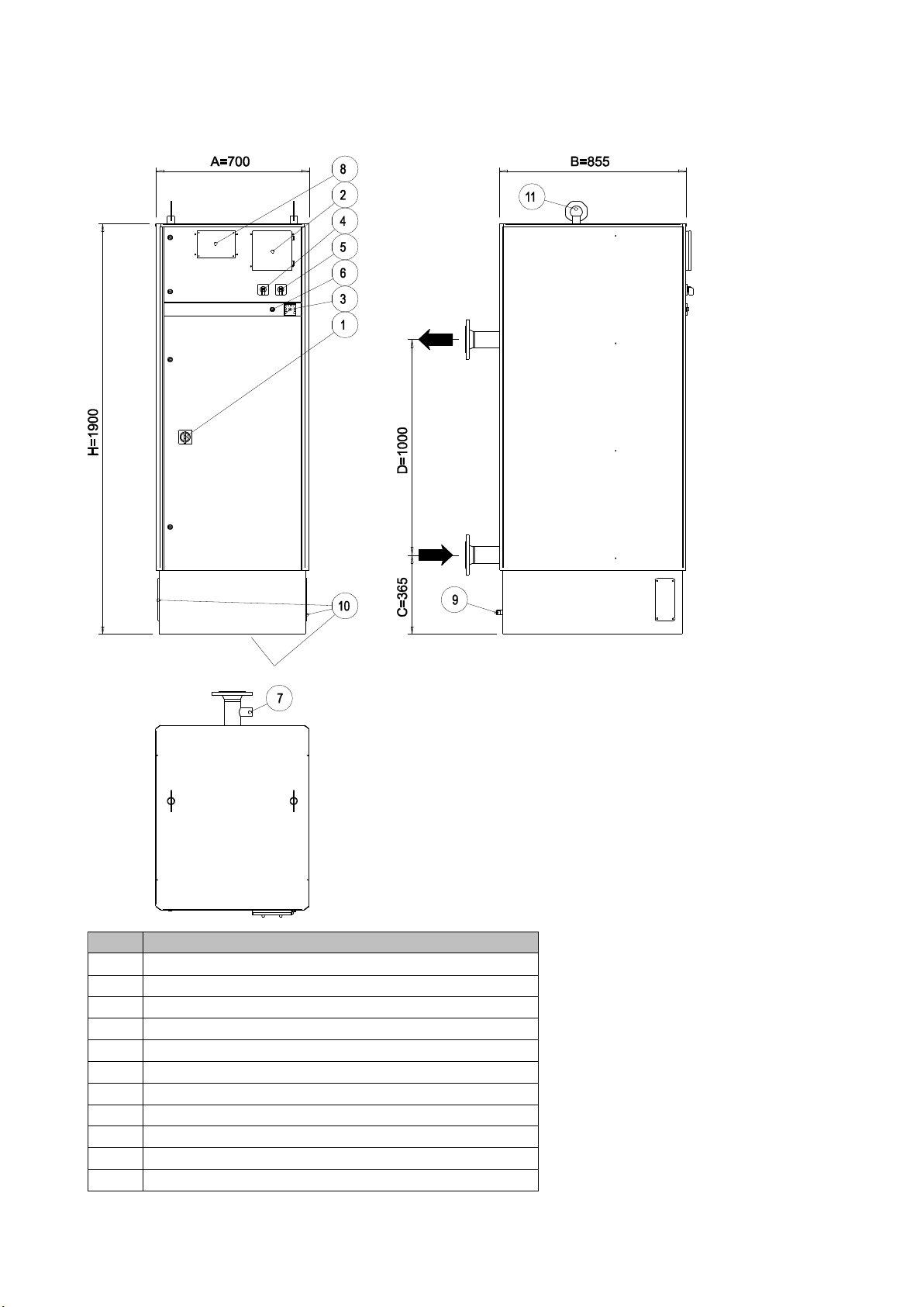
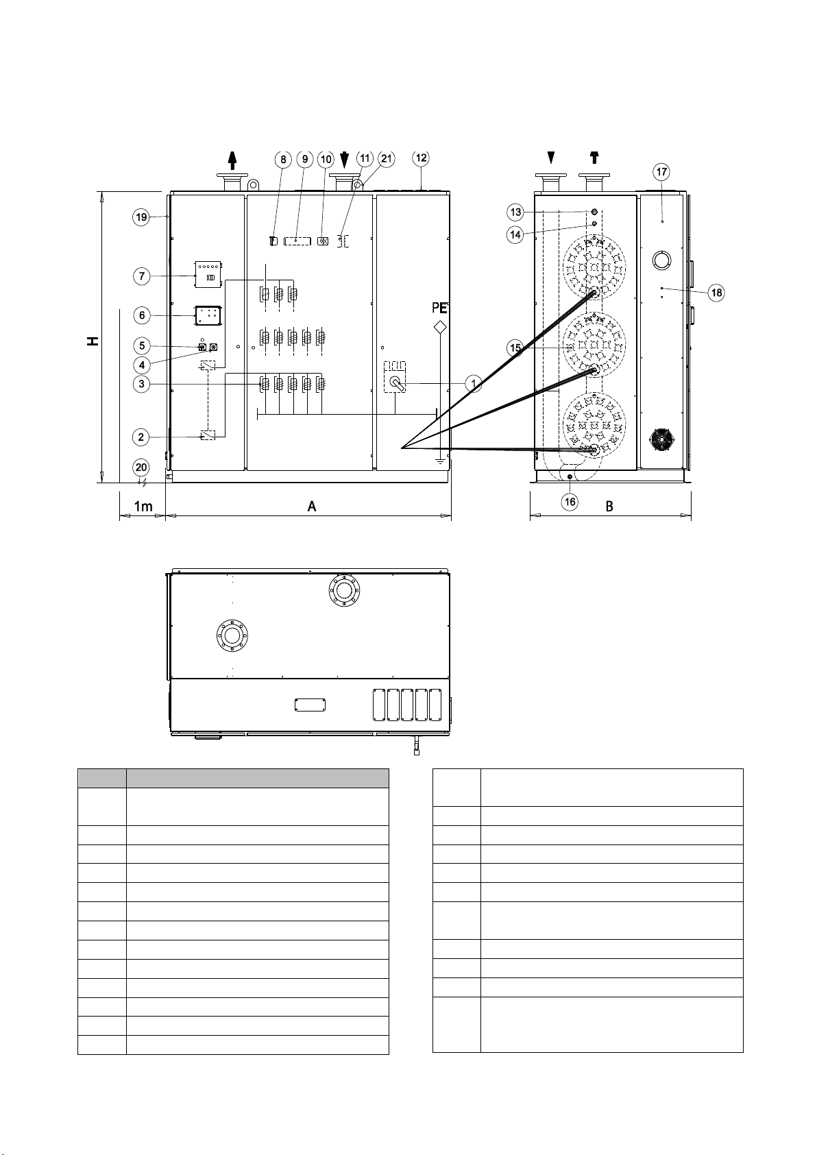
12. Technical data...................................................................................................................................... 36
Technical specifications............................................................................................................................... 36
Electrical properties of FIL-SPL boilers ........................................................................................................ 37
External control voltage (input) values and corresponding power steps in different modes. ................... 38
Status output voltage values and corresponding status data in different modes...................................... 39
Temperature sensor resistance values in different temperatures ............................................................. 40

Recommended circulation pumps............................................................................................................... 41
Pressure drop table ..................................................................................................................................... 42
Electrical circuit diagrams, models of 31 - 112 kW ..................................................................................... 43
Electrical circuit diagrams, models of 150 - 300 kW ................................................................................... 46
Electrical circuit diagrams, models of 400 - 1600 kW ................................................................................. 49

1. Important information
Safety information
This appliance is not intended for use by children or persons, whose physical,
sensory or mental disabilities or lack of experience and knowledge would prevent
the safe use of the appliance, if they are not under the supervision of a person
responsible for ensuring their safety or have been training in the proper use of the
appliance.
Rights to make any design or technical modifications are reserved.
General
This user manual must be left with the customer.
Note! After the main switch has tripped, ensure that the main switch is reset by first positioning the switch
to “0” (off) and then back to “I” (on) position.
Note! When the temperature limiter, dry-boiling preventer or current limit in the main switch are activated,
the main switch is tripped.
Note! Always use original or equivalent spare parts.
Note! Check and tighten the boiler's wire connections after 100 operating hours and then at least once a
year.
Marking
FIL-SPL is CE marked and fulfills IP20.
The CE marking means that Kaukora ensures that the product meets all regulations that are placed on it
based on relevant EU directives. The CE mark is obligatory for most products sold in the EU, regardless
where they are made.
Serial number
The serial number can be found from the type plate at the left side of the boiler, on the top right corner.
Note! Always give the product's serial number when reporting a fault.

Inspection of the installation
Current regulations require the heating installation to be inspected before it is commissioned. The
inspection must be carried out by a suitably qualified person. Fill in the page for information about
installation data.
INSTALLATION INSPECTION
Description
Notes (fill: OK / YES / NO/ NA / write more info)
Heating medium
Water circulation system
installed accordingly
Safety valve installed accordingly
Installations according to HVAC
diagram
System is vented
Pressure of the system
__________ bar
Plumping installation company:
Telephone:
Installer:
Date:
Signature:
______________________________
______________________________
______________________________
______________________________
Electrical connections
Main fuses (of the property)
__________ A
Fuses of FIL-SPL
__________ A
Primary side current transformers
installed
conversion ratio: __________
Secondary side current
transformers installed
Current transformer for
observation of internal power
consumption installed
Power limitation taken into use
Electrical installation company:
Telephone:
Installer:
Date:
Signature:
______________________________
______________________________
______________________________
______________________________
Settings
Max. number of allowable power
steps (Menu 2.1.1 Max)
Step time (Menu 2.1.2 Time)
Max. current limit
(Menu 2.2.1 Max)
Miscellaneous
Serial number
Currently measured boiler
temperature
__________ °C
Functionality tested and approved
Note! The installation inspection must be filled for
meeting requirements for manufacturers guarantee.

2. Delivery and handling
Transport
The FIL-SPL must be transported and stored vertically in a dry place. The FIL-SPL boiler should be lifted only
from the lifting point on top of the boiler.
Physical installation
Mount FIL-SPL boiler on a firm base that can take the weight, preferably on a concrete floor or foundation.
The boiler must be mounted in an upright position and bolted on the floor, preferably in a dry and warm
space with a floor drain.
A clearance of approximately 300-500 mm must be left behind the boiler for pipe connections and for
ventilation. According to safety regulations, at least 1 meter of free space must be left in front of the boiler.
With models from 31.5 to 300 kW, either side of the boiler may be close to a wall. With these models,
approximately 1 meter space should be left above the boiler for possibly replacing resistor elements.
With models from 400 to 1600 kW, there must be left space for possibly replacing resistor elements that
are located on one side that is depending on construction. With these models pipe and electrical
connections are on the top of the boiler and thus requires space.
Note! When selecting mounting location, bear in mind that pipe installations, control valves and other
plumping arrangements needs also space.
Note! Leave enough space for servicing boiler and external circulation pump.
Supplied components
Jäspi current transformers can be ordered as an accessory. The Jäspi current transformers can be used as
secondary current transformers for load monitoring of main fuses or for observation of internal power
consumption for alarm. If both properties are needed, one set of Jäspi current transformers and one extra
Jäspi current transformer must be ordered. The transform ratio of Jäspi current transformers is 300/1.

3. Structure and measures of FIL-SPL boilers
Models of 31 - 112 kW
No.
Name
1
Safety main switch (CB + switch disconnector + trip)
2
Control unit
3
Temperature gauge
4
Control voltage switch
5
Heating mode selection switch
6
Temperature limiter
7
Placeholder for sensor of dry-boiling preventer
9
Connection for draining
10
Placeholder for electrical cables
11
Lifting point

Models of 150 - 300 kW
No.
Name
1
Safety main switch (CB + switch disconnector + trip)
2
Control unit
3
Temperature gauge
4
Control voltage switch
5
Heating mode selection switch
6
Temperature limiter
7
Sensor of dry-boiling preventer
8
Dry-boiling preventing unit
9
Connection for draining
10
Placeholder for electrical cables
11
Lifting point

Models of 400 - 1600 kW
No.
Name
1
Safety main switch
(CB + switch disconnector + trip)
2
Power step contactors
3
Power step fuses
4
Heating mode selection switch
5
Control voltage switch
6
Dry-boiling preventing unit
7
Control unit
8
Backup heating thermostat
9
Connectors
10
Time delay relay
11
Control voltage transformer
12
Placeholder for electrical cables
13
Sensor of dry-boiling preventer
14
Temperature sensors
(limiters and thermostat)
15
Heating elements
16
Connection for draining
17
Temperature gauge
18
Thermostat/temperature limiter
19
Door for heating element service
20
Required space for service of
heating elements
21
Lifting point
A
2000 mm
B
1150 mm
C
1800 mm for 400…800 kW
2000 mm for 801…1200 kW
2400 mm for 1201…1600 kW

4. Pipe connections
General pipe connections
Pipe installation must be carried out in accordance with current norms and directives.
Maximum of 10 bar safety valve must be installed in the supply pipe before any shut-off valve. The safety
valve must be dimensioned so that its blowdown force with steam is equal to the boiler power. The size of
the blowdown pipe cannot be reduced from its nominal size and must be positioned so that the steam
discharge does not cause any personnel injuries or property damage.
When installing pipes, special attention must be given to the installation of safety valves, expansion
installations and possibility for air discharge in the electric boiler discharge pipe. The direction of flow must
be marked on the supply and return pipes.
Note! Any high points in the climate system, must be equipped with air vents.
Note! The pipe systems need to be flushed out before the boiler is connected so that any debris cannot
damage component parts.
Note! The main switch must not be moved to "I" (on) until the system has been filled with water and water
circulation is ensured. Otherwise the temperature limiter, thermostat and the immersion heater etc. can be
damaged.

System diagram
The FIL-SPL electrical boiler consists of resistor elements and control unit. The boiler operates on a flow-
through principle and thus requires an external system that constantly circulates water in the heater.
Recommended external circulation pump can be found from Technical data, Recommended circulation
pumps.
Note! The water circulation in the FIL-SPL boiler must be ensured in all possible cases, unless the boiler is
intentionally shut down with the main switch.
The boiler can be used directly for heating or indirectly to produce hot water for general use.
Typical applications include industry, apartment blocks, row houses or similar. The boiler is suitable for use
as a supplemental/backup heat source for heat pumps.

5. Electrical connections
General
All electrical equipment, except the current sensors are connected and tested at the factory. Internal
connections must never be changed.
Sensor cables to external connections must not be laid closer than 20 cm to high voltage cables
Models up to 300 kW have 5-wire system for main supply
Models from 400 to 1600 kW have 4 wire system for main supply and are equipped with integrated
control voltage transformer
Models from 120 kW have integrated dry-boiling preventer
With models of 31.5 to 300 kW, the main supply can be routed either through a floor drain from
the base of the boiler or as a surface installation through the flanged ports on the sides of the
boiler
With models from 400 to 1600 kW the main supply is to be routed on the top of the boiler
The boiler is to be permanently connected to main supply
See recommended fuse sizes etc. from Technical data, Electrical properties of FIL-SPL boilers
Note! Electrical installation and service must be carried out under the supervision of a qualified electrician.
Cut the current with the main switch before carrying out any servicing. Electrical installation and wiring
must be carried out in accordance with the regulations in force.
Main switch
The FIL-SPL boiler has integrated main switch. The main switch operates as an isolator switch if
temperature limiter or dry-boiling preventer detects an error or in case of overload.
Note! The main switch must not be moved to "I" (on) until the system has been filled with water and water
circulation is ensured. Otherwise the temperature limiter, thermostat and the immersion heater etc. can be
damaged.
Note! After the main switch has tripped, ensure that the main switch is reset by first positioning the switch
to “0” (off) and then back to “I” (on) position.
Control voltage switch
The control voltage switch is for enabling the control voltage for control unit.
Heating mode selection switch
The heating mode selection switch is for selecting whether normal heating mode or backup heating mode
is used. If the heating mode selection switch is on “0” (off) position, the boiler is in disable state.
Note! In backup heating mode only part of the power is available.
External control selection switch
The external control selection switch is used to select whether the boiler is operating independently or is
there some external control used to enable heating, e.g. command from heat pump. If the external control
mode selection switch is on “0” (off) position, the boiler operates independently.
Fuse for control
There is own fuse for control. The fuse is common to control unit and other controlling components such as
temperature limiter, relay controls and backup heating thermostat.

Temperature limiter
The temperature limiter is a safety feature for preventing the boiler of boiling.
Note! Reset the temperature limiter by first removing the shed and the pressing the button using a small
screwdriver. Press the button lightly.
Note! Models over 300 kW have double temperature limiters for safety reasons.
Backup heating thermostat
The backup heating thermostat is for controlling heat of the boiler in backup mode. The thermostat is
locked to 75 °C in the factory.
Connections
Main supply
The size and type of the supply cable is always determined on a project-specific basis according to the used
fuses, the cable lengths, installation method and applicable standards. The main supply is connected
directly to the main switch (phases), to neutral connector (neutral) and to equipment grounding (protective
earth).
Note! Models from 400 to 1600 kW uses 4-wire connection (neutral is not needed).
Mandatory external circulation pump
The FIL-SPL boiler is a flow through heater, and thus requires an external circulation pump for circulating
water in the boiler. While the boiler is enabled and there is possibility to shut off the heating medium
circuit (with for example building automation), the water circulation in the boiler must be guaranteed in
such cases with external circulation pump and piping (see System diagram as an example). The control
voltage of the circulating pump can be taken from X:2 (L), X:N (N) and X:PE (PE).

Optional connections
Outdoor temperature control
The temperature of the boiler can be controlled automatically by measuring result of outdoor temperature
sensor. The outdoor temperature sensor must be connected to X:14 and X:15. Use only Jäspi outdoor
temperature sensor. Locate the temperature sensor in the shade on a wall facing north or north-west for
preventing effect of for example morning sun.
Note! Remember to first enable the property from Menu 4.5 OutdoorComp and to set configurations
accordingly from Menu 1.1.1/2 OutdoorComp.
Note! Sensor cables to external connections must not be laid closer than 20 cm to high voltage cables.
External blocking
The boiler can be forced to disable all electrical power of heating with potential-free closed contact.
Connect the switch to X:10 and X:11. This property can be used for example for power company limitations.
The heating is blocked while the contact is closed.

External on/off control
The boiler can be remotely enabled or disabled with 230 VAC control voltage. This property can be used for
example when the boiler is used as an additional immersion heater within heat pump system. Connect the
external control voltage to X:4 (L) and X:5 (N). The heating is enabled while 230 VAC is connected to the
X:4-5.
Note! The external on/off control needs to be taken into use with external control selection switch.
Note! Remember to add warning label of external control voltage!
0 - 10 V external control
External analogue inputs (0 - 10 V / 20 - 90 °C) can be used for controlling boiler temperature. Note that
external control voltage does not overrule internal settings, and thus for example the max. temperature,
that is set, will be overruling. Connect external 0 - 10 V control voltage to X:8 (+) and X:9 (-).
The external 0 - 10 V control property must be enabled from the software, see Menu 4.3 Input for more
information. Information about voltage levels versus power steps in different modes can be found from
Technical data, External control voltage (input) values and corresponding power steps in different modes.

Load Monitor
Load monitor is used for protecting main fuses of the property. The primary side current transformers must
be located near main fuses of the property. Optimum place would be immediately after power meter. Note
that primary side current transformers should have suitable conversion ratio. The load monitor uses
measured values of Jäspi current transformers (secondary side current transformers) and limits the power
of the boiler while one of the phases has overcurrent. Connect the Jäspi secondary side current
transformers to X:18 (common), X:19, X:20 and X:21.
Note! The minimum area of Jäspi current transformer cables must be 1.5 mm² up to 500 m.
Recommendation is to use shielded cable.
Note! With main fuses (of the property) smaller than 3 x 70 A, the Jäspi current transformers may be used
directly for load monitor.
On the left side of the figure above is connection of relatively small main fuses (< 70 A), when Jäspi current
transformers (TF1-3) can be used directly (depends on the size of the supply cable). On the right side of the
figure is shown the connection when primary side current transformers (TF4-6) are needed and Jäspi
current transformers (TF1-3) are used as secondary side current transformers.
The load monitor property must be enabled and configured accordingly in the software. More information
can be found from Menu 2.2 Current.

Observation of internal power consumption
Connecting 1 primary side current transformer (with a suitable conversion ratio) and a Jäspi secondary side
current transformer to the main supply of electric boiler, allows the control unit to monitor the power
consumed by the boiler. The observation enables activation of an alarm in response to an internal lack of
power in the boiler. (e.g. contactor, fuse or resistor failure). Connect the Jäspi secondary side current
transformer to X:16 and X:17.
Note! With 31.5 kW model, the Jäspi current transformers may be used directly for load monitor.
The observation of internal power consumption property must be enabled and configured accordingly in
the software. More information can be found from Menu 2.3 Effect factor.
0 - 10 V status output
Status data of the FIL-SPL boiler can be shown out via analog voltage message. Connect status output to X:6
(+) and X:7 (-). As a status, following information can be given:
Target temperature value
Measured temperature value
Currently used power step in 15 steps mode
Currently used power step in 7 steps mode
The status output 0 - 10 V property must be enabled and configured accordingly from the software, see
Menu 4.4 Output for more information. Information about voltage levels versus status in different modes
can be found from Technical data, Status output voltage values and corresponding status data in different
modes.

Alarm relay output of control unit
The FIL-SPL boiler can activate a potential free changeover contact when an alarm is detected. Connect an
alarm indication to X:22 (common), X:23 (NC), X:24 (NO). During the alarm, the X:22-24 are connected.
The initial cause of an alarm will be identified on the display. Possible issues that generates an alarm:
Malfunction of the temperature sensor of the boiler
Issue in observation of internal power consumption (needs accessory)
Low supply voltage of control unit (nominal - 10 %)
Note! Remember to add warning label of external control voltage!
Note! The alarm relay output can have maximum load of 2 A (230 V AC) in total.
Alarm relay output of the main switch
The FIL-SPL boiler has an extra alarm relay in the main switch. If the main switch trips for some reason, the
changeover contact in the main switch can be used as an alarm source for example for building
automation. Connect the alarm from the main switch to X:25 and X:26 (NO). During the alarm, the X:25-26
are connected.
Possible issues that generates an alarm:
Overload in the main switch
Temperature limiter
Dry-boiling preventer (models from 120 kW to 1600 kW)
Note! Remember to add warning label of external control voltage!

Status output of control unit
The FIL-SPL boiler can indicate the On/Off status of the control unit. The information can be used for
example in building automation. Connect the status information of the control unit to X:27 and X:28 (NC).
While the control unit has supply voltage the X:27-28 are connected.
Note! Remember to add warning label of external control voltage!
High temperature alarm in switchboard (only with 800-1600 kW models)
The FIL-SPL boiler automatically starts cooling fans if the temperature of the switchboard increases.
However, if the temperature exceeds 50 °C, an alarm will be given. The information can be used for
example in building automation. Connect the alarm information of the high temperature in switchboard to
X:29 and X:30 (NO). While the alarm is activated the X:29-30 are closed.
Note! Remember to add warning label of external control voltage!
Table of contents
Popular Heater manuals by other brands

Silvercrest
Silvercrest SOR 2400 D2 Operation and safety notes

TriStar
TriStar KA-5033 user manual

Air King
Air King 8605 operating instructions

Glowworm
Glowworm Ultimate 3 Installation and maintenance instructions

LivePure
LivePure Turbine Vortex Auto-Duster LP2000HTR manual

Masterpro
Masterpro MHP-135-KFA User's manual & operating instructions