manuals.online logo
Brands
  1. Home
  2. •
  3. Brands
  4. •
  5. ThermoFisher Scientific
  6. •
  7. Microscope
  8. •
  9. ThermoFisher Scientific iN10 User manual

ThermoFisher Scientific iN10 User manual

Procedure: Installation
Title: Installing the iN10/iN10MX
Revision: 09
Procedure # Install-001
ECCN: EAR99
This document contains confidential or proprietary information of Thermo Fisher Scientific. Neither this
document nor the information therein is to be reproduced, distributed, used or disclosed, either in whole or
in part, except as specifically authorized by Thermo Fisher Scientific.
8/3/2020 Page 1 of 61
iN10/iN10MX
MX
Part number: 912A0604/912A0605/912A0804/912A0805
Part description: iN10/iN10MX Integrated Infrared Microscope
Tools required:
 Scissor
 Short handled medium Phillips screwdriver
 Long handled medium Phillips screwdriver
 Flat blade screwdriver
 5/64” balldriver or L-wrench (array alignment)
 Needle nose pliers (iZ10 interface installation)
 Pliers (iZ10 installation)
 3/16” L-wrench (iZ10 installation)
 5/32” balldriver (iZ10 installation)
 Laboratory grade powder-free gloves
 ATR Crystal alignment procedure
 Service test slide
 100um Pinhole slide
Estimated time required: Approximately 4 -12 hours depending on
configuration.
Notes: N/A
Installing the iN10/iN10MX
This document contains confidential or proprietary information of Thermo Fisher Scientific. Neither this
document nor the information therein is to be reproduced, distributed, used or disclosed, either in whole or
in part, except as specifically authorized by Thermo Fisher Scientific.
8/3/2020 Page 2 of 61
Rev
Notes
00 Release.
01
Added step to setting video
properties to include t
urn
ing
off
all
auto
gain
s.
Added step to back-up system parameters.
Moved running a bench status report to the
end of the procedure
.
02 Updated picture and procedure to reflect the new AEM mirror flipper
shipping restraint
.
03 Added remove the array shipping restraint and install the Dewar fill
extender
.
.
Deleted step to verify video calibration parameters from Sync Settings as it
is not necessary
.
Modified step
s as necessary.
Modified mapping steps to contact the factory for IR/Videos displaced over
25
mic
r
ons
.
Changed all number references to coincide with changes.
04
Added Rev 00
information
.
05 Added ECCN number.
Added safety page.
06 Added step to Load other software as applicable.
Added
new
iN10MX part numbers on page 1.
Added
new step.
07 Added array zoom verification.
Modified software loading steps to reflect 1 DVD.
Added step to turn “on” the flat field correction.
Removed
and added steps as necessary to update procedure.
Updated illustrations to reflect new ATR orientation.
08
Added missing text to set
Recommended Scan Speed to
Fast
in step 42.9.
Added note to step 35.2.
09 Added complete ATR alignment procedure.
Installing the iN10/iN10MX
This document contains confidential or proprietary information of Thermo Fisher Scientific. Neither this
document nor the information therein is to be reproduced, distributed, used or disclosed, either in whole or
in part, except as specifically authorized by Thermo Fisher Scientific.
8/3/2020 Page 3 of 61
Important: Prior to performing any replacement procedure, you must read the
Nicolet iN10 Safety Guide. If you do not have the Safety Guide, it is available for
download from the PSE website. If you do not have access to the PSE website,
email international support to request access at
Support.Madison@thermofisher.com
Safety Risks when performing this procedure:
 None
Installing the iN10/iN10MX
This document contains confidential or proprietary information of Thermo Fisher Scientific. Neither this
document nor the information therein is to be reproduced, distributed, used or disclosed, either in whole or
in part, except as specifically authorized by Thermo Fisher Scientific.
8/3/2020 Page 4 of 61
1. If your system was ordered with validation certification, complete this
installation procedure before performing ValPro.
2. Release bands and unwrap the system. The system is shipped with the
main system package and the computer packages wrapped and banded
together. Using a scissor, cut the shipping bands and then remove the plastic
shipping wrap.
IMPORTANT BEFORE UNPACKING THE SYSTEM, ALLOW AT LEAST 24 HOURS FOR
THE SYSTEM TO REACH ROOM TEMPERATURE. EXTREME TEMPERATURE
CHANGES CAN CAUSE CONDENSATION AND PERMANENTLY DAMAGE OPTICAL
COMPONENTS.
3. Remove the computer packages and set them aside.
Installing the iN10/iN10MX
This document contains confidential or proprietary information of Thermo Fisher Scientific. Neither this
document nor the information therein is to be reproduced, distributed, used or disclosed, either in whole or
in part, except as specifically authorized by Thermo Fisher Scientific.
8/3/2020 Page 5 of 61
4. Open the main system shipping box. Using a scissor, cut and remove the
plastic bands that hold the main system box closed. Open the box lid.
5. Remove the upper foam restraint. Inside will be the system enclosed in a
desiccated plastic bag and the accessory box.
6. Lift the cardboard enclosure up and over the system.
Installing the iN10/iN10MX
This document contains confidential or proprietary information of Thermo Fisher Scientific. Neither this
document nor the information therein is to be reproduced, distributed, used or disclosed, either in whole or
in part, except as specifically authorized by Thermo Fisher Scientific.
8/3/2020 Page 6 of 61
7. Remove the accessory box.
8. Open the Accessory box.
9. Remove the top layer of foam. Set aside the “Open Me First” folder.
Unpack the cables, purge hardware, software CD’s, manuals, LN2 thermos
(optional), and hardware joystick (optional).
“Open Me First”
folder
Installing the iN10/iN10MX
This document contains confidential or proprietary information of Thermo Fisher Scientific. Neither this
document nor the information therein is to be reproduced, distributed, used or disclosed, either in whole or
in part, except as specifically authorized by Thermo Fisher Scientific.
8/3/2020 Page 7 of 61
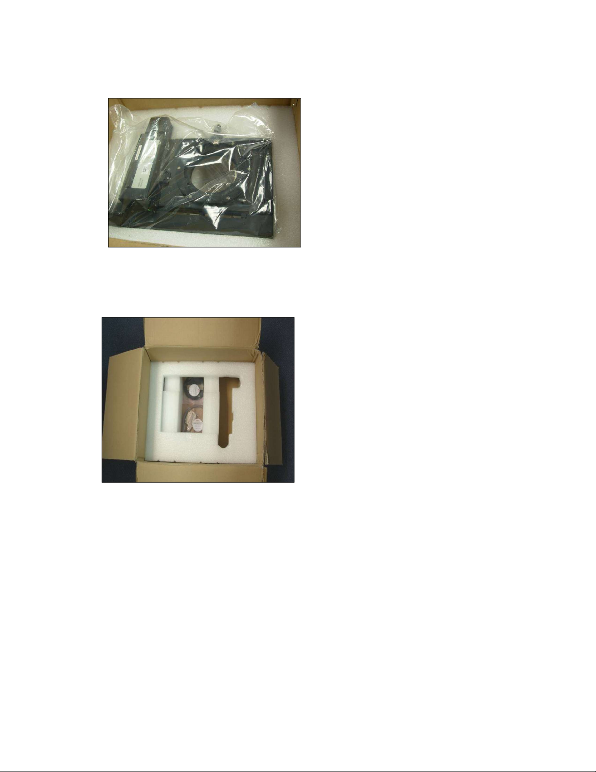
10. Remove the next layer of foam. This will reveal either the manual X-Y
stage or motorized X-Y stage package and up to three additional plastic
cases. The cases will be the iN10 Toolkit (standard), the slide on ATR kit
(optional), and the ValPro Standards (optional). Set the boxes aside and
remove the X-Y stage package.
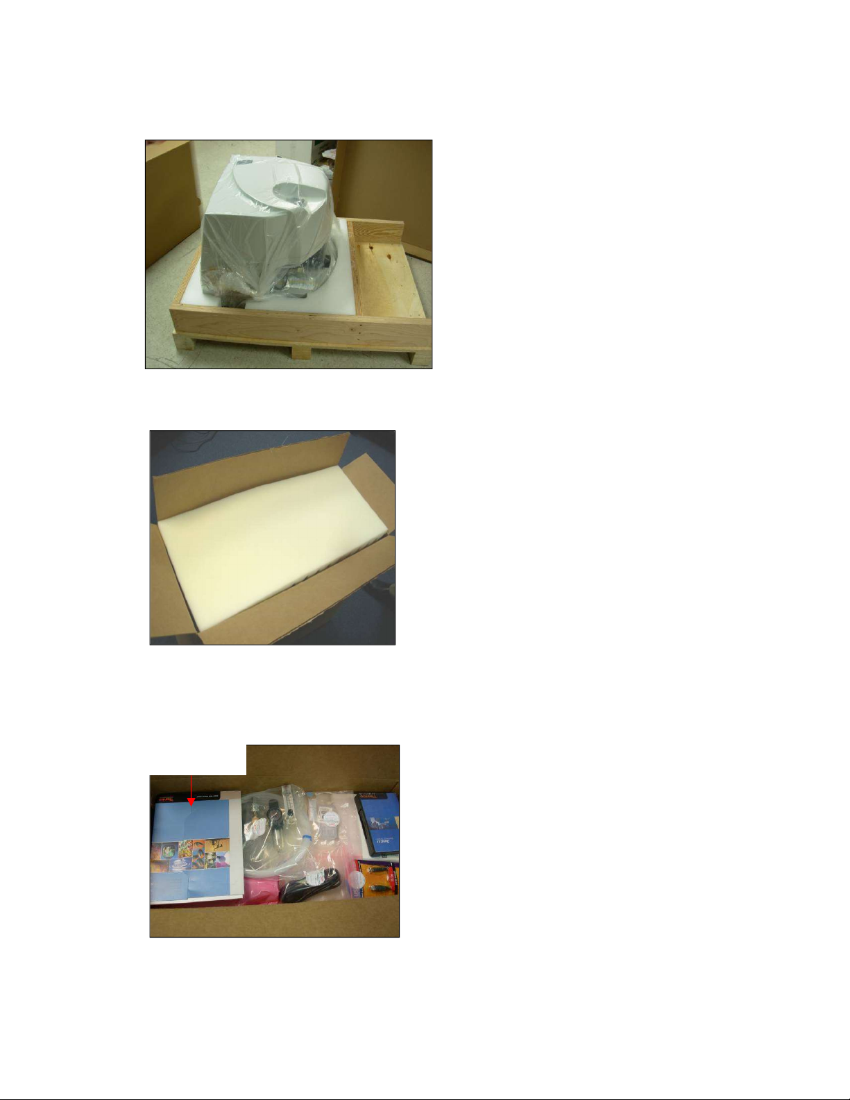
11. Verify all components are present per the packing list (located in the
“Open Me First” folder) and customer order.
12. Prepare the work surface for the instrument.
13. Remove the instrument and set it on the work surface. With one person
on each side of the instrument place hands into the cutouts in the lower foam
restraint and lift the system onto the work surface.
NOTE THE INSTRUMENT WEIGHS APPROXIMATELY 150LBS AND REQUIRES AT
LEAST TWO PEOPLE TO LIFT IT. A PROPER WORK SURFACE MUST BE USED TO
HOLD THE INSTRUMENT. PLEASE REFER TO THE SITE PREPARATION AND SAFETY
MANUAL FOR DETAILS.
Cutouts
Installing the iN10/iN10MX
This document contains confidential or proprietary information of Thermo Fisher Scientific. Neither this
document nor the information therein is to be reproduced, distributed, used or disclosed, either in whole or
in part, except as specifically authorized by Thermo Fisher Scientific.
8/3/2020 Page 8 of 61
14. Remove the plastic bag. Cut and remove the plastic bag and discard the
shipping desiccant packages. Carefully remove the bubble wrap from the
area between the objective and condenser.
15. Remove shipping tape. Carefully remove the tape that holds the condenser
baffle onto the Z stage. This tape is for shipping purposes only. There are
typically three pieces of tape (front, rear, and side).
16. Open the motorized X-Y stage package (optional). If a motorized stage
was not ordered, continue with step 19, otherwise continue with step 17.
Installing the iN10/iN10MX
This document contains confidential or proprietary information of Thermo Fisher Scientific. Neither this
document nor the information therein is to be reproduced, distributed, used or disclosed, either in whole or
in part, except as specifically authorized by Thermo Fisher Scientific.
8/3/2020 Page 9 of 61
17. Remove and unwrap the motorized X-Y stage and set the stage aside.
18. Remove the stage cable and sample insert. Remove the X-Y stage cable
and standard sample insert from under the packing foam and set aside.
Continue with step 20.
19. Un-wrap the manual X-Y stage. Un-wrap the manual X-Y stage. Set the
stage and insert aside.
20. Unpack the iZ10 if applicable, if an iZ10 was not ordered, continue with
step 21. Remove the iZ10 from its shipping box and set it on the work surface
next to the iN10. Remove and discard of any packing materials and then
continue with step 21.
Installing the iN10/iN10MX
This document contains confidential or proprietary information of Thermo Fisher Scientific. Neither this
document nor the information therein is to be reproduced, distributed, used or disclosed, either in whole or
in part, except as specifically authorized by Thermo Fisher Scientific.
8/3/2020 Page 10 of 61
21. If you DO NOT have an iN10MX with imaging option or an iZ10 option,
continue with step 26. If you have an imaging option or an iZ10 option,
continue with step 22.
22. Remove the main cover of the iN10. Using a short handled Phillips
screwdriver, remove the 5 screws from under the top front of the iN10 and
using a long handled screwdriver remove the two screws at the rear base of
the iN10 as shown below. Set the screws aside and lift the cover straight up
to remove it from the base. Set the cover aside.
23. Remove the array detector shipping restraint if applicable and install
the Dewar fill extender (iN10MX with imaging option only). If an array is
not installed, continue with step 24.
Installing the iN10/iN10MX
This document contains confidential or proprietary information of Thermo Fisher Scientific. Neither this
document nor the information therein is to be reproduced, distributed, used or disclosed, either in whole or
in part, except as specifically authorized by Thermo Fisher Scientific.
8/3/2020 Page 11 of 61
24. Attach the iZ10. If an iZ10 was not ordered, continue with step 25.
24.1. Remove the iN10 base cover. Using a short handled Phillips
screwdriver, remove the four screws from the base cover of the
iN10 and set the screws aside.
Carefully lift the cover up being careful not to disturb the contact
alert cable on the Z stage ring and remove the lower cover from the
microscope. Set the cover aside.
24.2. Remove the 3 purge plugs from the base plate of the iN10.
Using needle nose pliers; grasp and pull up on the purge plugs and
remove them from the baseplate.
Installing the iN10/iN10MX
This document contains confidential or proprietary information of Thermo Fisher Scientific. Neither this
document nor the information therein is to be reproduced, distributed, used or disclosed, either in whole or
in part, except as specifically authorized by Thermo Fisher Scientific.
8/3/2020 Page 12 of 61
24.3. Remove the AEM flipper shipping restraint. Using a 5/32”
balldriver, remove the screw and shipping restraint from the AEM
flipper assembly. Store the screw and shipping restraint with the
customer items in case the system needs to be moved in the future.
24.4. Connect the AEM flipper mirror cable.
24.5. Remove the cover from the iZ10. Using a medium Phillips
screwdriver, loosen the 4 screws from the cover of the AEM and lift
up to remove the cover. Set the cover aside.
Remove shipping
restraint
Shipping restraint
Installing the iN10/iN10MX
This document contains confidential or proprietary information of Thermo Fisher Scientific. Neither this
document nor the information therein is to be reproduced, distributed, used or disclosed, either in whole or
in part, except as specifically authorized by Thermo Fisher Scientific.
8/3/2020 Page 13 of 61
24.6. Remove the purge plugs from the iZ10. Using needle nose pliers,
remove the 4 purge plugs from the iZ10. There 2 plugs on the left
edge as depicted below, 1 in the sample compartment and another
in the main compartment approximately center behind the sample
compartment wall.
24.7. Attach the iZ10 to the interface plate. Slide the interface plate
under the iZ10 as shown and using a 3/16” balldriver, attach the
plate to the iZ10 using 4 of the screws from the interface kit.
Installing the iN10/iN10MX
This document contains confidential or proprietary information of Thermo Fisher Scientific. Neither this
document nor the information therein is to be reproduced, distributed, used or disclosed, either in whole or
in part, except as specifically authorized by Thermo Fisher Scientific.
8/3/2020 Page 14 of 61
24.8. Attach the interface plate to the iN10. Tip the iZ10 up from the
right side so the interface plate tips down and align the channel with
the pin under the left side of the iN10.
Carefully slide the plate under the iN10 until the pin is at the end of
travel.
24.9. Attach the interface plate to the iN10. Using the 3 remaining
screws from the interface kit, attach the plate to the iN10 using a
3/16” L-wrench. Use pliers to tighten the screw on the right side of
the firewall.
Pin
Installing the iN10/iN10MX
This document contains confidential or proprietary information of Thermo Fisher Scientific. Neither this
document nor the information therein is to be reproduced, distributed, used or disclosed, either in whole or
in part, except as specifically authorized by Thermo Fisher Scientific.
8/3/2020 Page 15 of 61
24.10. Record the Validation Wheel serial number. If Installation
Certification is being performed, record the Validation Wheel serial
number before proceeding to the next step.
24.11. Remove the beam-hole plug from the left side of the cover of
the iZ10 if applicable. Store the plug with the customer items.
24.12. Reinstall the iZ10 cover.
24.13. Reinstall the base cover on the iN10. Using the screws removed
in step 24.1; reinstall and secure the base cover.
24.14. Remove the external beam-hole plug from the iN10 main cover.
If the external port lens is already installed, continue with step
23.17. If the plug as shown below is installed, using a flat blade
screwdriver, carefully pry and remove the plug from the main cover.
Store the plug with the customer items and continue with step
24.15.
24.15. Put on gloves. Laboratory grade powder-free gloves are
recommended to protect the external port lens from accidental
contamination.
Installing the iN10/iN10MX
This document contains confidential or proprietary information of Thermo Fisher Scientific. Neither this
document nor the information therein is to be reproduced, distributed, used or disclosed, either in whole or
in part, except as specifically authorized by Thermo Fisher Scientific.
8/3/2020 Page 16 of 61
24.16. Install the external port lens assembly into the main cover.
Align the assembly with the hole and gently press on the outer ring
to fully install/seat the lens assembly.
24.17. Re-install the main cover. Using the screws removed in step 22,
secure the main cover.
24.18. Install the purge baffle between the iN10 and iZ10. Squeeze the
baffle together and slide between the covers of the iN10 and iZ10
making sure it is positioned around the cover openings and does
not interfere with the beam.
24.19. Attach the accessory cable. Attach the accessory cable between
the iN10 and iZ10 accessory ports at the rear of the electronic
modules and then continue with step 26.
iZ10 iN10
25. Re-install the main cover. Using the screws removed in step 22, secure the
main cover.
Installing the iN10/iN10MX
This document contains confidential or proprietary information of Thermo Fisher Scientific. Neither this
document nor the information therein is to be reproduced, distributed, used or disclosed, either in whole or
in part, except as specifically authorized by Thermo Fisher Scientific.
8/3/2020 Page 17 of 61
26. Attach the X-Y stage (either manual or motorized). Using a flat blade
screwdriver, turn the quick release knob on the X-Y stage counter-clockwise
~3/4 turn to set the quick release for installation.
26.1. Install the X-Y stage on to Z stage dovetail mount. Slide the
back of the stage on to the dovetail mount so the “tabs” hook under
the mount and then press down on the front of the stage until it
“snaps” into place.
26.2. Set quick release knob to lock. Using a flat blade screwdriver,
turn the quick connect clockwise ~3/4 of a turn to lock the stage on
the dove-mount and then install the stage insert. If you have a
motorized stage, continue with step 26.3. If you have a manual
stage, continue with step 27.
Installing the iN10/iN10MX
This document contains confidential or proprietary information of Thermo Fisher Scientific. Neither this
document nor the information therein is to be reproduced, distributed, used or disclosed, either in whole or
in part, except as specifically authorized by Thermo Fisher Scientific.
8/3/2020 Page 18 of 61
26.3. Attach the stage cable. Attach the stage cable to the left side of
the X-Y stage and lock the cable. Attach the other end of the cable
to the back of the firewall and tighten the thumb screws.
27. Cable the system.
27.1. Unpack the power supply and country specific power cord.
27.2. Attach the power supply. Attach the power cord to the power
supply “brick” and then attach the power supply “brick” to the power
connector to the electronics module at the rear of the iN10. Plug the
power cord into the power outlet. Turn the power on to the iN10.
28. Connect computer components. Connect the monitor(s), mouse, keyboard,
power cord, and any other components per the manufacturer’s instructions.
DO NOT CONNECT THE iN10 USB CABLE TO THE COMPUTER
AT THIS TIME.
29. Turn the power on to the computer.
30. Load software.
30.1. Load OMNIC (Picta) Software. Insert the OMNIC (Picta) Software
DVD and follow the on-screen installation instructions; install .NET
if prompted.
30.2. Load ValPro. (Optional) Insert the ValPro DVD and follow the on-
screen installation instructions (choose EP tests).
30.3. Load other software as applicable (e.g. OMNIC/Picta DS,
libraries, Omnic Specta, etc).
31. Connect the USB cable. Connect the USB cable between the back of the
iN10 electronics module and the computer. The system should be recognized
and the iN10 and camera drivers prompted to load.
Installing the iN10/iN10MX
This document contains confidential or proprietary information of Thermo Fisher Scientific. Neither this
document nor the information therein is to be reproduced, distributed, used or disclosed, either in whole or
in part, except as specifically authorized by Thermo Fisher Scientific.
8/3/2020 Page 19 of 61
32. Configure the software and iN10.
32.1. Launch Omnic Picta. When the Microscope Configuration screen
appears, confirm the Microscope is set to Nicolet iN10, click Save
and then close Omnic Picta.
32.2. Change the Correction Factor. From C:\My Documents\OMNIC
open the OmnicSettings.ini file. Change the UseCorrection factor
from 0 to 1 to turn “on” flat-field-correction and then save and close
the ini file.
32.3. Launch DDiag. If the DDiag icon is not on the desktop; go to
C:\Program Files\Thermo\ddiag and right click on DDiag.exe and
choose Send To, Desktop. Click the DDiag shortcut on the desktop
to launch the iN10 diagnostic program.
32.4. If a motorized X-Y stage is installed, continue with step 32.5. If
a manual X-Y stage is installed, continue with step 32.11.
Microscope model
Installing the iN10/iN10MX
This document contains confidential or proprietary information of Thermo Fisher Scientific. Neither this
document nor the information therein is to be reproduced, distributed, used or disclosed, either in whole or
in part, except as specifically authorized by Thermo Fisher Scientific.
8/3/2020 Page 20 of 61
32.5. Open the Stage Control screen. From the Window drop down
menu choose Stage Control.
32.6. Initialize the X-Y Stage. Click Initialize XY to begin initialization.
32.7. Check the centering of the stage. At the right front corner of the
stage, check that all of the stage plates are flush. If so, continue
with step 32.11, if not continue with 32.8.
32.8. Align Stage plates. From the Window drop down menu choose
Joystick Control. Using the X-Y stage controls, move the stage
until all of the stage plates are flush with each other. Close the
Joystick Control screen when complete.

Other manuals for iN10

1

This manual suits for next models

5

Other ThermoFisher Scientific Microscope manuals

ThermoFisher Scientific Continuµm User manual

ThermoFisher Scientific

ThermoFisher Scientific Continuµm User manual

ThermoFisher Scientific DXR xi User manual

ThermoFisher Scientific

ThermoFisher Scientific DXR xi User manual

ThermoFisher Scientific Nicolet iN5 User manual

ThermoFisher Scientific

ThermoFisher Scientific Nicolet iN5 User manual

ThermoFisher Scientific Continuµm User manual

ThermoFisher Scientific

ThermoFisher Scientific Continuµm User manual

ThermoFisher Scientific iN10 User manual

ThermoFisher Scientific

ThermoFisher Scientific iN10 User manual

Popular Microscope manuals by other brands

Olympus CX21 Maintenance manual

Olympus

Olympus CX21 Maintenance manual

Bresser BioScience instruction manual

Bresser

Bresser BioScience instruction manual

BestScope BS-2030MH4B instruction manual

BestScope

BestScope BS-2030MH4B instruction manual

AmScope AM-1 Series user manual

AmScope

AmScope AM-1 Series user manual

OPTO-EDU A23.0910 instruction manual

OPTO-EDU

OPTO-EDU A23.0910 instruction manual

Invitrogen EVOS XL user manual

Invitrogen

Invitrogen EVOS XL user manual

Optika Italy LAB Series instruction manual

Optika Italy

Optika Italy LAB Series instruction manual

Fluke FI-500 FiberInspector Micro quick start guide

Fluke

Fluke FI-500 FiberInspector Micro quick start guide

Omax MD82ES10 user manual

Omax

Omax MD82ES10 user manual

NetPeppers WFM-100 quick start guide

NetPeppers

NetPeppers WFM-100 quick start guide

STEINDORFF NYMCS-320 user manual

STEINDORFF

STEINDORFF NYMCS-320 user manual

AmScope B110C product manual

AmScope

AmScope B110C product manual

3B SCIENTIFIC PHYSICS 400 1003276 instruction manual

3B SCIENTIFIC PHYSICS

3B SCIENTIFIC PHYSICS 400 1003276 instruction manual

Huvitz HS-5000 SX Operator's manual

Huvitz

Huvitz HS-5000 SX Operator's manual

Olympus AH3 Repair manual

Olympus

Olympus AH3 Repair manual

PCE Instruments PCE-MVM 3D user guide

PCE Instruments

PCE Instruments PCE-MVM 3D user guide

Levenhuk 850B user manual

Levenhuk

Levenhuk 850B user manual

OPTO-EDU A12.1303 instruction manual

OPTO-EDU

OPTO-EDU A12.1303 instruction manual

manuals.online logo
manuals.online logoBrands
  • About & Mission
  • Contact us
  • Privacy Policy
  • Terms and Conditions

Copyright 2025 Manuals.Online. All Rights Reserved.