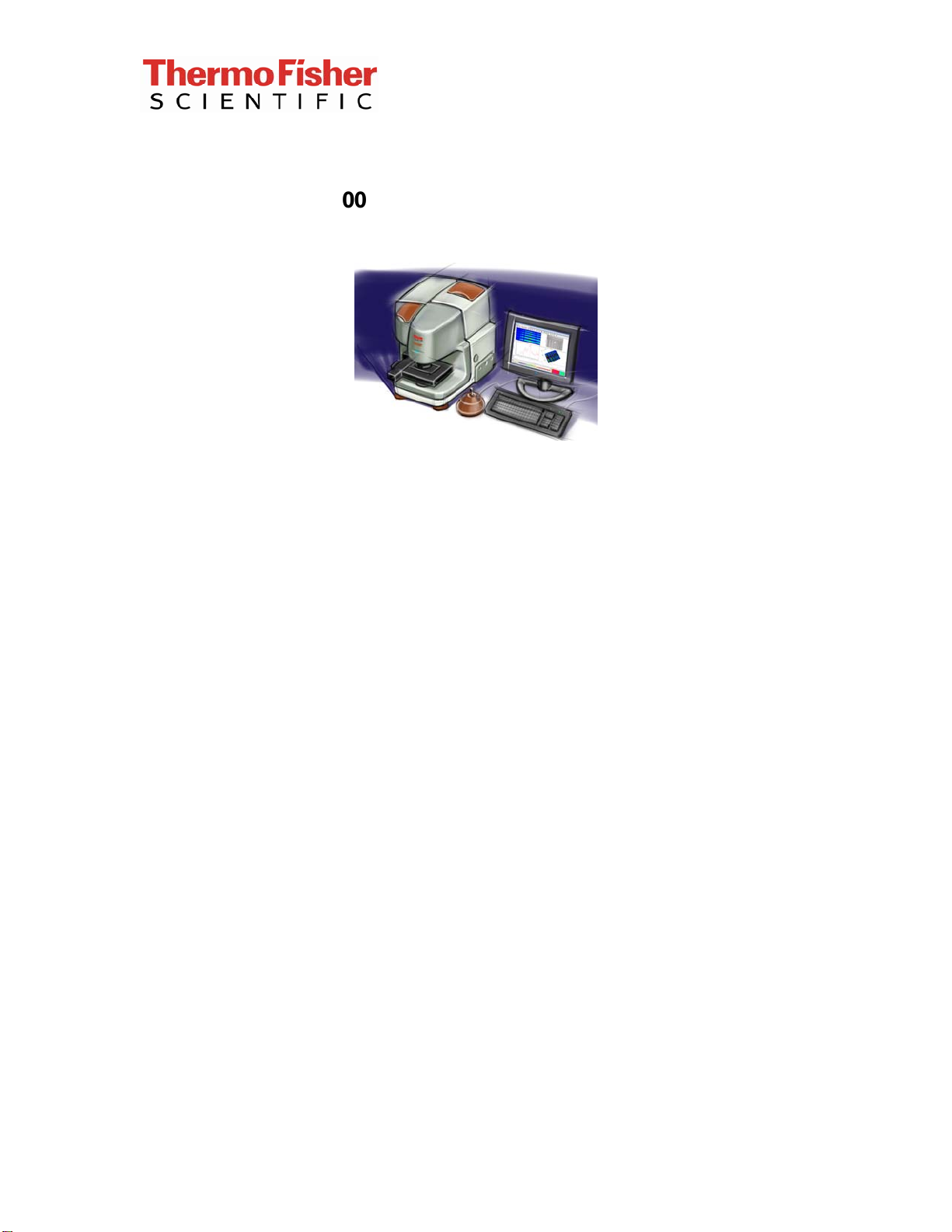
iN10 Installation Checklist
This document contains confidential or proprietary information of Thermo Fisher Scientific. Neither this
document nor the information therein is to be reproduced, distributed, used or disclosed, either in whole or
in part, except as specifically authorized by Thermo Fisher Scientific.
9/25/2012 Page 8 of 10
Attaching the external iZ10
If the system is configured with an external iZ10, follow the latest iN10
installation procedure and remove the external AEM flipper mirror’s
shipping restraint from the iN10 and connect the flipper mirror cable when
instructed.
Follow the iN10 installation procedure and connect the interface plate as
instructed.
Install the external beam port lens into the iN10 main cover.
Remove the purge plug from the cover of the iZ10.
Attach the accessory cable.
Preparing the system and loading OMNIC Picta
There is no shipping restraint on the interferometer.
Remove the array detector shipping restraint if applicable (refer to the
latest iN10 installation procedure); iN10MX systems only.
Install the sample stage (manual or XY).
Attach the stage cable if applicable.
Attach the external power supply.
Set up and connect computer and computer components.
Use the OMNIC Picta installation CD to install OMNIC Picta on the system
computer.
Use the iN10 driver CD to install the iN10 driver on the system computer.
Use the Camera Driver CD to install the camera driver on the system
computer.
Use the ValPro CD to install ValPro on the system computer (if applicable).
Plug the USB 2.0 cable into a USB 2.0 connector on the back of the
system computer. Do not use a USB hub!
Connect the USB 2.0 cable to the connector on the back of the iN10.
Connect the accessory cable from the iZ10 to the iN10 (if applicable).
If included in the shipment, connect the purge regulator and flow meter,
and then set the flow rate according to the information in the instrument
help in Omnic, under the help menu.
Record the aperture calibration parameters.