manuals.online logo
Brands
  1. Home
  2. •
  3. Brands
  4. •
  5. ThermoFisher Scientific
  6. •
  7. Microscope
  8. •
  9. ThermoFisher Scientific Nicolet iN5 User manual

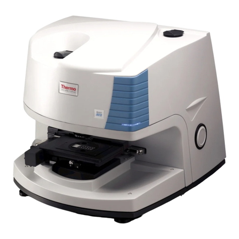
ThermoFisher Scientific Nicolet iN5 User manual

Title: Installing the Nicolet iN5™Microscope
Revision: 03
Procedure: Install-001
ECCN: EAR99
This document contains confidentialorproprietary information of Thermo Fisher Scientific. Neitherthis document nor
the information therein is to be reproduced,distributed,used ordisclosed,either in whole or in part,except as
specifically authorized by Thermo Fisher Scientific.
1/4/2018 Page 1 of 84
Nicolet iN5
Part number: 912A0895 and 912A0922with any of thefollow ingviewing options:
840-287200
840-293700
840-287100
Part description: Nicolet iN5 IR Microscopewith MCTA and Nicolet iN5 IRMicroscopewith DTGSw ith any of the
followingviewing options:
840-287200 – Camera only
840-293700 – Binoc only
840-287100 – Trinoc and Camera
Functional description: Point and Shoot Infrared Microscopecompatiblew ith a Nicolet iS10 or iS50.
Problems associated with this assembly:Alignment, Detector evacuation, Optical contamination, Wear, Damage
Tools required:
Scissors
Box cutter
3-1 Tool
Small flat blade screwdriver
MediumFlat blade screwdriver
3/16 inch balldriver
5/16 inch T-w rench or L-w rench
5/32 inch ball driver
3mmBalldriver
Tw o- 3/32 inch balldriver
5/16 inch balldriver
Tw o- 5/64 inch balldrivers
0.05 inch balldriver
Needle nose pliers
Powder-free gloves
Micrometer/S78 1MM/.01MMReflected (Calibration slide) – Service rep needs to provide/not includedwith iN5
LN2 and proper safety equipment (for MCTA configurations)
Estimated time required:6-8Hours depending onconfiguration
Notes:
1. This procedurecan be used to install both New Nicolet iN5 microscopes and aftermarket installations.
2.
Refer to page 3for software andfirmwarerequirements.
Installing the Nicolet iN5 Microscope
This document contains confidentialorproprietary information ofThermo Fisher Scientific. Neitherthis document nor
the information therein is to be reproduced,distributed,used ordisclosed,either in whole or in part,except as
specifically authorized by Thermo Fisher Scientific.
1/4/2018 Page 2 of 84
Rev
Notes
00
Release.
01
Made corrections per customer audit.
02
Updated note in step 27 to test aperture position repeatability.
Removed gain setting from step 28c.
03
•Added firmware and software requirements to page 3.
•Added new step and comment regarding firmware to step 2.
•Added comment regarding software to step 13.
•Added step to change detector switch settings when connected to an
iS50.
Installing the Nicolet iN5 Microscope
This document contains confidentialorproprietary information ofThermo Fisher Scientific. Neitherthis document nor
the information therein is to be reproduced,distributed,used ordisclosed,either in whole or in part,except as
specifically authorized by Thermo Fisher Scientific.
1/4/2018 Page 3 of 84
Important: Prior to performing this procedure, you must read the Nicolet iN5 Microscope
Site and SafetyGuide. If youdo not have the Safety Guide, it is available for download
from the Knowledge Base. If youdo not have access to the Knowledge Base, email
international support to request access at Support.Madison@thermofisher.com.
Safety Risks when performing this procedure:
•LN2 Exposure
Installing the Nicolet iN5 Microscope
This document contains confidentialorproprietary information ofThermo Fisher Scientific. Neitherthis document nor
the information therein is to be reproduced,distributed,used ordisclosed,either in whole or in part,except as
specifically authorized by Thermo Fisher Scientific.
1/4/2018 Page 4 of 84
1. This procedure assumes the computer, spectrometer software and iS10 or
iS50 have been installed including the removal of all shipping restraints.
2. Prepare and test the spectrometer.
a. Autotune the spectrometer and ensure it passes the Performance Test
and/or ValPro as applicable.
b. If the spectrometer is a Nicolet iS50, ensure firmware 1.15 or greater is
installed on the OBC board,otherwise update firmware.
Note Existing iS50’s inthe field must be upgraded to firmware version1.15
or greater for iN5 compatibilityand beampath recognition.
3. Turn the spectrometer OFF.
4. Unpack the iN5.
a. Open the shipping container, remove the top tray and gently set the
tray on the floor or a tabletop.
The top tray contains software, sensitive optical components and other parts
for the Nicolet iN5. Use caution when removing the tray.
b. Remove all parts from the top tray and set the parts aside.
Installing the Nicolet iN5 Microscope
This document contains confidentialorproprietary information ofThermo Fisher Scientific. Neitherthis document nor
the information therein is to be reproduced,distributed,used ordisclosed,either in whole or in part,except as
specifically authorized by Thermo Fisher Scientific.
1/4/2018 Page 5 of 84
c. Remove the secondary tray.
The secondary tray contains accessories.
d. Remove the thermos and accessory cases from the tray and set aside.
e. Carefully lift the enclosure box straight up to release it from the bottom
tray and set aside.
Installing the Nicolet iN5 Microscope
This document contains confidentialorproprietary information ofThermo Fisher Scientific. Neitherthis document nor
the information therein is to be reproduced,distributed,used ordisclosed,either in whole or in part,except as
specifically authorized by Thermo Fisher Scientific.
1/4/2018 Page 6 of 84
f. Remove the white foam block from the top of the iN5 and set aside.
g. Carefully lift the iN5 from the lower tray and set on a flat, sturdy surface.
h. Remove the plastic bag from the iN5.
5. Prepare the iN5 for installation.
a. Carefully remove the blue tape from the stage assembly and discard.
Then move the Z stage up slightly, remove the white foam or bubble wrap
from the stage assembly and discard.
Installing the Nicolet iN5 Microscope
This document contains confidentialorproprietary information ofThermo Fisher Scientific. Neitherthis document nor
the information therein is to be reproduced,distributed,used ordisclosed,either in whole or in part,except as
specifically authorized by Thermo Fisher Scientific.
1/4/2018 Page 7 of 84
b. Remove the blue tape from the binoc/trinocular dovemount shown
below and the blue tape and red cap from purge extension tube (not
shown) and discard.
c. Check the iN5 for damage. If damage is apparent, stop here and contact
the factory otherwise continue with step 5d.
d. Set the iN5 on the tabletop approximately 3 feet from the right-side of
the spectrometer.
e. Discard all packing materials.
6. Prepare the Nicolet iS10. If you do not have an iS10, continue with step 8.
a. Release the Smart-Omni sample accessory by turning the latch at the
top-back of the assembly approximately 45°counter clock-wise.
Locked Unlocked
Installing the Nicolet iN5 Microscope
This document contains confidentialorproprietary information ofThermo Fisher Scientific. Neitherthis document nor
the information therein is to be reproduced,distributed,used ordisclosed,either in whole or in part,except as
specifically authorized by Thermo Fisher Scientific.
1/4/2018 Page 8 of 84
b. Lift straight-up on the accessory to remove it from the iS10 and set the
accessory aside.
c. Remove the accessory tray by pulling straight-out from the front of the
system and set the tray aside.
d. Open the cover on the top left-side of the iS10 and remove the 3-1 tool;
close the cover.
Installing the Nicolet iN5 Microscope
This document contains confidentialorproprietary information ofThermo Fisher Scientific. Neitherthis document nor
the information therein is to be reproduced,distributed,used ordisclosed,either in whole or in part,except as
specifically authorized by Thermo Fisher Scientific.
1/4/2018 Page 9 of 84
e. Using the Phillips tip, loosen the 2 captive cover screws on the front
corners of the iS10 and at each corner on the back of the iS10.
Loosen two front captive screws
Loosen two back captive screws
f. Remove the iS10 main cover by lifting straight-up and set the cover
aside.
Installing the Nicolet iN5 Microscope
This document contains confidentialorproprietary information ofThermo Fisher Scientific. Neitherthis document nor
the information therein is to be reproduced,distributed,used ordisclosed,either in whole or in part,except as
specifically authorized by Thermo Fisher Scientific.
1/4/2018 Page 10 of 84
7. Unpack the iN5 interface bracket and connect to the iS10.
a. Remove the interface bracket with screws from the plastic bag.
b. Remove the tape from the arm of the bracket to release the bag of 4-
mounting screws; ensure that the locator pin does not stick to the tape.
Remove the tape from the left locator pin ensuring that the pindoes not stick
to the tape. If so, reinsert [the flat side] of the pin(s) into the hole(s).
c. Carefully open the bag of mounting screws and set the screws aside.
d. Place the interface next to the right-side of the iS10. Align the channel in
the interface to the locator pin under the iS10 baseplate at approximate
center.
Installing the Nicolet iN5 Microscope
This document contains confidentialorproprietary information ofThermo Fisher Scientific. Neitherthis document nor
the information therein is to be reproduced,distributed,used ordisclosed,either in whole or in part,except as
specifically authorized by Thermo Fisher Scientific.
1/4/2018 Page 11 of 84
e. Slide the interface toward the iS10 until the end of the channel is fully
engaged with the locator pin.
f. Using a needle nose plier, remove the purge plugs from the iS10 at the
following locations, see below and on the following page. Set purge
plugs with the customer parts.
Remove plug from sample compartment
Remove plugs fromright edge of iS10 baseplate
Installing the Nicolet iN5 Microscope
This document contains confidentialorproprietary information ofThermo Fisher Scientific. Neitherthis document nor
the information therein is to be reproduced,distributed,used ordisclosed,either in whole or in part,except as
specifically authorized by Thermo Fisher Scientific.
1/4/2018 Page 12 of 84
Remove plug from main bench at location shown
g. Secure the interface. Using a 3/16 inch balldriver and the mounting screws
setaside instep 7c, loosely thread all 4 screws into the locations shown
below and then tighten all 4 screws to secure the interface to the iS10. See
below and on the following page.
Install screw in sample compartment
Install screws in right edge of iS10 baseplate
Installing the Nicolet iN5 Microscope
This document contains confidentialorproprietary information ofThermo Fisher Scientific. Neitherthis document nor
the information therein is to be reproduced,distributed,used ordisclosed,either in whole or in part,except as
specifically authorized by Thermo Fisher Scientific.
1/4/2018 Page 13 of 84
Install screw in main bench at location shown
h. If installing a new iS10 motorized external beam mirror on an existing
iS10, install it now otherwise continue with step 7i.
i. Reinstall the iS10 main cover, accessory tray and sample accessory by
reversing steps 6a-6f and then continue with step 10.
Installing the Nicolet iN5 Microscope
This document contains confidentialorproprietary information ofThermo Fisher Scientific. Neitherthis document nor
the information therein is to be reproduced,distributed,used ordisclosed,either in whole or in part,except as
specifically authorized by Thermo Fisher Scientific.
1/4/2018 Page 14 of 84
8. Prepare the Nicolet iS50.
a. Release the iS50 sample compartment cover by opening the cover and
turning the latch approximately 45°clock-wise.
Locked Unlocked
b. Lift straight-up on the cover to remove it from the iS50 and set the
cover aside.
Installing the Nicolet iN5 Microscope
This document contains confidentialorproprietary information ofThermo Fisher Scientific. Neitherthis document nor
the information therein is to be reproduced,distributed,used ordisclosed,either in whole or in part,except as
specifically authorized by Thermo Fisher Scientific.
1/4/2018 Page 15 of 84
c. Using a medium flat-blade screw driver, remove the four screws from
the sample compartment plate. Thenremove the sample compartment
plate from the iS50 and set the plate and screws aside.
Remove four screws
Remove sample compartment plate
Installing the Nicolet iN5 Microscope
This document contains confidentialorproprietary information ofThermo Fisher Scientific. Neitherthis document nor
the information therein is to be reproduced,distributed,used ordisclosed,either in whole or in part,except as
specifically authorized by Thermo Fisher Scientific.
1/4/2018 Page 16 of 84
d. Using a medium flat-blade screwdriver, loosen the four latches on the
iS50 main cover, lift straight up to remove the cover and set the cover
aside.
Loosen four latches and remove the cover
9. Unpack the iN5 interface bracket and connect to the iS50.
a. Remove the interface bracket with screws from the plastic bag.
b. Remove the tape from the arm of the bracket to release the bag of 3-
mounting screws being careful that the locator pin does not stick to the
tape. Also remove the tape from the left locator pin being careful the
pin does not stick to the tape. If so, reinsert [the flat side] of the pin(s)
into the hole(s).
Installing the Nicolet iN5 Microscope
This document contains confidentialorproprietary information ofThermo Fisher Scientific. Neitherthis document nor
the information therein is to be reproduced,distributed,used ordisclosed,either in whole or in part,except as
specifically authorized by Thermo Fisher Scientific.
1/4/2018 Page 17 of 84
c. Carefully open the bag of mounting screws and set the screws aside.
d. Connect the iS50 touch point extension cable to the interface.
e. Place the interface next to the right-side of the iS50. Align the channel in
the interface to the locator pin under the iS50 baseplate located left of center.
Installing the Nicolet iN5 Microscope
This document contains confidentialorproprietary information ofThermo Fisher Scientific. Neitherthis document nor
the information therein is to be reproduced,distributed,used ordisclosed,either in whole or in part,except as
specifically authorized by Thermo Fisher Scientific.
1/4/2018 Page 18 of 84
f. Slide the interface toward the iS50 until the end of the channel is fully
engaged with the locator pin.
g. Wearing powder-free gloves gently move the passport mirror to the
right side to access the purge screw.
If installing a new passport mirror on an existing iS50, remove the
purge screw and then install the new passport mirror.
Installing the Nicolet iN5 Microscope
This document contains confidentialorproprietary information ofThermo Fisher Scientific. Neitherthis document nor
the information therein is to be reproduced,distributed,used ordisclosed,either in whole or in part,except as
specifically authorized by Thermo Fisher Scientific.
1/4/2018 Page 19 of 84
h. Using a 5/32 inch balldriver, remove the two purge screws from the
iS50 at the following locations. Set all purge screws with the customer
parts.
Remove purge screw from sample compartment
Remove purge screw that is accessible
through the passport mirror baseplate
or where the mirror would be installed
Installing the Nicolet iN5 Microscope
This document contains confidentialorproprietary information ofThermo Fisher Scientific. Neitherthis document nor
the information therein is to be reproduced,distributed,used ordisclosed,either in whole or in part,except as
specifically authorized by Thermo Fisher Scientific.
1/4/2018 Page 20 of 84
i. Secure the interface. Using a 5/32 inchballdriver and the mounting screws
setaside instep 9c, loosely thread the 2 screws into the locations shown
below and then tighten the screws to secure the interface to the iS50.
Install short screw in sample compartment
Install long screw through the passport mirror baseplate
j. Reinstall the iS50 main cover, sample compartment plate and sample
compartment cover by reversing steps 8a-8d and then continue with
step 10.

This manual suits for next models

5

Other ThermoFisher Scientific Microscope manuals

ThermoFisher Scientific iN10 User manual

ThermoFisher Scientific

ThermoFisher Scientific iN10 User manual

ThermoFisher Scientific Continuµm User manual

ThermoFisher Scientific

ThermoFisher Scientific Continuµm User manual

ThermoFisher Scientific DXR xi User manual

ThermoFisher Scientific

ThermoFisher Scientific DXR xi User manual

ThermoFisher Scientific iN10 User manual

ThermoFisher Scientific

ThermoFisher Scientific iN10 User manual

ThermoFisher Scientific Continuµm User manual

ThermoFisher Scientific

ThermoFisher Scientific Continuµm User manual

Popular Microscope manuals by other brands

GRUNDIUM OCUS user guide

GRUNDIUM

GRUNDIUM OCUS user guide

Olympus BX63 instructions

Olympus

Olympus BX63 instructions

Leica M500 N Service manual

Leica

Leica M500 N Service manual

BestScope BS-6020RF user manual

BestScope

BestScope BS-6020RF user manual

Accu-Scope EXC-120 SERIES manual

Accu-Scope

Accu-Scope EXC-120 SERIES manual

Westlab M-100F instruction manual

Westlab

Westlab M-100F instruction manual

Kingfisher FiberSafe KI6600 Series user guide

Kingfisher

Kingfisher FiberSafe KI6600 Series user guide

Leica SP8 manual

Leica

Leica SP8 manual

Bresser 300X operating instructions

Bresser

Bresser 300X operating instructions

Levenhuk DTX 350 LCD user manual

Levenhuk

Levenhuk DTX 350 LCD user manual

Celestron Professional 44108 instruction manual

Celestron

Celestron Professional 44108 instruction manual

Auxilab Zuzi 101 manual

Auxilab

Auxilab Zuzi 101 manual

LW Scientific VFA-12 Specifications

LW Scientific

LW Scientific VFA-12 Specifications

Olympus DP22 instructions

Olympus

Olympus DP22 instructions

Cole Parmer MSU-600 Series Installation and operating instructions

Cole Parmer

Cole Parmer MSU-600 Series Installation and operating instructions

Extech Instruments MC108 user guide

Extech Instruments

Extech Instruments MC108 user guide

3B SCIENTIFIC PHYSICS 1005434 instruction manual

3B SCIENTIFIC PHYSICS

3B SCIENTIFIC PHYSICS 1005434 instruction manual

Levenhuk DTX 300 LCD user manual

Levenhuk

Levenhuk DTX 300 LCD user manual

manuals.online logo
manuals.online logoBrands
  • About & Mission
  • Contact us
  • Privacy Policy
  • Terms and Conditions

Copyright 2025 Manuals.Online. All Rights Reserved.