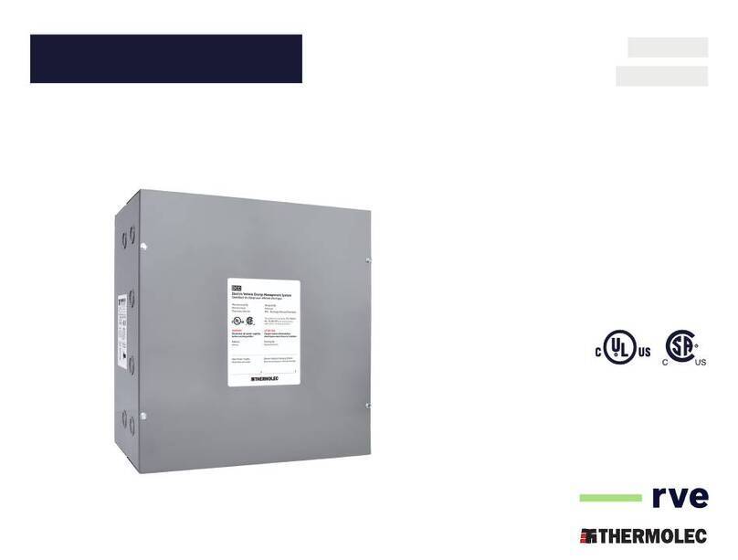
Thermolec DCC-9-BOX User manual

1
INSTALLATION MANUAL
MANUEL D’INSTALLATION MAIN POWER SUPPLY
120/240-208V, Single Phase
60A - 70A - 80A - 90A - 100A - 125A
ALIMENTATION PRINCIPALE
120/240-208V, Monophasé
60A - 70A - 80A - 90A - 100A - 125A
APPROVED MARKET
North America
MARCHÉ AGRÉÉ
Amérique du Nord
MODELS MODÈLES
DCC-9-BOX, DCC-9-BOX-3R, DCC-9-BOX3, DCC-9-BOX6
V5.5
IFRANÇAISI
IENGLISHI
Read and save these instructions
Lire et garder ces instructions
Electric Vehicle Energy
Management System (EVEMS)
Contrôleur de charge pour véhicules électriques
Manufactured by
Manufacturé par
Designed by
Design par
DCC-9-BOX

2

3
TABLE OF CONTENTS
About This Manual 3
Safety Information 4
Specifications 5
Characteristics 5
DCC-9-BOX and DCC-9-BOX-3R 7
Typical Installation 8
DCC Installation 8
Maintenance 9
Internal Components 9
DCC-9-BOX3 and DCC-9-BOX6 11
Typical Installation 12
DCC Installation 12
Maintenance 13
Dimensions 14
IENGLISHI ABOUT THIS MANUAL
ERRORS AND INACURACIES
For any inaccuracy or omission, or to forward any general comments or
suggestions concerning the quality of this manual, please send an email
to suppor[email protected]
COPYRIGHTS AND TRADE NAMES
All information’s in this manual are subject to copyright protection and
other intellectual property protection of THERMOLEC LTÉE. / RECHARGE
VÉHICULE ÉLECTRIQUE and its licensors.This installation manual cannot
be modified, reproduced or copied without a prior written authorisation
from THERMOLEC LTÉE. / RECHARGE VÉHICULE ÉLECTRIQUE and
its licensors. Additional information’s are available on request. The
following logos are trade names or trademarks of THERMOLEC LTÉE. /
RECHARGE VÉHICULE ÉLECTRIQUE in the United States and in Canada.
DCC – EVEMS
All other trade names mentioned in this document are the property of
their respective owners and their uses in this manual does not means
a sponsorship or approval of the product. The use of any trade name
shown in this document is strictly forbidden.
In this document, the terms DCC – EVEMS and DCC are equivalent.

4
SAFETY INFORMATION
This document describes important safety instructions which must be
followed during installation, maintenance and application of the DCC –
Electric Vehicle Energy Management System (EVEMS).
Warning
Read all instructions prior using this
product.
Always disconnect the DCC – EVEMS
power supply before any works.
Use only the DCC – EVEMS by following
the technical specifications indicated in
this installation manual.
Do not install the DCC – EVEMS nearby
inflammable materials, explosives or
fuels, chemical products and vapors.
Never spray the DCC – EVEMS with
water or any other liquids.
Stop using the DCC – EVEMS
immediately if defective, cracked, broken
or damaged.
Never try to modify, repair or dismantle
the DCC – EVEMS. Please contact the
manufacturer for any malfunction.
Never insert a sharp object inside the
DCC – EVEMS at the risk of causing
damages to the components.
Any improper use of the DCC – EVEMS
could result in serious injuries which
may cause death.
For a vertical installation on a wall, refer
to the information’s on the enclosure for
the choice of mounting position.
Precautions
Any improper use of the DCC – EVEMS
can cause damages and premature
wear of the components, which voids
the warranty.
Operating temperature:-22 °F to 113 °F
( -30 °C to 45 °C )
Storage temperature:-4 °F to 158 °F
( -20 °C to 70 °C ).
The installation of the DCC – EVEMS
must be done in accordance with the
latest local electrical code requirements.
Notes
It is recommended to schedule the
charging of the vehicle during hours of
low electrical consumption to minimize
interruptions to the electric charging
station.
Always check that the DCC – EVEMS is
adequately fixed to the wall or ceiling or
in a location to avoid any damages.
Not limited to compatibility with electric
vehicle charging stations, this product
can be installed with resistive loads
of up to 60A and inductive loads of up
to 40A.
It is the installer’s responsibility to
make sure that the electric power
source is adequate for the use of the
DCC – EVEMS.
Do not use any cleaning solvents to
clean the DCC – EVEMS.
Limited warranty
1RECHARGE VÉHICILE ÉLECTRIQUE
warrants the integrated controls
against any defects for a period of
one year from the shipping date. The
warranty is limited to the equipment
and components supplier by
RECHARGE VÉHICULE ÉLECTRIQUE
2In case of incorrect installation,
inappropriate use or repairs done by
unauthorized personnel by RECHARGE
VÉHICULE ÉLECTRIQUE, the warranty
will be automatically void.
3 RECHARGE VÉHICULE ÉLECTRIQUE
undertakes to repair or replace, at
site or at the manufacturing location,
at his option, the defective material
only after an evaluation made by its
representative.
4 RECHARGE VÉHICULE ÉLECTRIQUE
will not be held liable for damages or
delays and will not be required to pay
transport cost of the EVEMS said to
be defective.
5RECHARGE VÉHICULE ÉLECTRIQUE.
shall not be liable for any indirect
damages or delays caused by faulty
workmanship or materials.
No indemnity will be paid for repairs,
replacements or modifications without
a prior written consent supplied by
RECHARGE VÉHICULE ÉLECTRIQUE
6Any control device or accessory
supplied with the DCC – EVEMS to be
installed or connected remotely from
the EVEMS will be guaranteed by the
manufacturer only under the special
conditions mentioned in paragraph 5.
7The components supplied for repairs
are guaranteed for the remaining of
the warranty on the original product
or 90 days. The longest period will
prevail.
8All repairs made at the RECHARGE
VÉHICULE ÉLECTRIQUE plant are
guaranteed for 30 days from the date
of repairs.

5
SPECIFICATIONS
DCC-9-BOX is a splitter box specifically designed to make a building’s
electrical infrastructures fully ready for electric vehicles at the lowest
possible price.
For bundled installations, taller versions (BOX3 and BOX6) can house 3
or 6 DCC PCBs in order to maximise space usage.
MODELS DIMENSIONS*TOTAL WEIGHT*
(H" x W" x D")
DCC-9-BOX 12" x 12" x 7.5" 11 lb (4,99 kg)
DCC-9-BOX-3R 14" x 13" x 8" 12 lb (5,44 kg)
DCC-9-BOX3 45" x 14" x 9" 40.5 lb (18,37 kg)
DCC-9-BOX6 78" x 14" x 9" 81 lb (36,74 kg)
Voltage and wiring 240/208V AC single phase: L1, L2,
Neutral, Ground.
Terminals size up to 2/0 (CU/AL)
Max torque L1, L2, Neutral: 120 in-lbf
Ground: 50 in-lbf
Certifications
*Approximative and can change without notice. V6
CHARACTERISTICS
CONDITIONS FOR APPLICATION
The DCC-9 is an Energy Management System specially designed to allow
the connection of an EV Charger to be connected to a power source
without affecting load calculation.
INSTALLATIONS TYPES
- Group installation
- Wall installation
- Ceiling installation
The DCC-9-BOX6 and DCC-9-BOX3 can also be installed vertically
on the floor.
MAIN POWER SUPPLY (CB)
The DCC-9-BOX can be powered by a 240/208V AC single phase source,
max 125A. The following options are offered by each DCC model:
MODELS MAIN POWER SUPPLY
60A 70A 80A 90A 100A 125A 150A 200A
DCC-9-BOX
DCC-9-BOX-3R
DCC-9-BOX3
DCC-9-BOX6
SEE
DCC-11

6

7
AND
DCC-9-BOX
DCC-9-BOX-3R

8
DCC-9-BOX & DCC-9-BOX-3R
DCC INSTALLATION
STEP 1: CHECK THE PACKAGE CONTENTS
1 x DCC-9-BOX
or 1 x DCC-9-BOX-3R
1 x Ceiling
mounting support 1 x Installation
manual
STEP 2: PREPARATIONS FOR INSTALLATION
1. Disconnect the main power
2. Select the DCC intended location.
The DCC can be mounted:
- on a ceiling
- on a wall
NOTE: The DCC controller must be mounted so that the nameplate
remains visible at all times.
Do not install the DCC:
- Outdoor, unless the DCC is ordered with our NEMA 3R enclosure.
- In a location with high level of risk.
- Nearby inflammable materials, explosives or fuels, chemical
products and vapors.
INSTALLATION VIDEO
To access our installation video,
visit our website www.rve-usa.com/products/dcc-box/
TYPICAL INSTALLATION
NOTES
For outdoor installation, use our NEMA 3R enclosure
(DCC-9-BOX-3R).
DCC-9 with
METER STACK
DCC-9 with
SUB PANEL
FOR HOMES FOR CONDOS
by
EV Charger
Main
Disconnect
Panel
ELECTRICAL INFRASTRUCTURES CHARGING
INFRASTRUCTURES
DCC-9 with
MAIN DISCONNECT
Electrical
Meter
DCC-9
by
DCC-9 with
SUB PANEL
Sub Panel
Main Panel
Electrical
Meter
EV Charger
ELECTRICAL INFRASTRUCTURES CHARGING
INFRASTRUCTURES
DCC-9
by
CHARGING
INFRASTRUCTURES
DCC-9 with
Meter Stack
Meter Stack
Main Breaker
Panel of the Unit
EV Charger
ELECTRICAL INFRASTRUCTURES
DCC-9
DCC-9 with
MAIN DISCONNECT

9
DCC-9-BOX & DCC-9-BOX-3R
STEP 5: SECURE AND ENERGIZE
1. Secure: Put the cover back.
2. Energize: Supply electrical power to the DCC.
STEP 6: IDENTIFICATION
1. Register all the information of the charging station owner
(address and parking space) in the space provided on the cover.
2. Register all configuration settings of the main power supply
(essential load) in the space provided on the cover.
MAINTENANCE
Do not use any cleaning solvents to clean the DCC.
INTERNAL COMPONENTS
3. Before installation, check the DCC mounting position.
Wall installation
Refer to the information on the
enclosure to insure proper
installation.
Ceiling installation
The installation may be done
in any direction.
WARNING
Warranty automatically void if the DCC is installed incorrectly.
STEP 3: INSTALLATION
Ceiling installation
1. Remove the 4 cover screws.
2. Fix the ceiling mounting support on the DCC.
3. Lift the DCC using the ceiling mounting support.
4. Position the DCC at the intended location.
5. Fix the DCC with the anchors for the type of surface.
6. Check that the DCC is adequately fixed to the wall or ceiling.
7. Remove the ceiling mounting support.
Wall installation
1. Remove the 4 cover screws.
2. Position the DCC at the intended location.
3. Ensure that the mounting is according with the information’s
on the enclosure.
4. Fix the DCC with the anchors provided for the type of surface.
5. Check that the DCC is adequately fixed to the wall or ceiling.
STEP 4: CONDUCTOR CONNEXIONS
See label within the box.
Bracket for
DCC-9-PCB-XXA
mounting
White terminal block for future
supply of the DCC-9-PCB-XXA
Splitter Box
120/240-208V (Max125A)
Main Power Lugs
Main Load Lugs
Neutral Lugs


11
AND
DCC-9-BOX3
DCC-9-BOX6

12
DCC-9-BOX3 & DCC-9-BOX6
DCC INSTALLATION
STEP 1: CHECK THE PACKAGE CONTENTS
1 x DCC-9-BOX3
or 1 x DCC-9-BOX6
1 x Installation
manual
STEP 2: PREPARATIONS FOR INSTALLATION
1. Disconnect the main power;
2. Select the DCC stack intended location;
It can be mounted:
- On the back of a meter stack
- At any other location deemed adequate by the installer.
NOTE: The DCC stack must be mounted so that the nameplate
remains visible at all times.
INSTALLATION VIDEO
To access our installation video,
visit our website www.rve-usa.com/products/dcc-box/
TYPICAL INSTALLATION
by
by
by
by
by
by
ELECTRICAL
INFRASTRUCTURES CHARGING
INFRASTRUCTURES
Panel of the Unit
EV Charger
DCC-9-BOX6
UPPER LEVEL
INFRASTRUCTURE
DE RECHARGE

13
DCC-9-BOX3 & DCC-9-BOX6
Do not install the DCC stack:
- Outdoor
- In a location where it would be at risk of being damaged
- Nearby inflammable materials, explosives or fuels, chemical
products and vapors.
3. Before installation, check the DCC stack mounting position.
WARNING
Warranty automatically void if the DCC is installed incorrectly.
STEP 3: INSTALLATION
1. Remove the cover screws (4 per cover) and remove each of the front
covers;
2. Position the DCC stack at the intended location;
3. Fix the DCC stack with the anchors suitable for the type of surface;
4. Check that the DCC stack is adequately fixed to the floor.
STEP 4: DUCT INSTALLATION
The ducts can be installed according to the layout chosen by the installer:
- On the back of the stack, for each DCC box, to the corresponding meter
socket if the DCCs and the meters are back-to-back:
Meter Stack
DCC-9-BOX6
SIDE VIEW
- On the sides, from the upper and lower junction boxes of the DCC stack:
- Downwards and/or upwards from the upper and lower junction boxes
of the DCC stack:
STEP 5: CONDUCTOR CONNEXIONS
See label within the box.
STEP 6: SECURE AND RE-ENERGIZE
1. Secure : Put the cover back on each DCC;
2. Re-energize : Supply electrical power to the DCC.
STEP 7: IDENTIFICATION
1. Register all the information of the charging station owner (address
and parking space) in the space provided on the cover of each DCC;
2. Register all configuration settings of the main power supply (essential
load) in the space provided on the cover.
MAINTENANCE
Do not use any cleaning solvents to clean the DCC.

14
DCC-9-BOX3 & DCC-9-BOX6
9”
14”
0.875”
1.125”
2.0”
4.5”
7.125”
9.5”
12.0”
2.0”
4.5”
7.0”
9”
14”
0.875”
1.125”
2.0”
4.5”
7.125”
9.5”
12.0”
2.0”
4.5”
7.0”
KNOCK OUT MESURES FOR DCC STACK TUB ENDDCC STACK
DIMENSIONS
TOP
BOTTOM
78’’
45’’
14’’ 14’’
9’’ 9’’
DCC-9-BOX6
DCC-9-BOX3

15
TABLE DES MATIÈRES
À propos de ce manuel 15
Information de sécurité 16
Spécifications 17
Caractéristiques 17
DCC-9-BOX et DCC-9-BOX-3R 19
Exemples d’installation 20
Installation du DCC 20
Maintenance 21
Composantes internes 21
DCC-9-BOX3 et DCC-9-BOX6 23
Exemples d’installation 24
Installation du DCC 24
Maintenance 25
Dimensions 26
FRANÇAIS À PROPOS DE CE MANUEL
ERREURS ET MANQUE DE PRÉCISION
Pour communiquer toute inexactitude ou omission, ou afin de fournir
des commentaires généraux ou des suggestions quant à la qualité de
DROITS D’AUTEUR ET MARQUES DE COMMERCE
Toutes les informations contenues dans ce document sont soumises
aux droits d’auteur et aux autres droits de propriété intellectuelle de
THERMOLEC LTÉE. / RECHARGE VÉHICULE ÉLECTRIQUE et ses
concédants de licence. Ce manuel d’installation ne peut pas être
modifié, reproduit ou copié, en tout ou en partie, sans l’autorisation écrite
préalable de THERMOLEC LTÉE. / RECHARGE VÉHICULE ÉLECTRIQUE
et ses concédants de licence. Des informations supplémentaires sont
disponibles sur demande. Les éléments suivants sont des marques
commerciales ou des marques déposées de THERMOLEC LTÉE. /
RECHARGE VÉHICULE ÉLECTRIQUE aux États-Unis et au Canada :
Le DCC - Contrôleur de charge pour véhicules électriques
Toutes les autres marques contenues dans ce document sont la propriété
de leurs propriétaires respectifs et leur utilisation ici ne signifie pas le
parrainage ou l’approbation de leurs produits ou services. L’utilisation non
autorisée de toute marque affichée dans ce document est strictement
interdite.
Dans ce document, les termes DCC - Contrôleur de charge pour véhicules
électriques et DCC sont équivalents.

16
Attention
Lire toutes les instructions avant
d’utiliser ce produit.
Toujours couper l’alimentation
principale du DCC - Contrôleur de charge
pour véhicules électriques avant toute
manipulation.
Utiliser le DCC - Contrôleur de charge
pour véhicules électriques uniquement
en respectant les spécifications
techniques indiquées dans le présent
manuel d’installation.
Ne pas installer le DCC - Contrôleur de
charge pour véhicules électriques à
proximité de matériaux inflammables,
explosifs ou combustibles, produits
chimiques, et des vapeurs.
Ne jamais asperger le DCC - Contrôleur
de charge pour véhicules électriques
d’eau ou de toutes autres liquides.
Arrêtez d’utiliser immédiatement le DCC
- Contrôleur de charge pour véhicules
électriques s’il est défectueux, craqué,
brisé ou endommagé.
Ne jamais essayer de modifier, de réparer
ou de désassembler le DCC - Contrôleur
de charge pour véhicules électriques.
Veuillez contacter le manufacturier pour
toutes défectuosités.
Ne jamais insérer d’objet coupant à
l’intérieur du DCC - Contrôleur de charge
pour véhicules électriques sous risque
d’endommager les composantes.
Un usage inapproprié du DCC - Contrôleur
de charge pour véhicules électriques
peut entraîner des risques de blessures
graves pouvant causer la mort.
Pour une installation verticale sur un
mur, vous référer aux indications sur le
boitier pour le choix de l’orientation.
Précautions
Un usage inapproprié du DCC -
Contrôleur de charge pour véhicules
électriques peut entraîner le bris et
l’usure prématurée des composantes,
ce qui annule toute garantie.
Température d'opération : -22 °F à 113 °F
( -30 °C à 45 °C )
Température d'entreposage : -4 °F à 158 °F
( -20 °C à -70 °C )
Procéder à l’installation du DCC -
Contrôleur de charge pour véhicules
électriques en respectant le code
électrique local en vigueur.
Notes
Il est préférable de programmer la
recharge du véhicule électrique durant
les heures de faible consommation
d’électricité afin de minimiser les
interruptions de la borne de recharge
du véhicule électrique.
Toujours vérifier que le DCC - Contrôleur
de charge pour véhicules électriques est
fixé adéquatement au mur ou au plafond
et qu’il est situé dans un endroit où
il n’est pas à risque d’être endommagé.
Bien que ce produit ait été conçu pour
être opéré avec des bornes de recharge
pour véhicules électriques, il peut être
installé avec d'autres charges résis-
tivesallant jusqu'à 60A, ou d'autres
charges inductives allant jusqu'à 40A.
Il est de la responsabilité de l’installateur
de s’assurer que la source d’alimenta-
tion électrique soit suffisante pour per-
mettre l’utilisation d’un ou de plusieurs
DCC- Contrôleur de charge pour véhi-
cules électriques.
Ne pas utiliser de solvants de nettoyage
pour nettoyer le DCC - Contrôleur de
charge pour véhicules électriques.
Garantie Limitée
1RECHARGE VÉHICULE ÉLECTRIQUE
garantit contre tout défaut sur
les contrôles intégrés pour un an
à partir de la date de livraison.
La garantie est limitée à l’équipement
et aux composants fournis par
RECHARGE VÉHICULE ÉLECTRIQUE.
2En cas d’installation non conforme,
de mauvais usage ou de réparation
par du personnel non autorisé par
RECHARGE VÉHICULE ÉLECTRIQUE, la
garantie s’annule automatiquement.
3 RECHARGE VÉHICULE ÉLECTRIQUE
s’engage à réparer ou à remplacer,
au chantier ou à son usine selon
son choix, la marchandise qui à
l’examen fait par son représentant se
seraavérée défectueuse.
4 RECHARGE VÉHICULE ÉLECTRIQUE
ne sera pas tenue responsable de
dommages ou délais et ne sera pas
tenue de payer des frais occasionnés
par le déplacement du contrôleur de
charge dit défectueux.
5RECHARGE VÉHICULE ÉLECTRIQUE
ne devra pas être tenue responsable
des dommages indirects ou des
délais occasionnés par un défaut
de main-d’œuvre ou de matériel.
Aucune indemnité ne sera accordée
pour réparations, remplacements
ou modifications si une autorisation
écrite préalable n’a pas été fournie par
RECHARGE VÉHICULE ÉLECTRIQUE.
6Tout dispositif de commande ou
accessoire fourni avec le DCC -
Contrôleur de charge pour véhicules
électriques pour être monté ou
raccordé à distance du contrôleur de
charge sera garanti par le fabricant
seulement sous réserve des
conditions précitées au paragraphe 5.
7Les composants fournis pour des
réparations sont garantis pour la
balance de la durée de la garantie sur
le produit original ou 90 jours. La plus
longue des deux durées sera retenue.
8Toutes réparations complétées
à l’usine RECHARGE VÉHICULE
ÉLECTRIQUE après la période de
garantie sont garanties pour 30 jours
à partir de la date de réparation.
INFORMATION DE SÉCURITÉ
Ce document contient des instructions importantes de sécurité qui
doivent être suivies durant l’installation, la maintenance et l’utilisation
du DCC - Contrôleur de charge pour véhicules électriques.

17
SPÉCIFICATIONS
Le DCC-9-BOX est un boîtier de répartition spécialement conçu pour
préparer un immeuble à l’arrivée des véhicules électriques dans un
contexte multirésidentiel.
Pour les installations groupées, des versions plus hautes du dispositif
(BOX3 et BOX6) existent, pouvant accueillir 3 ou 6 DCC-PCB afin de
maximiser l'utilisation de l'espace.
MODÈLES DIMENSIONS*POIDS TOTAL*
(H" x L" x P")
DCC-9-BOX 12" x 12" x 7.5" 11 lb (4,99 kg)
DCC-9-BOX-3R 14" x 13" x 8" 12 lb (5,44 kg)
DCC-9-BOX3 45" x 14" x 9" 40.5 lb (18,37 kg)
DCC-9-BOX6 78" x 14" x 9" 81 lb (36,74 kg)
Tension et câblage 240/208V CA monophasé : L1, L2,
Neutre, Mise à la terre.
Dimension
des borniers jusqu’à 2/0 (CU/AL)
Couple maximal L1, L2, Neutre : 120 in-lbf
M.A.L.T. : 50 in-lbf
Certifications
*Approximatif, peut changer sans préavis V6
CARACTÉRISTIQUES
CONDITIONS D’APPLICATIONS
Le DCC-9 - Contrôleur de charge pour véhicules électriques est
spécialement conçu pour permettre de connecter une borne de recharge
en contexte de condo et d’immeuble multi-résidentiels à l’alimentation
principale d’un condo.
TYPES D’INSTALLATIONS
- Installation groupée
- Installation au mur
- Installation au plafond
Le DCC-9-BOX6 et le DCC-9-BOX3 peuvent également être installés au
sol de façon verticale.
ALIMENTATION PRINCIPALE (CB)
Le DCC-9-BOX peut-être alimenté par une distribution électrique
monophasée 240/208V CA, max 125A. Voici les possibilités qu’offre
chaque modèle de DCC:
MODÈLES ALIMENTATION PRINCIPALE
60A 70A 80A 90A 100A 125A 150A 200A
DCC-9-BOX
DCC-9-BOX-3R
DCC-9-BOX3
DCC-9-BOX6
VOIR
DCC-11

18

19
ET
DCC-9-BOX
DCC-9-BOX-3R

20
DCC-9-BOX & DCC-9-BOX-3R
INSTALLATION DU DCC
ÉTAPE 1 : VÉRIFIER LE CONTENU DE LA BOÎTE
1 x DCC-9-BOX
ou 1 x DCC-9-BOX-3R
1 x Support
d’installation
pour le plafond
1 x manuel
d'installation
ÉTAPE 2 : PRÉPARATION À L’INSTALLATION
1. Couper l’alimentation principale
2. Choisir l’emplacement du DCC
Le DCC peut s’installer:
- sur un plafond
- sur un mur
NOTE: Le contrôleur DCC doit être installé de sorte que la plaque
signalétique soit visible en tout temps.
Ne pas installer le DCC:
- À l’extérieur, sauf s’il s’agit d’un DCC avec un boitier NEMA 3R.
- Dans un endroit où il serait à risque d’être endommagé
- À proximité de matériaux inflammables, explosifs ou combustibles,
produits chimiques, et des vapeurs.
VIDÉO D’INSTALLATION
Pour visionner notre vidéo d’installation,
visitez le www.rve.ca/produits/dcc-box/
EXEMPLES D’INSTALLATION
NOTES
Pour une installation à l’extérieur,
choisir le boitier NEMA 3R (DCC-9-BOX-3R).
DCC-9 avec
COLONNE DE
COMPTEURS
POUR MAISONS POUR CONDOS
DCC-9 avec
INTERRUPTEUR
PRINCIPAL
DCC-9 avec
SOUS PANNEAU
by
Borne de recharge
Disjoncteur
principal
Panneau
INFRASTRUCTURES ÉLECTRIQUES INFRASTRUCTURE
DE RECHARGE
DCC-9 avec
INTERRUPTEUR
PRINCIPAL
Compteur
électrique
DCC-9
by
INFRASTRUCTURE
DE RECHARGE
DCC-9 avec
COLONNE DE
COMPTEURS
Colonne de
compteurs
Disjoncteur principal
Borne de recharge
INFRASTRUCTURES ÉLECTRIQUES
Panneau
électrique
du condo
DCC-9
by
DCC-9 avec
SOUS PANNEAU
Sous
panneau
Panneau
principal
Borne de recharge
INFRASTRUCTURES ÉLECTRIQUES INFRASTRUCTURE
DE RECHARGE
Compteur
électrique
DCC-9
Other manuals for DCC-9-BOX
1
This manual suits for next models
4
Table of contents
Languages:
Other Thermolec Server manuals
Popular Server manuals by other brands
Dell
Dell PowerEdge 6600 user guide
DSG Technology
DSG Technology Blaze Series Quick installation guide
HP
HP ProLiant ML370 G5 user guide
HPE
HPE Edgeline EL300 Product End-of-Life Disassembly Instructions
Oracle
Oracle Sun Server X2-4 Getting started guide
ZyXEL Communications
ZyXEL Communications NSA325 manual
