Thermoline Scientific TD Series User manual
Ovens
User Manual & Setup Guide
Thermoline Scientic Equipment Pty. Ltd.
ABN 80 000 859 129
10-12 Ross Place
Wetherill Park, NSW 2164. Australia.
Phone: +61 2 9604 3911
email: [email protected]
www.thermoline.com.au
TD & TD-FM RANGE
Omron E5CC
1

Contents
General Information
4
Product Specications
5
Operating Environment
10
Drying Oven Operating Environment
10
Bench Top Location
10
Electrical Connections
11
Operating Environment Warnings
12
Setup
13
Unpacking
13
Moving
13
Castors
14
Drying Oven Location
15
Shelves
16
Inlet and Exhaust
17
Cleaning
18
Door Gasket
18
Port Hole
19
Start Up Procedure
20
Start Up Procedure
20
Loading
21
Omron User Guide
22
Display Symbols
22
Temperature Control
23
Sensor Calibration
23
BMS Output
24
Manual Reset Safety Thermostat
25
Troubleshooting
26
Technical and Repair Support
27
Warranty
28
2

Symbols Drying Oven User Manual By Thermoline Scientific
General
Warning Sign
Warning sign: signies a general warning, and indicates a risk to people specied by the supplementary sign
that if not avoided, may result in death or serious injury.
Flammable
Warning; Flammable: signies a ammable warning, and indicates a risk of ammable content as specied
by the supplementary sign that if not avoided, may result in a re by igniting ammable material.
Warning;
Electricity
Warning; Electricity: signies a electricity warning, and indicates a risk of contact with electricity as specied
by the supplementary sign that if not avoided, could result in injury.
Warning; Hot
Surface
Warning; Hot Surface: signies hot surface warning, and indicates a risk to people specied by the
supplementary sign that if not avoided, will result in contact with hot surface.
General
Prohibition Sign
General Prohibition: signies a prohibited action, indicates a risk to people specied by the supplementary
sign that if not avoided, will result in death or serious injury.
Do Not Expose
Outside
Do Not Expose Outside: signies prohibiting the exposure to direct sunlight, and indicates a raised
temperature due to sunlight or placement on hot surface can cause harmful damage to cabinet.
3

General Information Drying Oven User Manual By Thermoline Scientific
This user manual is intended for Thermoline's drying oven range. We recommend that you read this user manual the whole
way through before you start using the cabinet. Consider this manual as a part of the cabinet and an integral part to its
function. We recommend keeping it close and within easy access.
The Thermoline drying ovens 80F, 150F, 250F, 500F, 630F and
700F models are designed and manufactured to remove large
quantities of moisture from products and samples. Designed
to operate between ambient +10°C and 200°C, the Thermoline
drying oven offers an industry-standard in moisture removal.
Thermoline also offers specic macadamia models with a
reduced maximum temperature, a programmable controller
and extra shelves.
• Operating Temperature of Ambient +10°C to 200°C
• Operating Temperature of Ambient +10°C to 70°C for
macadamia models
The Thermoline range of ovens are set to function with specic
operating ranges. The optimum operating conditions will be
explained further in this manual.
4

Product Specifications Drying Oven User Manual By Thermoline Scientific
Dimensions
External TD-80F TD-150F TD-250F TD-500F TD-700F TD-630F
WxDxH (mm) 520x560x800 630x660x1010 630x660x1360 780x810x1680 780x810x1980 1450x860x1100
Note: Inlet and Exhaust ports extend the overall height of the ovens by approximately 40mm.
Internal
WxDxH (mm) 390x400x400 500x510x600 500x510x950 650x650x1200 650x650x1500 1300x690x650
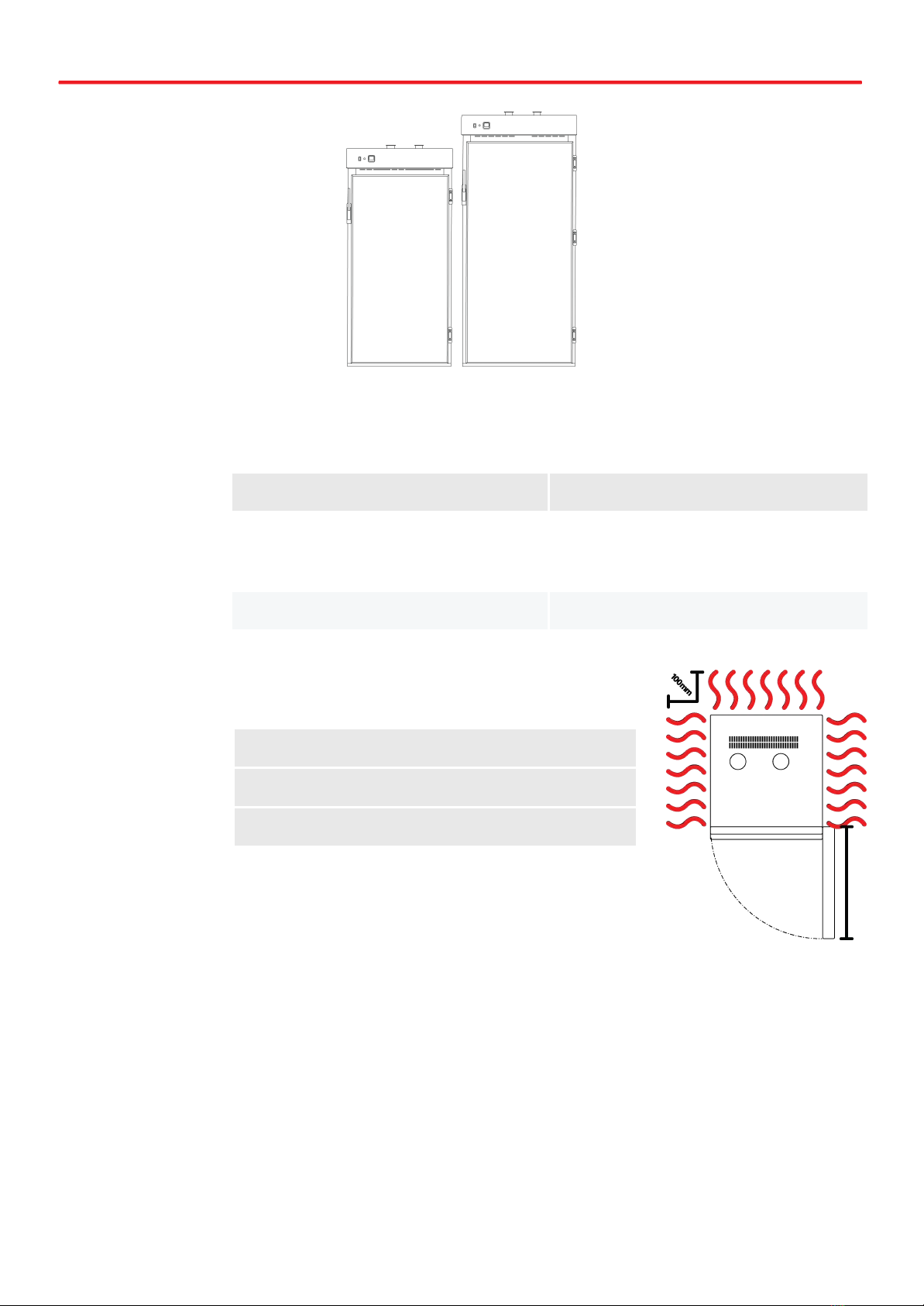
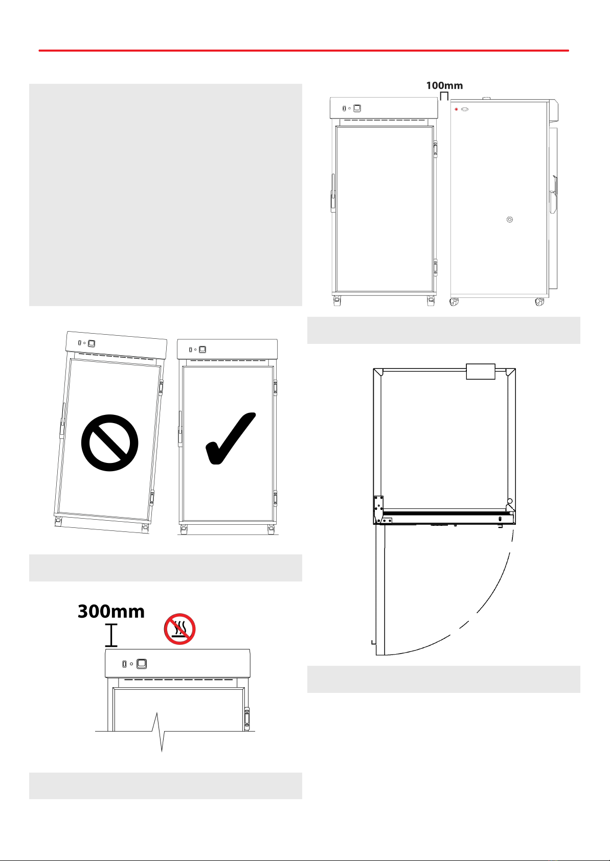
Clearance TD-80F TD-150F TD-250F TD-500F TD-700F TD-630F
Front (mm) 520 630 780 725
Back (mm) 100
Sides (mm) 100
5
Technical Specifications
Dimensions
External TD-500FM TD-700FM
WxDxH (mm) 780x810x1680 780x810x1980
Note: Inlet and Exhaust ports extend the overall height of the ovens by approximately 40mm.
Internal
WxDxH (mm) 650x650x1200 650x650x1500
Clearance TD-500FM TD-700FM
Front (mm) 780
Back (mm) 100
Sides (mm) 100
6

Technical Specifications
Technical
Specification
TD-80F TD-150F TD-250F TD-500F TD-700F TD-630F
Temperature
Range
Ambient +10°C to 200°C
Temperature
Control Stability
+/- 0.1°C
Temperature
Uniformity
+/-2°C @ 100°C +/-4°C @ 100°C
Heater Power 1500 watts 3000 watts
Electrical 7A/230V 13A/230V (requires 15A supply)
Nominal Capacity 80L 150L 250L 500L 700L 630L
Porthole
Diameter
13mm
Weight 60kg 100kg 110kg 170kg 190kg 190kg
Technical Specification TD-500FM TD-700FM
Temperature Range Ambient +10°C to 70°C
Temperature Control Stability +/- 0.1°C
Temperature Uniformity +/-2°C @ 70°C (unloaded and vents closed)
Heater Power 1500W
Electrical Requirement 10A/230V
Nominal Capacity 500L 700L
Porthole Diameter 13mm
Weight 170kg 190kg
7

Technical Specifications
Features TD-80F TD-150F TD-250F TD-500F TD-700F TD-630F
Shelves (max @100mm
spacing)
2 (max 3) 3 (max 4) 4 (max 6) 5 (max 9) 6 (max 11) 3 levels
(max 4)
Lockable Castors Optional
✔ ✔ ✔ ✔ ✔
Internal Fan
✔ ✔ ✔ ✔ ✔ ✔
Omron E5CC
✔ ✔ ✔ ✔ ✔ ✔
Solid Door
✔ ✔ ✔ ✔ ✔ ✔
Fibreglass Insulation
✔ ✔ ✔ ✔ ✔ ✔
Safety
Over Temperature
Safety
✔ ✔ ✔ ✔ ✔ ✔
Over Current Protection
✔ ✔ ✔ ✔ ✔ ✔
Options
BMS Plug No volt contact closure plug and socket connection to a Building Management System
Additional Shelves Additional Stainless Steel shelves to suit
Heavy Duty Shelves Update to allow for higher loads on shelves (limits total number of shelves possible for use)
Door Locks Key lockable door locks
Customisable Port Hole Add additional stainless steel 13mm port holes or choose 50mm port holes
Programmable
Controller (MSP)
(E5CC-MSP) Upgraded Omron Controller features 256 ramp and/or dwell segments
Glassware Drying See TGD-range for oven models specic to drying of laboratory glassware
Natural Convection See TO-range for oven models without fan forced circulation
8
Technical Specifications
Features TD-500FM TD-700FM
Shelves 10 12
Lockable Castors
✔ ✔
Internal Fan
✔ ✔
Omron E5CC-T
✔ ✔
Solid Door
✔ ✔
Fibreglass Insulation
✔ ✔
Safety
Over Temperature Safety
✔ ✔
Over Current Protection
✔ ✔
Options
BMS Plug No volt contact closure plug and socket connection to a Building Management System
Door Locks Key lockable door locks
Customisable Port Hole Add additional stainless steel 13mm port holes or choose 50mm port holes
The controller is preset with the following program using the Ormon E5CC-T
48 hrs. at 38˚C
48 hrs. at 45˚C
48 hrs. at 52˚C
“As per the Recommended Standards for Sampling Nut-In-Shell and Kernel Recovery Evaluation”
9

Operating Environment Drying Oven User Manual By Thermoline Scientific
Drying Oven Operating Environment Bench Top Location
Ensure that the drying oven is placed in the correct
environment, away from direct sunlight or direct heat sources
such as heaters (Fig 1). The product shouldn’t be placed in a
room where the ambient temperature exceeds that of which it
was designed to operate.
Drying ovens should be stored inside at all times. Failure to
adhere to this could cause signicant drops in cabinet
performance and damage to items stored inside.
Extreme Operating Environment:
• Temperature: 10°C to 32°C (+/-2.0°C)
• Humidy: Up to 85%RH
Optimal Environment: (Fig 2)
• Temperature: 23°C (+/-2.0°C)
• Humidy: 50%RH (+/-5%RH)
Fig 1. Suitable Environment
Bench Top Requirements:
• Under no circumstances should any ovens be stacked
on top of each other (Fig 2).
• Thermoline 150 litre ovens have removable castors for
benchtop storage. To safely remove castors, simply tip
the cabinet over gently onto it's back or side and
unscrew the castors from the bottom the cabinet (Fig
3). This is a two person job so please get assistance.
Fig 2.
Fig 3.
10

Operating Environment
Electrical Connections
Depending on the model the drying ovens either require a
require a 15amp, 230V, 50hz power supply or a 10amp 230V
50hz power supply. Requirements are shown in the below
table.
A dedicated outlet should be used for all ovens. Do not use
power boards or the like. A 3-pin moulded plug is supplied as
standard.
Electrical requirements
TD-80F
TD-150F
TD-500FM
TD-700FM
10A/230V
TD-500F
TD-630F
TD-700F
15A/230V
Electrical Conditions:
• All drying ovens include a 2.5m removable mains
power lead with a three pin plug and right angle female
IEC plug (straight plug for 15A). Ensure the product is
reasonably distanced from the power supply. (Fig 1)
• On the oven itself is a male IEC socket (Fig 2) and (Fig
3).
Fig 1. Suitable distance from power supply (2m)
Fig 2. 15amp IEC socket Fig 3. 10amp IEC socket
Fig 4. Location of of the IEC socket.
11

Operating Environment Warnings
Do not store items on top of the cabinet as this will also affect ventilation! CAUTION: When installing
more than one cabinet in the same location ensure that they are positioned in such a way that warm air
exhausted from one cabinet, is not drawn directly into the other cabinet.
Drying ovens should be stored inside at all times. Failure to adhere to this could cause signicant drops
in cabinet performance and damage to items stored inside.
Drying ovens are not suitable for use with ammable solvents! They are tted with components that may
be the source of ignition.
The drying ovens are designed for large capacity drying, and hot moist air will be discharged.
12

Setup Drying Oven User Manual By Thermoline Scientific
Unpacking
Unpacking process for foam wrapped or boxed
• The drying oven will be delivered foam wrapped and
on its castors via sensitive freight (Fig 1) or in a box on
a skid (Fig 2).
• If the drying oven is delivered on a skid, a forklift may
be required to lift it off the skid.
• Please don't dispose of the packaging until the oven is
inspected. If damage is present upon opening your
package, notify your supplier or Thermoline Scientic
without delay on +61 2 9604 3911 or email at
Fig 1. Unpacking Process (foam wrapped)
Fig 2. Unpacking Process (Box)
Moving
Moving the drying oven:
• Ensure that the oven is rolled on an even and at
surface. Uneven surfaces can cause the oven to fall
over.
NOTE: Drying ovens are 'Top Heavy'. Do not move the cabinet
too quickly. (Fig 3 & 4)
Fig 3. Safe moving of cabinet.
Fig 4.
13
Setup
Castors
The drying ovens are equipped with lockable castors to prevent
cabinet movement.
Castor Setup:
• Ensure that the drying oven is placed on an even and
at surface. Uneven surfaces can cause issues within
the cabinet. Uneven surfaces can cause the cabinet to
fall over or roll away with unlocked castors.
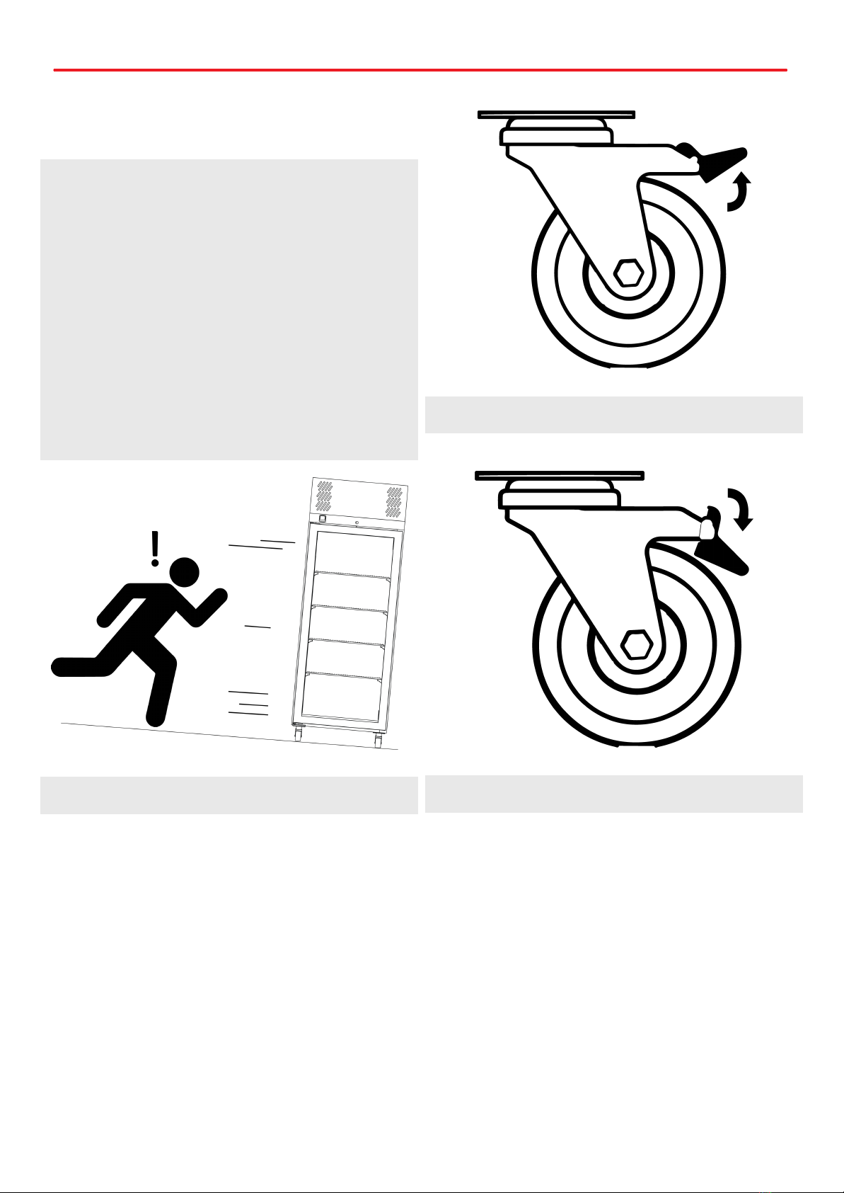
• Castors can be xed in place by pushing down on the
brake lever. Ensure the castors are locked to prevent
unwanted movement from the drying oven (Fig 1).
• Ensure when placing the drying oven into place that
the castors can be accessed so they can be locked
(Fig 3) and unlocked (Fig 2). Please contact your
supplier or Thermoline should there be any damage to
the castors.
Fig 1.
Fig 2. Castor Unlocked
Fig 3. Castor Locked
14
Setup
Drying Oven Location
Location Requirements:
• The drying oven requires a level surface to operate
correctly. (Fig 1)
• Do not store items on top of the drying oven (Fig 2).
Space is required to accommodate the inlet and outlet
vents.
• The drying oven requires ventilation. Thermoline still
suggests 100mm on the sides and back that also aids
with accessibility (Fig 3). 300mm at the top to ensure
the inlet and outlet vent is not obstructed in any way.
• The drying oven door should also be allowed to open
and close at full range. (Fig 4)
Fig 1. Correct Levelling
Fig 2.
Fig 3.
Fig 4.
15

Setup
Shelves
All ovens comes equipped with shelves used for holding items while the oven is in operation. They allow for more than one item to
be conditioned at a time. The shelves can be adjusted to different heights to accommodate different size items.
To adjust the shelf clips you must:
• Hook the top of the clip into the slot seen below.
• Pinch and squeeze the base of the clip
• Push base of clip into slot and release.
• To remove, repeat process.
SAFETY NOTE:
• The edges of the clips can be sharp. Thermoline
recommends using protective gloves while adjusting
or moving the clips (e.g. leather gloves).
Shelving:
• All ovens are supplied with adjustable shelf clips to
accommodate different size items within the cabinet,
The amount of shelf clips supplied changes depending
on the size of the cabinet ordered.
Model Shelvex Length (mm)
TD-80F 304
TD-150F 455
TD/-250F 455
TD-500F TD-500FM 915
TD-700F TD-700FM 1219
TD-630F 455
16

Setup
Inlet and Exhaust
All drying ovens feature an inlet and an exhaust port on top of
the cabinet. The inlet regulates the amount of fresh (dry air)
that enters the cabinet and the outlet regulates the amount of
exhaust air that can exit the cabinet. In combination, this
regulates the rate of drying.
Exhaust Requirements:
• The top covers of the inlet and exhaust can be rotated
either way to open up the exhaust and allow airow
(Fig 2). The air vents are located on the top of the
cabinet. (Fig 1)
• On all drying ovens covered in this manual the exhaust
is on the left and in the inlet is on the right as you look
at the oven. Due to the location and number of fans in
the different models the location may differ slightly,
but they are still in this conguration. (Fig 3).
• The drying oven's vents can also be connected to a
ventilation system whether it is exhaust only or both
inlet and exhaust. To do so, you must rst remove the
vent covers (Fig 4).
• To prevent a potential pressure drop, please ensure
that the pipe is no smaller than 75mm in diameter for
proper ventilation (Fig 4).
Fig 1.
Fig 2.
Fig 3.
Fig 4. Recommended minimum diameter 75mm
17
Setup
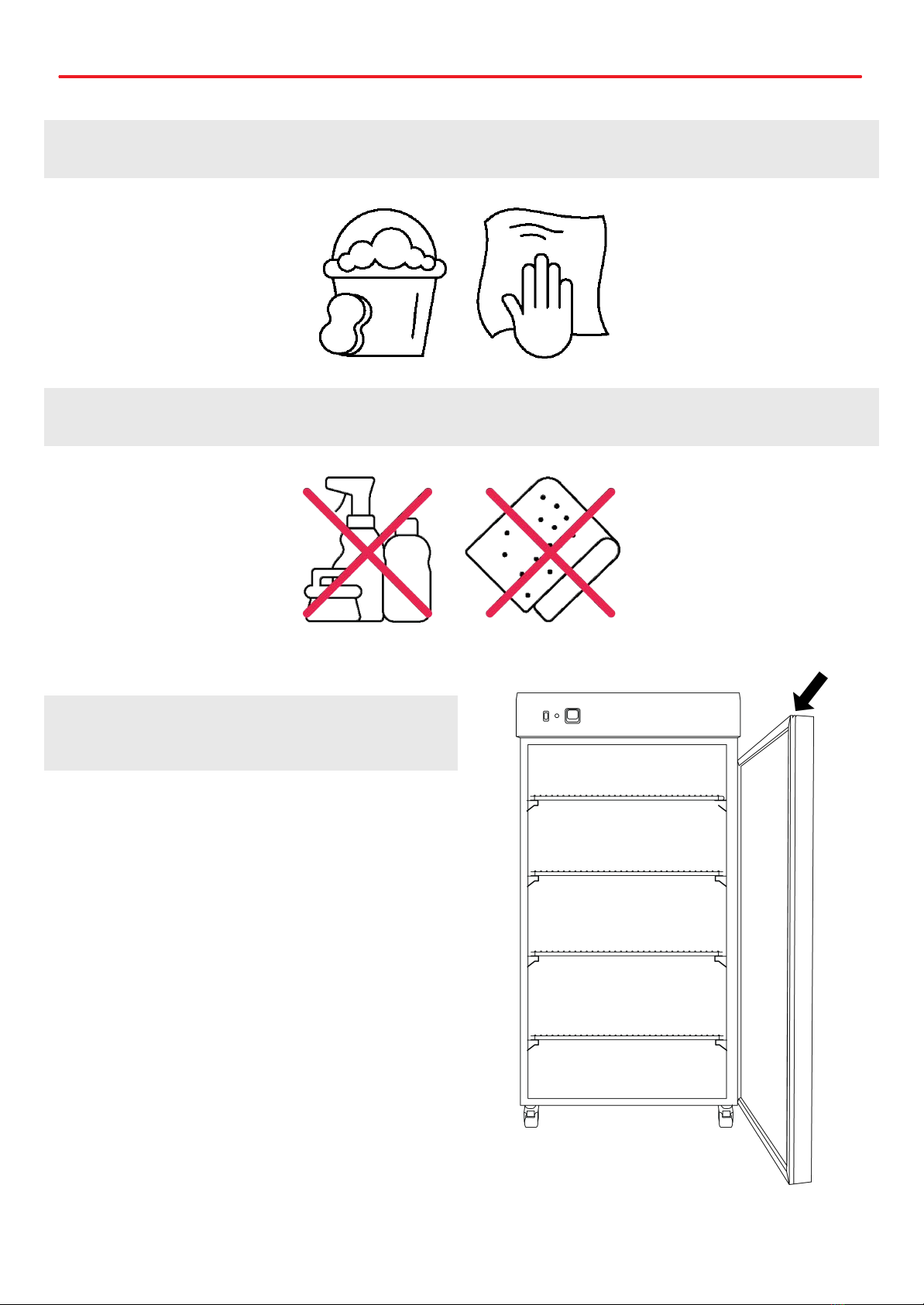
Cleaning
The interior, exterior, and door gasket can be cleaned as often as required using a soft cloth and soapy water. Never use abrasive
cleaners or scouring pads as these will scratch the surface and may result in corrosion. Never use caustic type cleaning agents.
All cabinets have electrical components. Power should be turned off prior to cleaning. These items should not be subjected to any
levels of moisture.
Door Gasket
The door gasket should be cleaned regularly with a mild soap
solution. If a gasket is to be replaced, please contact
Thermoline Scientic. Regular inspection is recommended.
18
Setup
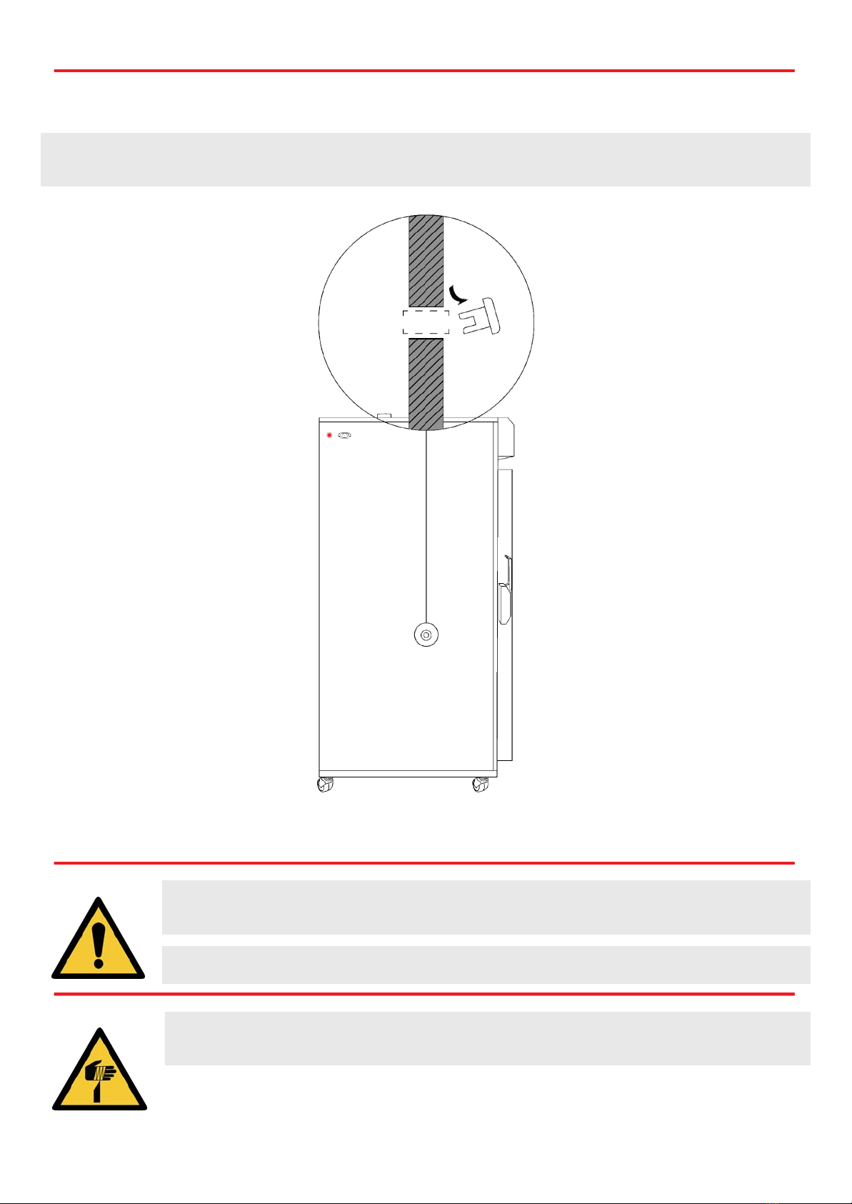
Port Hole
The port hole can be found on the left side of the drying oven. The cabinet comes equipped with a plug that may be removed by
simply pulling it out. Keep the plug safe in case the port hole needs to be closed again.
Setup Warnings
Ensure when placing the cabinet into place that the castors can be accessed so they can be locked and
unlocked. Any damage to the castors must be noted to the supplier or manufacturer
Ensure there are no blockages around or on top of the exhaust as this will effect proper ventilation.
Caution must be taken when removing the packaging particularly when using knives to cut tape and
cardboard.
19

Start Up Procedure Drying Oven User Manual By Thermoline Scientific
Start Up Procedure
Start Up process:
• Before proceeding, please make sure that all internal
and external packaging has been removed from the
appliance and that all tape, plastic bags and foam
pieces have been removed.
• Take the supplied lead and plug it into the male IEC
socket on the side of the oven. Next, plug the 3 pin
plug into a 10amp or 15amp General Purpose Outlet
depending on which is required.
• Turn the main switch adjacent to the temperature
control to 'ON' to start the Oven.
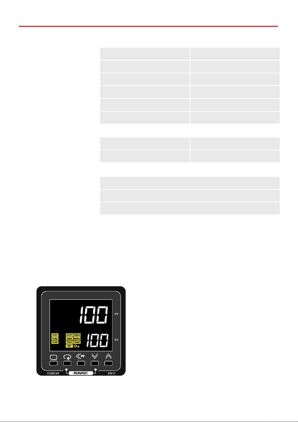
• The controller will go through a warm up period where
all segments of the display will be on, before indicating
the set temperature (SV) on the lower display and oven
actual temperature (PV) on the top display.
• For '-FM' models and those with the MSP option,
please see TM-009-UM Omron MSP manual for
instructions on this controller.
20
This manual suits for next models
9
Table of contents
Popular Oven manuals by other brands


Blomberg
Blomberg GGN61Z user manual

Middleby Marshall
Middleby Marshall PS640G Owner's operating and installation manual

Hotpoint Ariston
Hotpoint Ariston SA2540HWH Use and care guide

Atag
Atag OX4592C Instructions for use

Buffalo
Buffalo Y067 instruction manual

Electrolux
Electrolux air-o-convect Natural Gas Hybrid Convection Oven... Short form specification