Thermomax SM QUATTRO User manual

THERMOMAX
SM QUATTRO
4 - CHANNEL DATALOGGERANDALARM
ENGLISH
THERMOMAX
3
4
www.Thermomax-Group.com

CONTENTS
SECTION 1 - INTRODUCTION.................................................……..................... 2
SECTION 2 - INSTALLATION ............................................................….........……. 3
2.1 - SMQUATTROUnit ........................................................................... 4
2.2 - Sensors ............................................................................................. 4
2.3 - AlarmRelay ......................................................................…............. 5
2.4 - PowerConnections andWiringDiagram ..........................…...... 5
2.5 - Battery .....................................................................................….….. 5
SECTION 3 - OPERATION ..................................................................................…. 6
3.1 - DESCRIPTION ...........................................................................…... 6
3.2 - MAIN SCREENS:
3.2.1 MAIN SCREEN 1: Bar Graph Temperature / Humidity
Display ……........................................................................... 8
3.2.2 MAIN SCREEN 2: Digital Temperature / Humidity
Display .……….....................................…...………….......... 9
3.3 - SET SCREENS:
3.3.1 SETSCREEN 1:Clock/ Calendar ..................….............. 10
3.3.2 SETSCREEN 2:System Presets1 ...............................… 11
3.3.3 SET SCREEN 3: System Presets 2………………............ 13
3.3.4 SET SCREEN 4: Sensor Input Type Selection ……........ 14
3.4 - SYSTEM DIAGNOSTICS:
3.4.1 DATABANKDIAGNOSTICS SCREEN .........……….......... 15
3.4.2 CHANNELDIAGNOSTICS SCREEN ..............….............. 16
3.4.3 CALIBRATIONTRIMMINGSCREEN ................................. 17
3.5 - CHANNEL SCREENS: ……
3.5.1 CHANNELDISPLAY SCREENS ........................................ 18
3.5.2 CHANNELSETSCREEN - TEMPERATURE ..……........ 19
3.5.3 CHANNELSETSCREEN – HUMIDITY ………....……... 20
3.6 - CURRENT DAY PLOT: ………………………................……. 21
3.7 - PLOT HISTORY: Data log of previous days: ...................…... 22
3.8 - DATATRANSFER: ….................................…..................….….. 24
3.8.1 Transferring Data Using the Masterlink software ......... 24
3.8.2 Transferring Data to the Masterlink Hardware .............. 24
3.8.3 Printing Data to the Thermomax Serial Printer ............. 26
3.9 - DATATRANSFER -Panelmountunits Only ................................ 27
SECTION 4 - FAULTFINDING …........................................................................... 31
SECTION 5 - SPECIFICATIONS …..................................................…….............. 32
KEYPADLOCK …………………………………………………..………............… 33
SMQUATTROPANELMOUNT ............................................................................... 34
DEUTSCHE BEDIENUNGSANLEITUNG …………………………………....... 36
1

SECTION 1 INTRODUCTION
The SM QUATTRO microprocessor-based datalogger uses the novel approach of a
paperless logging and filing system, which allows the data of any day in its history to
be read and examined with a few key presses.
The large graphics LCD display communicates the information to the user with clarity,
making programming and setting up friendly and uncomplicated, without
compromising its sophistication and digital accuracy.
SUMMARYOFFEATURES
DATALOGGER
•Paperless datalogger with automatic filing by date
•50-year clock/calendar for datalogger filing.
•The temperature from each Channel is sampled every 15 minutes and stored
to an internal databank.
•‘Percentage of internal databank used’ indication in bargraph and digital form.
•Power Supply 220 – 240V AC Mains.
•Contents of internal databank can be transferred directly to the PC using the
MASTERLINK Software or via a MASTERLINK Hardware module to a PC at a
remote site.
ALARM
•2-Stage high and low level alarms with mute and reset facilities,
•Stage 1 temperature threshold with trigger delay.
•Stage 2 limit temperature with immediate trigger.
•Status window for system fault indication.
•Diagnostics screen revealing system parameters.
•Alarm history record for low alarm, high alarm and power fail.
•Battery back-up for power-fail operation.
Note: The information supplied in this manual is for guidance only – no part of this
may be used for any agreement, whether express or implied, or to form any contract.
2

SECTION 2 INSTALLATION
Note: This installation procedure is for guidance only, and its suitability
should be verified by the installer.
SAFETY PRECAUTIONS
The following safety precautions are strongly recommended:
1Before attempting to install and operate the unit, read this instruction manual
carefully.
2Installation and any maintenance required should only be carried out by
suitably qualified personnel.
3It is recommended that the unit be connected to the mains supply via a
suitably rated isolating switch.
4WARNING: When the unit is connected to the mains supply and the
cover is opened, the circuits at mains voltage will be exposed. Therefore
when installing the unit, ensure all required connections (including battery
connection, if included), are made and covers replaced before turning on the
mains supply. Ensure that all the connections made are secure. If any
maintenance work e.g. installing a new battery, is required ensure that the
unit is isolated from the mains supply before removing the cover. Never
leave the unit unattended if the cover has been removed and the mains
supply is connected.
5Do not exceed unit ratings as shown on the ratings label.
6It is advisable to route mains cables away from low voltage or sensor cables.
3
2.1 SMQUATTRO UNIT
NOTE: For viewing comfort, the SM QUATTRO unit should be positioned at
eye level. It is always good practice to keep electronic equipment away from
cold, heat and electrical plant, as extremes of temperature may reduce the
lifetime of the device, and heavy electrical loads, switches, relays or
contactors too close to the device may cause electrical and electro-magnetic
interference when switched on or off.
2.1.1 Knock out the entries into the moulding to be used for connection, either
behind or under the moulding, whichever is suitable for the particular
installation.
2.1.2 Fasten the screw corresponding to the top centre lug on the back of the SM
QUATTRO moulding, into the wall or panel on which the unit is to be
mounted. Leave a gap of approximately 3mm between the screw head and
the wall. Position the moulding and slot in the lug over the screw.
2.1.3 Level the SM QUATTRO moulding and, if using rear entry, mark the entry
holes in the panel behind the appropriate knock-out entries, as well as the
two lower mounting holes. Remove the moulding, drill the necessary holes in
the panel, assemble any grommets or conduit adapters if used, replace the
moulding and fasten using the two lower screws.
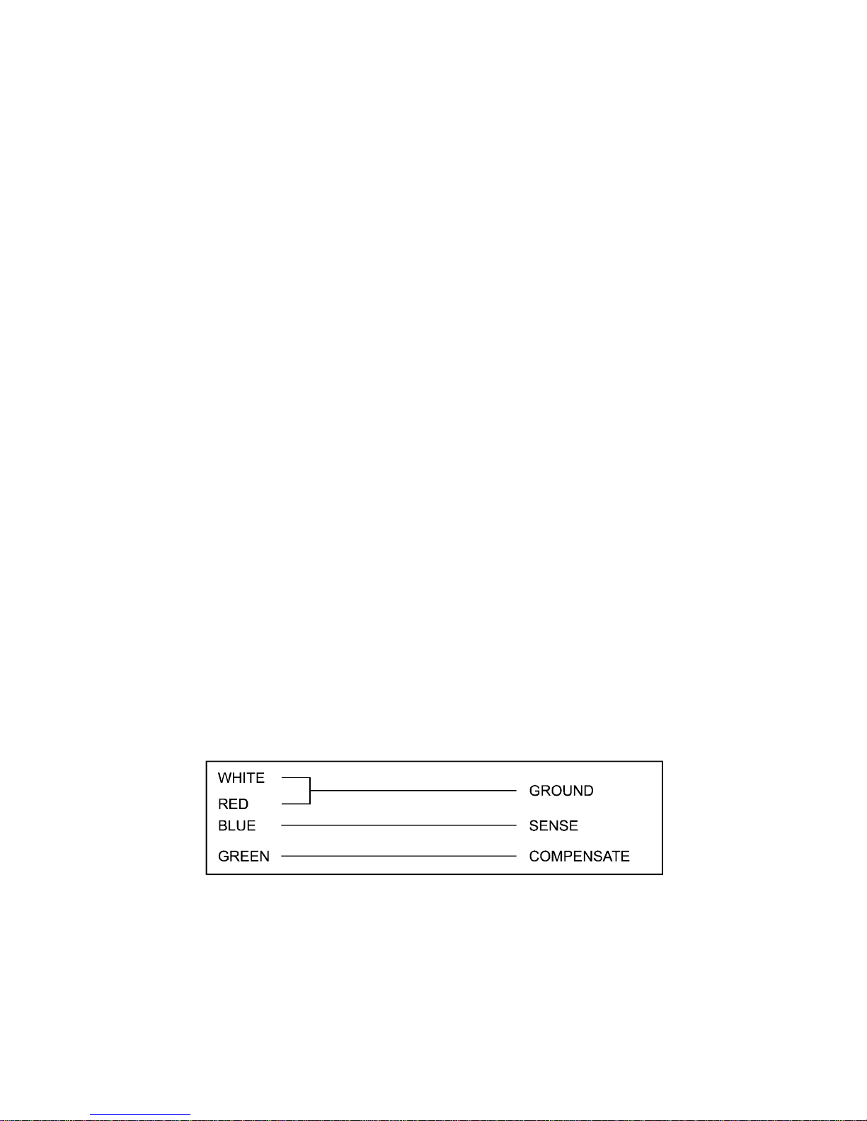
2.2 SENSORS
The SM QUATTRO may be used with a variety of sensors of different cable
lengths. If required, sensors are available with extended cable lengths or
alternatively, sensor extenders are available, also in a variety of lengths. If the
sensors need to be extended, but factory-made extenders are not available,
they can be extended using a suitable 4 core or 3 core cable, according to
the diagram shown below.
Please note however, that as with all PT100 sensor applications, a good
connection is vital. It is therefore recommended that wherever there is any
doubt, a factory- extended sensor or sensor extender should be used.
4
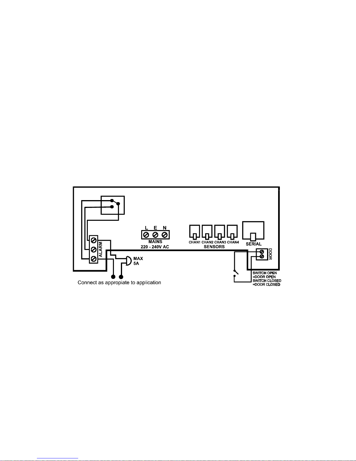
2.3 ALARMRELAY
NOTE: The alarm relay is a 3 contact changeover arrangement which is
isolated (volt-free). This relay is normally energised, and switches off when
the alarm is triggered, or in the case of power failure. It may be used to
trigger an external bell, warning lamp, or digital communicator (telephone
dialler).
If an external device is used, connect the alarm as appropriate, according to
the diagram in the next section.
2.4 POWERCONNECTIONSAND WIRING DIAGRAM
NOTE: This device should be properly earthed. Flexible wires simplify
connection to the terminals. All connections should be secure and adequately
tightened. It is good practice to keep mains cables away from sensor cables
and other low voltage signal cables.
Connect the supply to the unit, as per diagram below, using the appropriate
input voltage according to the application.
2.5 BATTERY
The battery supplied is a 9V PP3 nickel metal hydride rechargeable battery
and is attached to the lid of the terminal compartment, but not plugged in.
This should be plugged in after installation. This battery is not essential for
the system operation, but is used in the case of power failure, thereby
continuing to log the four input temperatures for 3 – 4 hours, and maintaining
the system clock.
If the power cut takes longer and the battery is discharged, the clock must
be set when the power supply is re-established. The system parameters
remain intact.
It is recommended that the battery is changed every 12 months, in order to
maintain good power failure operation. When replacing, ensure that the type
of battery used is as specified.
5
SECTION 3 SM QUATTRO OPERATION
In order to fully understand the operation of the SM QUATTRO, this section should
be read carefully.
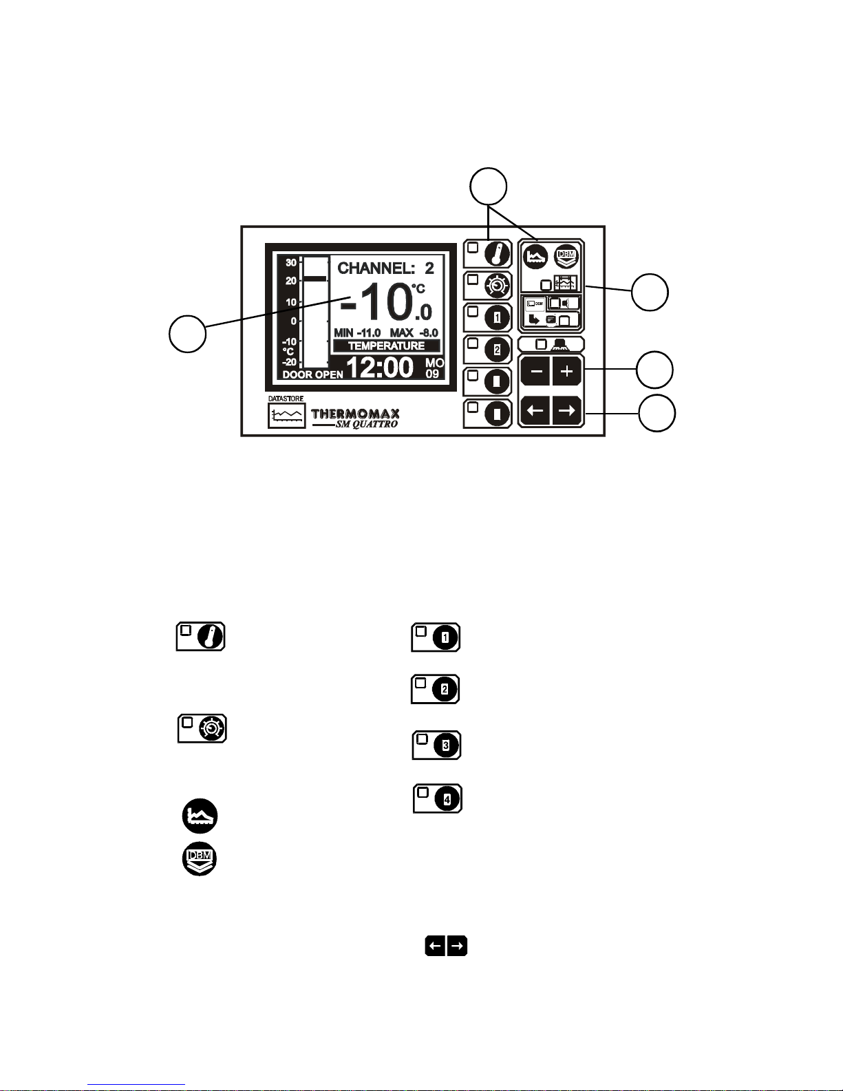
3.1 DESCRIPTION
THERMOMAX
3
4
1GRAPHICSLCDDISPLAY
Displays all the information. The contrast is adjustable to suit the user. (See
3.2.1 Main Screen 1).
2FUNCTION KEYS
There are eight function keys on the SM QUATTRO datalogger:
- Main Screen 1 - Channel 1 Display Screen
- Main Screen 2 - Channel 1 Set Screen
- Channel 2 Display Screen
- Channel 2 Set Screen
- Set Screen 1
- Set Screen 2 - Channel 3 Display Screen
- Set Screen 3 - Channel 3 Set Screen
- Set Screen 4 - Channel 4 Display Screen
- Current Day Plot - Channel 4 Set Screen
- Plot History Screen
- Data Transfer Key
3SELECT KEYS
Within each function, there are some parameters that can be selected for
setting or displaying purposes. The keys allow the required parameter
to be chosen, without changing any of its properties.
6
4
2
1
5
3

7
4SET KEYS
The and keys are used to set the value of any selected parameter, by
increasing and decreasing the value respectively.
In most of the functions, described later in the manual, the and keys
have an auto-repeat facility: press and hold the key in order to advance
quickly.
Note: The and keys are the only keys which can alter the value of a
selected parameter. Other keys may be pressed to view or select these
parameters without effecting any change in the system.
5INDICATORS
The System Alarm can be triggered by the high temperature alarm, low
temperature alarm, or by a sensor fault.
INTERNAL DATABANK
DATA TRANSFER IN PROGRESS
SYSTEM ALARM
8
3.2 MAINSCREENS
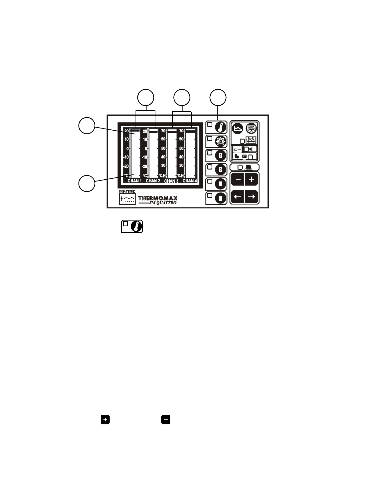
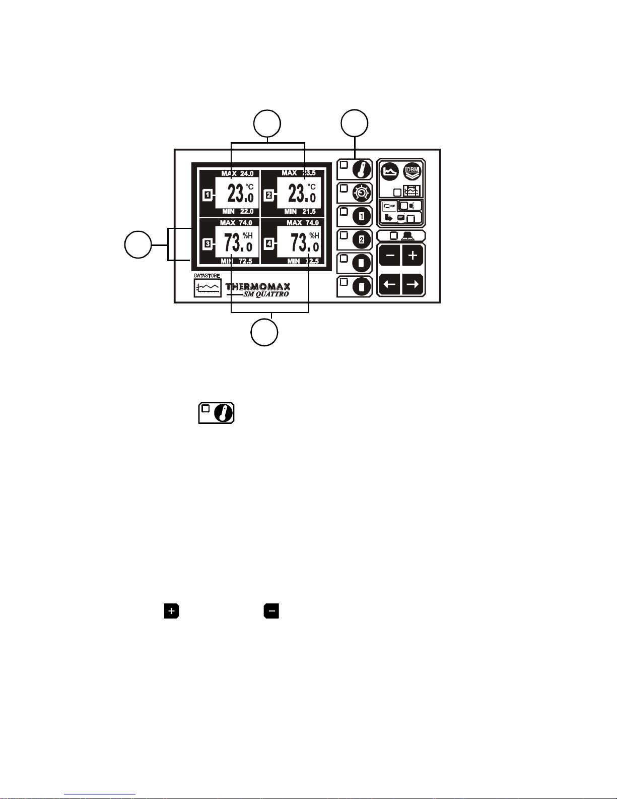
3.2.1 MAIN SCREEN 1: BAR GRAPH TEMPERATURE / HUMIDITY DISPLAY
This screen allows the user to view the information for each channel in
bargraph form and is shown below. The high and low Temperature / Humidity
limits are shown on these bargraphs and are represented by the shaded
areas.
THERMOMAX
3
4
Pressing the key the first time will display the MAIN SCREEN which
shows a four channel bargraph display as shown above.
2Channels 1 & 2 in this example display temperature.
3Channels 3 & 4 display relative humidity in this example.
4This shaded area shows the High Alarm Limits (Stage 2 Alarm).
5This shaded area shows the Low Alarm Limits (Stage 2 Alarm).
Note 1:
In this example configuration, channels 1 & 2 are connected to temperature
sensors and channels 3 & 4 are connected to humidity sensors, therefore the
bargraph for channels 3 & 4 displays relative humidty (%H). (See section
3.3.4).
Note 2:
See Section 3.5.2 “Channel Set Screens” for more information on
temperature Alarms, and section 3.5.3 for information on Humidity Alarms.
Note 3:
The display contrast may be adjusted in this screen.
Press to increase and to decrease the contrast.
To adjust quickly, press and hold for auto-repeat.
4
5
231
9
3.2.2 MAINSCREEN2:DIGITALTEMPERATURE/HUMIDITYDISPLAY
1MAIN SCREEN function selector.
Pressing the key a second time reveals the screen above.
2Current temperature for channels 1 & 2.
3Current humidity reading for channels 3 & 4.
4Maximum and minimum daily temperature / humidity readings for each
channel.
Note: The display contrast may be adjusted in this screen.
Press to increase and to decrease the contrast.
To adjust quickly, press and hold for auto-repeat.
4
3
21
10
3.3 SETSCREENS
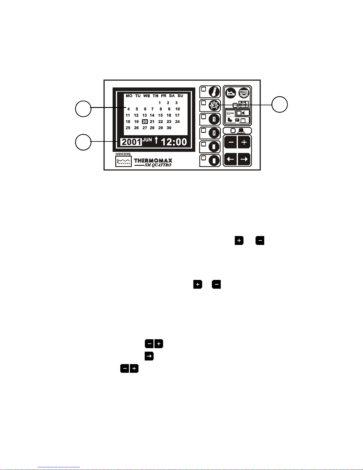
3.3.1 SET SCREEN 1 : CLOCK / CALENDAR
THERMOMAX
3
4
1SET SCREEN function selector
The datalogging system uses the calendar to file the logged data.
2Selection indicator
The highlighted parameter is adjusted by pressing the or key..
(The selections are: ‘year’, ‘month’, ‘day’, ‘↑’, ‘hour’ and ‘minutes’.)
The ‘↑’ indicates that the day on the calendar above is being set.
The clock is in 24-hour format.
To advance quickly, press and hold the or key for auto repeat.
3Calendar
This is the calendar of the month selected, with day of the week indication.
SETTINGTHEDATEANDTIME:
Step 1 : Use the keys to set the current ‘Year’.
Step 2: Use the key to move to the ‘Month’ option and then use the
keys to set the current month.
Step 3: Repeat step 2 to set the current ‘date’ and ‘time’ (‘minutes’
and ‘hours’) in turn.
2
31

11
3.3.2 SETSCREEN2:SYSTEM PRESETS 1
THERMOMAX
3
4
1SET SCREEN function selector
Pressing this key a second time reveals Set Screen 2.
2Alarm Mute
To mute the SM QUATTRO’s internal audible alarm, press the key when
the MUTE window is selected. When the alarm system is reset, either
manually or by the temperatures dropping within pre-set limits, the alarm
mute will be cancelled automatically.
3Alarm Reset
Any current activities, delays or counters are reset by pressing the key
when the RESET window is selected.
4Alarm Relay Status
The output status of the alarm relay may be either viewed or altered by
pressing the or key when the RELAY window is selected.
0 = Relay Manually disabled (ALARM ON)
AUTO = For normal operation:
1= Relay Manually activated (ALARM OFF)
6 7 8 9
2 3 4 5
1

12
5Keypad Lock
The keypad may be locked or unlocked when this window is selected.
See page 27 at the end of this manual.
6Piezo and Indicator test
By pressing the key when the TEST window is selected, the SM
QUATTRO’s internal audible alarm will ‘sound’ and all indicators will
illuminate.
7Door Switch Selection
The SM QUATTRO provides the option to connect a door switch for
monitoring purposes (the status of the door is displayed and logged in
graphical form, see section 3.6). This option may be enabled or disabled by
pressing the or respectively..
Note: See section 2.4 for wiring diagram.
8Diagnostics
By pressing the key when the DIAG window is selected, the SM
QUATTRO DIAGNOSTICS screen is activated. (see next section 3.4).
9Language Selection
The language used by the system to communicate the information may be
selected here. Use the and keys to make your English, French or
German selection.

13
3.3.3 SETSCREEN3:SYSTEM PRESETS 2
THERMOMAX
3
4
1SET SCREEN function selector
Pressing this key a third time reveals Set Screen 3.
2Alarm Mute
Alarm mute period for Channel 1 (from 0 to 95 Minutes). If any key is
pressed during an Alarm situation for this channel, the buzzer will be muted
(silenced) for this period.
3-5 Alarm Mute period for Channel 2 to Channel 4(from 0 to 95 Minutes).
Same as above.
6Channel select for Channel 1. Each sensor input can be “switched” on or off
by pressing the or keys for 5 seconds respectively. When the sensor
input is switched “ON”, the unit will operate in normal mode and the actual
sensor temperature will be monitored and logged to the databank every 15
minutes. If the sensor input is switched “OFF”, the unit will display 0°C
continuously. This value will also be logged to the databank. Hence it is
therefore only necessary to connect sensors to the required number of
inputs.
Note: If a channel is switched off, the Alarm parameters will automatically
revert back to the default factory settings to prevent an alarm occurrence.
These parameters cannot be changed until the sensor input is switched on
again.
7-9 Channel Select for channel 2 to channel 4.
6 7 8 9
2 3 4 5
1

14
3.3.4 SETSCREEN4:SENSORINPUT TYPE SELECTION
The new SM Quattro now has the ability to measure, display and record
Relative Humidity (as a percentage %H) on any of its 4 sensor inputs using
the Thermomax Humidity Sensor (CO429). The 4 sensor inputs can be
configured to read either Temperature or Relative Humidity. As a factory
default, all 4 sensor inputs are configured to accept temperature sensors.
The following paragraph describes how to change the configuration for each
sensor input if required.
1In order to change the sensor input configuration, press the key four
times to reveal the new INPUT SELECTION screen as displayed below. This
screen gives you the option to choose the sensor type to be used with each
of the four input channels. This can be either the standard PT100
temperature sensor or the Humidity Sensor.
THERMOMAX
3
4
2By using the keys, you can move to the required channel
selection window.
3Pressing the key, allows you to select the input channel for
connection with a humidity sensor for measurement of relative humidity
percentage.
4Pressing the key selects an input for connection with a standard
PT100 temperature sensor.
For example, the diagram above shows channels 1 and 2 configured as
Temperature inputs and 3 and 4 configured as Humidity inputs.
Note: The information displayed on various screens will vary,
depending on the sensor type input as selected above (humidity /
temperature).
15
3.4 SYSTEM DIAGNOSTICS
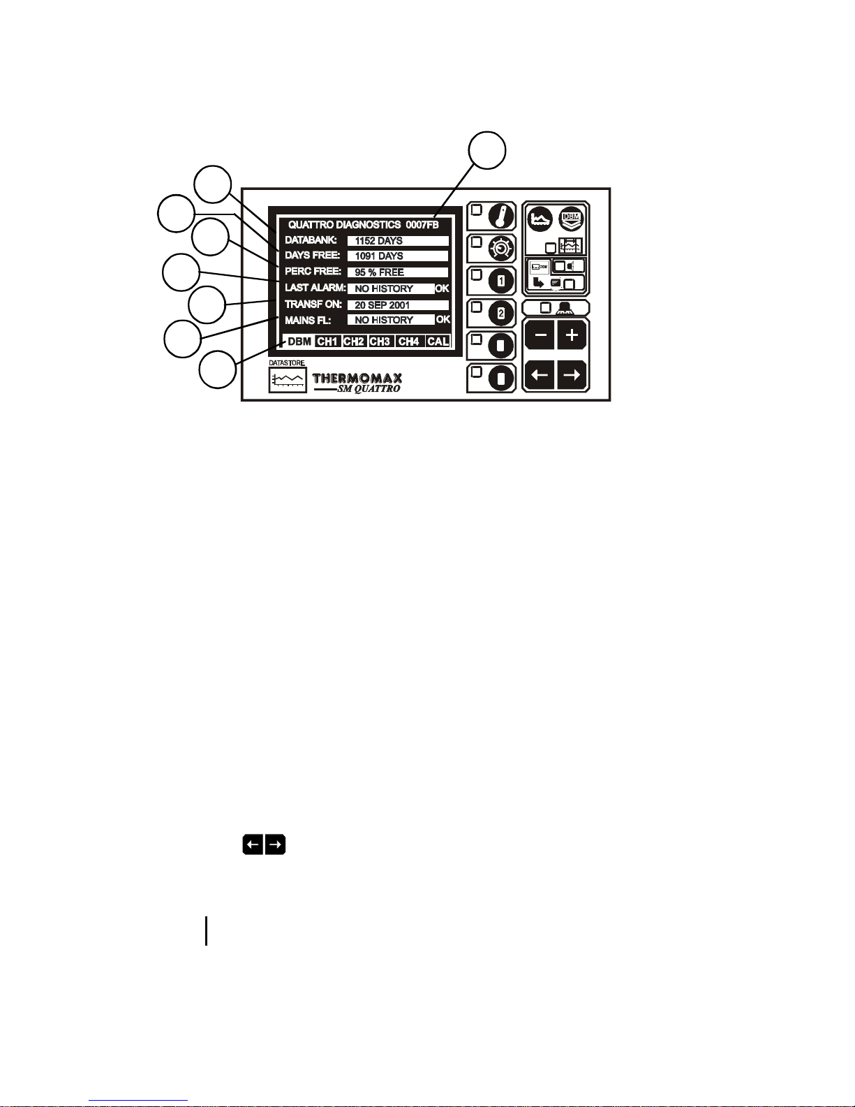
3.4.1 DATABANK DIAGNOSTICS SCREEN
THERMOMAX
3
4
1This is the unique electronic signature of the SM QUATTRO.
2The DATABANK window shows the capacity of the internal databank.
3The DAYS FREE window shows the number of days which have not yet been
used.
4The PERC FREE window shows the percentage of the databank which has
yet not been used.
5The LAST ALRM window shows the last date on which an alarm condition
occurred.
6The TRANSF ON window shows the date on which the contents of the
internal databank need to be transferred.
7The MAINS FL window shows the last date on which the powerfailed. During
a power fail situation this window will display the duration, in minutes, of the
power failure.
8Diagnostics Screen Selection.
Use the keys to move between one of four diagnostic screens:
-DBM : Databank Diagnostics Screen (Ref. 3.4.1 above)
- CH1 : Channel 1 Diagnostics Screen (Ref. 3.4.2)
- CH4 : Channel 4 Diagnostics Screen (Ref. 3.4.2)
- CAL : Calibration Trimming Screen (Ref. 3.4.3)
8
1
7
6
5
4
3
2

16
3.4.2 CHANNELDIAGNOSTICSSCREEN
THERMOMAX
3
4
1The CHANNEL window shows the number of the currently selected channel.
2The INPUT TYPE window shows which type of sensor is being used. (PT100
in this case – this is the only type used by the SM QUATTRO at present).
3The CALIB DATA window shows calibration values, for factory use only, and
the current temperature reading.
4The LAST CALIB window shows the date when the SM QUATTRO was
calibrated.
5The AL HIGH window shows the date when the last high alarm condition
occurred for this channel.
6The AL LOW window shows the date when the last low alarm condition
occurred for this channel.
1
2
3
4
5
6

17
3.4.3 CALIBRATIONTRIMMINGSCREEN
Calibration trimming allows qualified personnel to adjust the SM
QUATTRO’s calibration by ±2oC.
Note: A known reference temperature should be used.
THERMOMAX
3
4
To enter the CALIBRATION TRIMMING Screen, press and hold the key
for 5 seconds.
THERMOMAX
3
4
Use the keys to move to the channel which requires calibration
trimming. Then use the or keys to adjust the current temperature
reading.
Current
Readings
3.5 CHANNELSCREENS
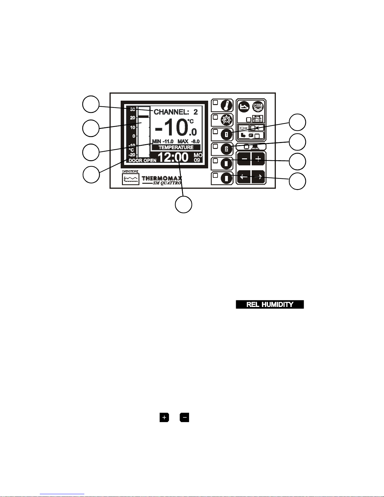
3.5.1 CHANNELDISPLAY SCREENS
THERMOMAX
3
4
1 to 4 CHANNEL 1 to 4 function selector
Pressing any key of these keys a second time will display the “Channel Set
Screen” for that channel.
5Clock display : 24-hour format with day of week abbreviation.
6Temperature bargraph : High and low alarm limits are shown as
shaded areas.
7If any channel has been set up to read humidity, will
be displayed in this area, and all values will be displayed as % relative
humidity.
8Digital display of Channel temperature / humidity, with minimum / maximum
indication. The minimum and maximum values are daily values, and are
reset at midnight.
9When the door switch facility is activated (see 3.3.2) this area will show the
status as ‘door open’ or ‘door closed’. Note that if there is no switch
connected, the unit will display ‘door open’.
Note: The display contrast may also be adjusted from any of these
screens by pressing the or keys.
18
8
5
6
7
94
3
2
1

19
3.5.2 CHANNELSET SCREENS–TEMPERATURE
THERMOMAX
3
4
1 to 4 Channel 1 to 4 function selector
Pressing any of these keys a second time will display the “Channel Set
Screen” for that channel.
5 Bargraph Display Scale
By pressing the or key, the bargraph display scale may be adjusted to
show the temperature range best suited to the particular installation. This
scale is also used for the “Plot display” (Ref. 3.6 Current Day Plot and 3.7
Plot History).
6 High Alarm Stage 1 temperature (-50°C to +50°C)
The Stage 1 alarm is a time / temperature related alarm. If the
maximum threshold is exceeded, a timer is initiated, and no further action is
taken at this time.
7 High Alarm Stage 1 Delay (1 – 99 min.)
After the maximum threshold has been exceeded (Ref. 4 above), the alarm
will not be triggered until the timer exceeds the time delay set here. If the
temperature drops below the threshold before the expiry of this delay, the
timer is reset. If following this the temperature rises above the threshold
again, the timer restarts from zero.
8 High Alarm Limit Stage 2 temperature (-50°C to +50°C)
If at any time this limit is exceeded the time delays will be overridden and the
alarm will trigger immediately.
9 Low Alarm
All the functions described in 6-8 above also apply to the low alarm.
76 8
5
9
4
3
2
1
Table of contents
Other Thermomax Data Logger manuals


