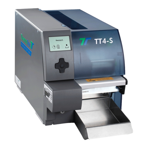
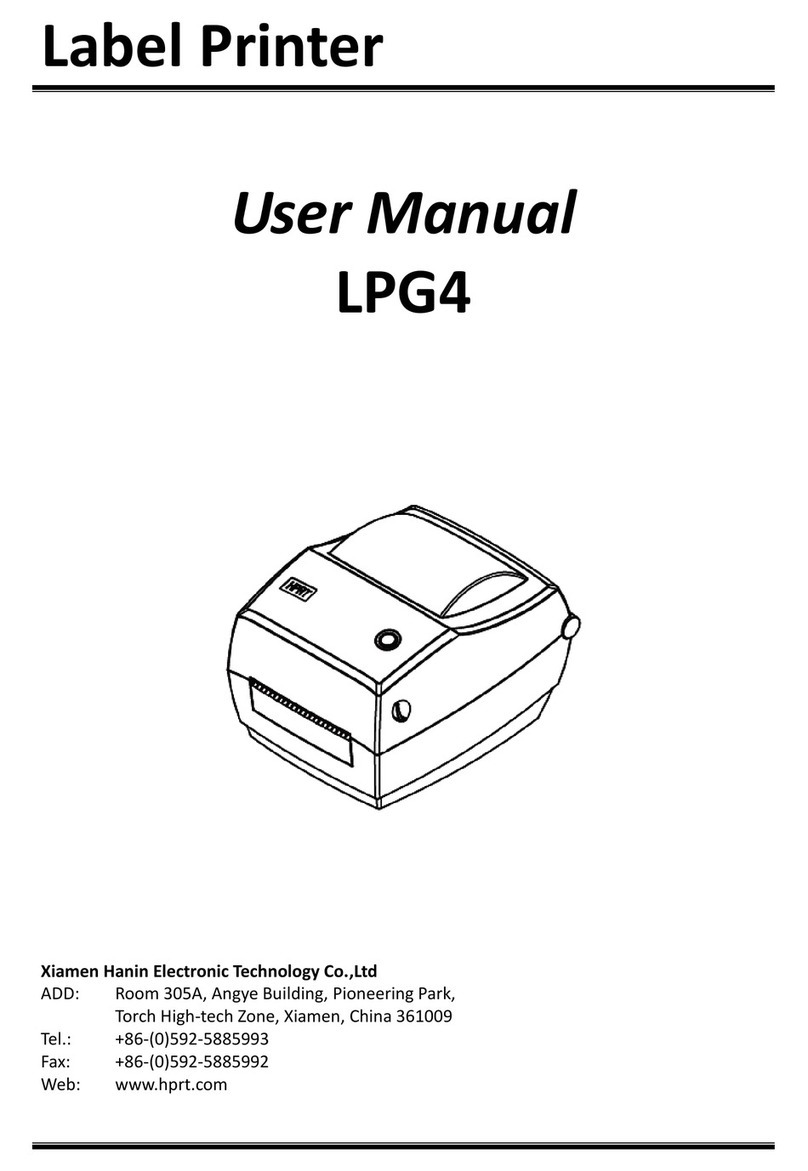
ThermoTex TT3-L User manual

ThermoTex Nagel GmbH
Schutterstraße 14, D-77746 Schutterwald
Tel.: +49 (0)781/9616-0, Fax: +49 (0)781/9616-50
info@thermo-tex.de, www.thermo-tex.de
GBTT3LBA.003
Operating manual for
TT3-L
- Translated version of the original operating manual -

Contents
GBTT3LBA_V(3).DOC Page - 2
Contents
1Product description ..........................................................................................................3
1.1 General........................................................................................................................................................ 3
1.2 Scope of supply ........................................................................................................................................... 3
1.3 Parts of the printer ....................................................................................................................................... 3
1.4 Properties of the thermo print head ............................................................................................................. 6
1.5 Technical data ............................................................................................................................................. 6
1.6 Declaration of conformity............................................................................................................................. 7
2Safety instructions............................................................................................................8
2.1 Warning symbols ......................................................................................................................................... 8
2.2 Hazard zones on the machine..................................................................................................................... 8
2.3 Duty of care of the machine owner.............................................................................................................. 8
2.4 Essential safety measures during normal operation.................................................................................... 9
2.5 Fundamental safety measures during maintenance and service ................................................................ 9
3Initial commissioning .....................................................................................................10
3.1 Power connection ...................................................................................................................................... 10
3.2 Connecting to the computer ...................................................................................................................... 10
3.3 Inserting labels .......................................................................................................................................... 10
3.4 Inserting the ink ribbon .............................................................................................................................. 11
3.5 Adjusting the label thickness ..................................................................................................................... 13
3.6 Adjusting the tape width ............................................................................................................................ 13
3.7 Adjusting the ink ribbon tension................................................................................................................. 14
4Operation .........................................................................................................................15
4.1 Control panel ............................................................................................................................................. 15
4.2 Normal operating mode ............................................................................................................................. 15
4.3 Printer set-up mode ................................................................................................................................... 16
4.4 Self-test mode ........................................................................................................................................... 17
4.5 Hex dump mode ........................................................................................................................................ 17
4.6 Adjusting the printing method .................................................................................................................... 17
4.7 Sensor setting............................................................................................................................................ 17
5Troubleshooting..............................................................................................................19
5.1 Fault messages ......................................................................................................................................... 19
5.2 Troubleshooting when printing .................................................................................................................. 20
6Cleaning...........................................................................................................................21
6.1 General cleaning ....................................................................................................................................... 21
6.2 Cleaning the printing roller......................................................................................................................... 21
6.3 Cleaning the print head ............................................................................................................................. 21
6.4 Cleaning the cutting device ....................................................................................................................... 22
7Spare parts list ................................................................................................................22

Product description
GBTT3LBA_V(3).DOC Page - 3
1 Product description
1.1 General
TT3-L is a label printer for both thermotransfer printing and also for thermo direct printing, and offers great
variability in the printing image design.
Thermotransfer printing requires a special ink ribbon together with the label material. The printing image is
produced by heating dots on the ink ribbon with corresponding transfer of the ink particles to the label.
Thermo direct printing is based on using label material with a thermoreactive coating. The printing image is
created by heating dots of the material at the thermo print head, causing corresponding changes in colour to the
coating.
The unit must only be used for printing labels, continuous paper and similar materials.
Safe operation of the machine cannot be guaranteed if the TT3-L is not used for its
intended purpose.
Compliance with all information in the operating manual is an integral part of proper use.
1.2 Scope of supply
The standard scope of supply includes
•thermotransfer printer TT3-S (with/without cutting device)
•roller holder, roller core
•operating manual
•power lead
•printer lead
•cleaning set
•WinTexx CD (including Windows printer driver)
•empty paper core for the ink ribbon winder
1.3 Parts of the printer
Fig. 1-1 -Parts of the printer
1
4
2
3
5

Product description
GBTT3LBA_V(3).DOC Page - 4
1 Housing
2 Air slits
3 Control panel
4 Window for checking consumed material
5 Window for checking consumed material
Fig. 1-2 -Parts of the printer
1 Switch for the direction of rotation of the ink ribbon winder. Must be at the bottom for ink ribbons
with the ink on the outside.
2 Drive for the ink ribbon winder
3 Push button for closing the print head
4 Ink ribbon holder
5 Front cover, is removed to fit the cutter
Fig. 1-3 -Parts of the printer
1 Front button for adjusting the ink ribbon tension
2 Front button for adjusting the ink ribbon
3 Wheel for adjusting the width of the label material
4 Rear button for adjusting the ink ribbon tension
5 Rear button for adjusting the ink ribbon
6 Wheel for adjusting the thickness of the label material
7 Lever for opening the print head
3
2
1
5
4
6
7

Product description
GBTT3LBA_V(3).DOC Page - 5
Fig. 1-4 -Parts of the printer
1 Print head
2 Sensor arm
3-1 Upper sensor
3-2 Lower sensor
4-1 Left guide for the label material (fixed)
4-2 Right guide for the label material (adjustable to the width)
5 Transport roller
6 Cover for the cutter connecting plug
7 Guide for the label roll
8 Holder for the label roll
F
In addition, the external roll holder with roll core for backing tape rolls can be
inserted with an inner diameter of 76 mm.
Connections
Fig. 1-5 -Connections
3-2
3-1
1
2
5
4-2
6
4-1
7
8
2
3
1
4
5

Product description
GBTT3LBA_V(3).DOC Page - 6
1 Serial interface RS-232C
2 Parallel interface (IEEE1284)
3 USB interface (USB)
4 Power switch
5 Power plug
1.4 Properties of the thermo print head
Caution!
The thermo print head is the most delicate part of your printer. Please always
comply with the following instructions.
1. Do not touch the glass safeguard on the print head with your hand. Do not use any sharp objects (knife,
screwdriver, etc.) to clean the print head.
2. During printing, make sure that there are no impurities on the label which could be pulled through under the
print head. These could damage the head.
3. Ensure the label has a good, smooth surface. Rough label surfaces act as sandpaper and reduce the service
life of the head.
4. Clean the head regularly with cotton buds soaked in alcohol.
5. Print at the lowest possible head temperature.
Incorrect handling can damage your print head very quickly.
1.5 Technical data
Electrical data
Operating voltage: 220-240 V, 50/60 Hz
Power: max. 280 W
Dimensions
Height: 263 mm
Width: 231 mm
Depth: 289 mm
Weight: 4,9 kg
Printing unit
Printing method: thermotransfer printing, thermo direct printing
Resolution: 203 dpi (8 dots/mm )
Max. printing width: 104 mm
Printing speed: 50,8...101,6 mm/s (adjustable)
Ink ribbon
Ink ribbon width: 25...114 mm (the ink ribbon should be at least as wide as the label material, to
protect the print head from wear)
Core diameter: 25,4 mm
Max. roll diameter: 74 mm
Labels
Width: 19,5...118 mm
Max. thickness: 0,25 mm
Core diameter: 25,4...76 mm
Max. roll diameter: 125 mm (for external roll holder 200mm)
Cutting device (option)
Maximum material thickness: 0,25 mm (only for paper and coated nylon tapes)

Product description
GBTT3LBA_V(3).DOC Page - 7
1.6 Declaration of conformity
CE Declaration of Conformity
Manufacturer:
ThermoTex Nagel GmbH
Schutterstraße 14
D-77746 Schutterwald
Device description:
Type: TT3-L
Production status: December 2009
The device fulfils the health and safety requirements of the following EC directives:
•Low voltage directive 2006/95/EC
Applied standard: EN 60950-1:2006
•Electromagnetic compatibility directive 2004/108/EC
Applied standards: EN 55022:2006
EN 55024:1998+A1:2001+ A2:2003
EN 61000-3-2:2006
EN 61000-3-3:1995+ A1:2001+A2:2005
Schutterwald, 02.12.2009
ThermoTex Nagel GmbH
Dietmar Nagel
(Managing Director)

Safety instructions
GBTT3LBA_V(3).DOC Page - 8
2 Safety instructions
2.1 Warning symbols
The following warning symbols are used on the device and in this operating manual:
Hazard warning
Warning of cutting injuries
Do not insert objects into the opening
of the cutting unit
Warning, dangerous electrical voltage
2.2 Hazard zones on the machine
Attention, danger of cutting injuries!
2.3 Duty of care of the machine owner
The owner shall particularly ensure that
•the machine is used only for the purposes for which it is designed (see chapter 1)
•only trained and authorised personnel who are familiar with the operating manual and can follow it must
operate the machine
•no unauthorized modifications or changes are made on the machine
•the machine is operated only in a perfect, serviceable condition
•the operating manual is available in a complete and legible condition at the place where the machine is
used
•only qualified and authorized staff operates, maintains and repairs the machine
•this staff is being trained at regular intervals regarding all appropriate questions of occupational safety and
environmental care and knows the contents of the operating manual, particularly the safety information
contained therein
•all safety and warning notes on the machine are not removed and remain legible

Safety instructions
GBTT3LBA_V(3).DOC Page - 9
2.4 Essential safety measures during normal operation
Failure to comply with the corresponding instructions can result in personal injury or damage to the printer.
Always comply with the following safety instructions to avoid personal injuries or
damage to the printer
•The unit must only be used for printing labels, continuous paper and similar materials.
•Only connect the unit to a power supply with suitable voltage. The unit is rated for AC voltage from 220 to
240 V. Only connect the printer to a grounded power socket.
•Only connect the printer to devices with protective extra-low voltage.
•Ensure that all units being connected (printer, computer, etc.) are switched off when connecting together.
Also switch the units off before disconnecting them.
•Ensure that your printer is not exposed to any wet conditions.
•The printer can be operated with the lid opened. In this condition, the rotating parts are freely accessible.
Ensure that no hair, jewellery etc. can get caught up in these rotating parts.
•During operation, the print head component can get hot. Beware when touching the component.
•The slits and openings of the housing and on the back and at the bottom are used for ventilation and must
not be blocked. Do not erect the printer in the vicinity of radiators or heat sources.
•Always disconnect the power supply by removing the printer power plug. The socket must be close to the
printer and easily accessible.
•Disconnect the printer from the power supply before starting any cleaning or maintenance work.
•Only qualified maintenance technicians should repair the printer.
•Damaged parts must be replaced.
•The cutting unit must only be used when fitted to the printer.
Do not open the housing of the printer! Mortal risk from power supply voltage!
2.5 Fundamental safety measures during maintenance and service
Repair work on the electrical equipment of the machine may only be performed by a
specialist electrician!
Prior to performing any maintenance and repair work the machine must be switched
off and disconnected from the power supply!

Initial commissioning
GBTT3LBA_V(3).DOC Page - 10
3 Initial commissioning
3.1 Power connection
Before connecting your printer to the power supply, make sure that the power switch
is in the OFF setting.
Connect the power lead to the power socket and plug the lead into a grounded socket.
3.2 Connecting to the computer
The printer has a bi-directional parallel interface (compatible with IEEE1284), a serial RS-232C interface and a
USB interface (USB1.1).
Switch off the power switch on the printer and computer.
Connect the computer and printer with a suitable lead and use the screws or straps to secure the lead
connection.
3.3 Inserting labels
Fig. 3-1 -Inserting labels
Fig. 3-2 -Inserting labels
1. Press the blue opening lever to the back to unlock the print head, and swivel the print head upwards.
2. Press the sensor arm up with your hand, as shown in the drawing.
3. Push the roll holder through the label roll so that the roll guide is on the right side of the label roll.
4. Place the roll holder with the label roll in the roll support and push the roll guide to the left according to
the width of the label roll, so that the label roll is pushed against the stopper but can still move freely. If
the label roll has an inner diameter of 76 mm, then the external roll holder has to be used.
sensor arm
blue opening lever
adjustable
ribbon
guide

Initial commissioning
GBTT3LBA_V(3).DOC Page - 11
5. Guide the tape according to Fig. 3-2 so that the left edge of the tape is in the fixed tape guide. Push the
moving tape guide right over to the left until it touches the tape slightly.
F
The side of the label material being printed must point upwards here (to the print head). In
the ThermoTex label rolls, the side for printing is on the outside. So the roll is inserted as
shown in Fig. 3-2.
An exception to this rule is ThermoTex plastic film where the side for printing is on the
inside. In this case, the label roll is inserted after being turned through 180 degrees so that
the inside of the unwinding tape points to the print head.
6. Press the sensor arm down until it engages.
7. Guide the tape into the cutting device.
8. Close the print head by pressing the flat part of the ink ribbon bearing down. The mechanism engages
on closing.
9. Close the printer cover.
10. Switch the printer on. When the Power LED lights up, press the feed button. This moves the tape on to
the next label and cuts it there when a cutter is installed.
3.4 Inserting the ink ribbon
•To prevent premature wear to the print head, only use an ink ribbon which is
somewhat wider than the material being printed.
•Do not insert an ink ribbon for thermo direct printing.
1. Press the opening lever down to unlock the print head and swivel the print head upwards.
2. Push the ink ribbon roll on the rear ink ribbon holder and insert the ribbon as shown in Fig. 3-4.
Fig. 3-3 -Ink ribbon shaft
Fig. 3-4 -Inserting the ink ribbon
Paper cord
Ink ribbon
Ink ribbon holder

Initial commissioning
GBTT3LBA_V(3).DOC Page - 12
3. Guide the ink ribbon under the print head.
Fig. 3-5 -Guiding the ink ribbon under the print head
F
The coated side of the ink ribbon must point away from the print head (i.e. downwards). The
coating on ThermoTex ink ribbons is on the outside.
4. Push an empty paper core on the front ribbon holder and put the shaft into the holder.
5. Fasten the end of the ink ribbon to the paper core with a piece of adhesive tape and turn the core in the
direction shown to make the ink ribbon taut.
Fig. 3-6 -Fastening the ink ribbon
6. Close the print head by pressing the flat part of the ink ribbon bearing down. The mechanism engages
on closing.
7. Close the printer cover.
8. Switch the printer on. The Power and Print LEDs on the control panel light up. Press the Feed button to
move the tape on to the next label and cut it there when a cutter is installed.
Press down here

Initial commissioning
GBTT3LBA_V(3).DOC Page - 13
3.5 Adjusting the label thickness
Ensure that the print head settings have been adjusted correctly to the label material
(thickness and width). An incorrect setting can cause failure of the print head.
Use the offset adjusting wheel to adjust the printer to the thickness of the used labels.
If the pressure on the complete label is poor, adjust the offset adjusting wheel as described in this chapter.
If the pressure is poor on one side of the label, go to the next chapter: "Adjusting the tape width".
Fig. 3-7 -Adjusting the label thickness
Please consult the following table for the wheel settings:
Setting of the offset
adjusting wheel
Label material
0
------------------
1
Paper or thin film, thermo direct printing material
3-5
Fix-plastic film, thicker paper labels
6-9
Textile labels
Adjusting the thickness: select the corresponding range of values from the table. Set the wheel to the lowest
value of the range and increase it gradually until the ideal pressure is reached.
3.6 Adjusting the tape width
Ensure that the print head settings have been adjusted correctly to the label material
(thickness and width). An incorrect setting can cause failure of the print head.
It may be necessary to adjust the settings when using labels with different widths. The printing ink is affected by
the pressure exerted on the print head, so that this has to be adjusted as required.
The pressure is adjusted on the right side of the print head looking from the front, using the head pressure
adjusting wheel. This wheel is numbered from 0 to 9. 0 corresponds to the lowest pressure, 9 to the highest
pressure. Turn the wheel to increase the pressure.
Normally the pressure is set on the same level for the left and right side of the print head.
The current setting can be read on the print head adjusting wheel.
offset adjusting wheel

Initial commissioning
GBTT3LBA_V(3).DOC Page - 14
The setting has to be adjusted in the following cases:
•If the printing image is too pale on the left side, turn the head pressure adjusting wheel to a lower
number.
•If the printing image is too pale on the right side, turn the head pressure adjusting wheel to a higher
number.
•When using narrow tapes:
In this case, the spacing between print head and roller can be so small that they rub against each other.
To prevent this, turn the print head adjusting wheel to a lower number to reduce the pressure on the
right side of the print head.
Fig. 3-8 -Adjusting the head pressure
Wheel
setting
Tape width (mm)
Print head contact
pressure
0
19.5 to 23.0
LOW
HIGH
1
23.0 to 30.0
2
30.0 to 39.0
3
39.0 to 49.0
4
49.0 to 62.0
5
62.0 to 76.0
6
76.0 to 88.0
7
88.0 to 99.0
8
99.0 to 108.0
9
108.0 to 118.0
3.7 Adjusting the ink ribbon tension
The printer automatically keeps the ink ribbon taut during printing.
It may be necessary to adjust the tensioning system for narrow ribbons.
On the side of the print head there is a vertical and a horizontal oblong hole where you can adjust the ink ribbon
tension as shown in Fig. 3-9.
Settings:
Ink ribbon up to 100 mm wide: strong
Ink ribbon up to 75 mm wide: medium
Ink ribbon up to 50 mm wide: weak
Fig. 3-9 -Adjusting the ink ribbon tension
head pressure adjusting wheel
front
strong
weak
weak
back
strong

Operation
GBTT3LBA_V(3).DOC Page - 15
4 Operation
4.1 Control panel
Fig. 4-1 -Control panel
1 POWER LED
2 PRINT LED
3 CONDITION LED
4 ERROR LED
5 PAUSE button
6 FEED button
7 STOP button
8 MODE / REPEAT button
The control panel on the front of the printer has four control buttons (Pause, Feed, Stop and Mode/Repeat) and
four LED control lamps (Power, Print, Condition and Error).
4.2 Normal operating mode
After switching on, the printer is in normal operating mode. The control buttons function as follows:
Pause button:
Printing is temporarily interrupted. The Print LED goes off.
Press this button during printing to stop printing after the current label. Press the button again to continue
printing.
Feed button:
Feed to the start of the next label.
Stop button:
Use this button to stop and cancel the current print job. Press the Stop button during printing to stop printing
immediately. Press the Stop button again to cancel the print job.
Mode/Repeat button:
If you press this button while the printer is in the Print status (the Print LED is on), then the last label is printed
again.
1
2
3
4
5
6
7
8

Operation
GBTT3LBA_V(3).DOC Page - 16
4.3 Printer set-up mode
Hold the Mode/Repeat button while switching the printer on to go to the printer set-up mode. The Power, Print,
and Condition LEDs are on. The current configuration is printed out in English. The printer information guides
you through the menu for the following procedure.
F
Use continuous material 100 mm wide when adjusting the printer set-up.
The printer has to be switched off and on again to go to the normal operating mode.
In this mode, the control buttons have the following functions
Pause button: Meaning: Yes/Select/Save
used for confirmation, selection and storage
Stop button: Meaning: No/Next Item/Change value
used for rejection and selection in the main menu
Feed button: Meaning: Next digit
used to increase current values
Mode/Repeat button: Meaning: Exit to previous menu
used to leave the menus
Fig. 4-2 shows the current printer parameters which can be changed using the menu.
To obtain a printout, after activating the printer set-up mode, press the Stop button for NO and then the Pause
button for YES.
Fig. 4-2 -Current printer set-up parameters

Operation
GBTT3LBA_V(3).DOC Page - 17
4.4 Self-test mode
To go to the self-test mode, hold the Feed button while switching the printer on.
If you hold the Feed button for longer than 4 seconds while switching the printer on, the printer adjusts the
setting to continuous tape and produces a printout of the self-test. Hold the Feed button for less than 4 seconds
when using die-cut material. The printer prints at least two self-test pages.
F
Carry out the self-test with continuous material 100 mm wide so that the label layout can be
printed on it completely.
The printer has to be switched off and on again to go to the normal operating mode.
4.5 Hex dump mode
To go to the hex dump mode, hold the Stop button while switching the printer on. If you hold the Feed button for
longer than 4 seconds while switching the printer on, the printer adjusts the setting to continuous tape and
produces a printout of the self-test. Hold the Feed button for less than 4 seconds when using die-cut material.
All received commands and data are not interpreted by the printer but printed as text.
F
Carry out the hex dump mode with continuous material 100 mm wide so that the label layout
can be printed on it completely.
The printer has to be switched off and on again to go to the normal operating mode.
4.6 Adjusting the printing method
Prerequisite: the printer is switched on and ready.
Press and hold the Mode/Repeat button and then press the Pause button at the same time and release both
buttons together. This changes the printing method between thermo direct and thermotransfer printing.
Thermotransfer printing: after pressing the two buttons as described above, the buzzer sounds once
and the Condition LED flashes twice.
Thermo direct printing: after pressing the two buttons as described above, the buzzer sounds twice
and the Condition LED flashes twice.
4.7 Sensor setting
To go to the sensor mode, hold the Pause, Feed and Stop buttons while switching the printer on. The Power,
Print and Condition LEDs light up.
Changing the sensor mode:
•Sensor process transparent/transmitted light:
Hold the Mode/Repeat button and press the Stop button at the same time. Release both buttons
together. The Print LED flashes briefly and the buzzer sounds once.
•Sensor process reflective/marked:
Hold the Mode/Repeat button and press the Stop button at the same time. Release both buttons
together. The Print LED flashes briefly and the buzzer sounds once.
Calibrating the transparent sensor:
•Place the die-cut material in the printer and compare the upper and lower sensor. The white arrow at
the upper sensor must be adjusted to the white marking at the lower sensor (see Fig. 4-3). Pull the label
away from the backing paper at the point where the transmitted light sensor is. Close the print head and
start the calibration route by holding the Mode/Repeat button and pressing the Pause button at the
same time. Release both buttons together. The Condition LED flashes quickly during calibration. After
calibration has been successful, the Print and Condition LEDs light up. If the Error LED flashes, then
calibration was not successful.
F
The transparent sensor process must be activated.
Press the Stop button to leave the sensor setting mode.

Operation
GBTT3LBA_V(3).DOC Page - 18
Fig. 4-3 -Positioning of the transparent sensor
Calibrating the reflective sensors:
•Place the material marked on the back in the printer and align the lower sensor with the black marking
on the printed bar on the backing paper. The upper sensor is irrelevant (see Fig. 4-4). Close the print
head and start the calibration route by holding the Mode/Repeat button and pressing the Pause button
at the same time. Release both buttons together. The Condition LED flashes quickly during calibration.
After calibration has been successful, the Print and Condition LEDs light up. If the Error LED flashes,
then calibration was not successful.
F
The reflective sensor process must be activated.
Press the Stop button to leave the sensor setting mode.
Fig. 4-4 -Positioning the reflective sensor
upper sensor
marking
transparent sensor
marking
adjustable label
guide
printing roller
upper sensor
lower sensor
printing roller
reflective sensor
marking
marking on the back of
the marking tape
lower sensor

Troubleshooting
GBTT3LBA_V(3).DOC Page - 19
5 Troubleshooting
5.1 Fault messages
When there is a fault message for the printer, a buzzer sounds and the way the LEDs flash shows the type of
fault message.
The following table contains a description of the errors and the corresponding remedies.
LED fault display
Check
Remedy
Print flashes on/off
Condition flashes on/off
Error off
Head temperature too
low or PCB temperature
too low
Printer automatically returns to normal operation
after the fault message has been displayed for a
certain period.
Increase the ambient temperature. A low head
temperature results in low print density and poor
printing quality
Print off
Condition flashes on/off
Error flashes off/on
Resistance value of print
head is not normal
Press the Stop button to delete the fault.
Printing quality is impaired in the area where the
head resistance is not normal.
Change the print head
Print flashes on/off
Condition flashes off/on
Error off
Motor temperature is too
high
Switch the unit off and let the motor cool down.
Print off
Condition flashes on/off
Error off
Communication error
Press the Stop button to delete the error.
Check the data lead and interface settings
Print off
Condition off
Error flashes on/off quickly
Print head is open
Close the print head
Print off
Condition off
Error flashes on/off
The end of the label roll
has been reached
Insert a new label roll and check that the tape
transports correctly.
Print off
Condition flashes on/off quickly
Error flashes off/on quickly
No tape (tape position
cannot be detected)
Press the Stop button to delete the fault.
Check the tape detection setting (label gap, register
marker, continuous tape).
Use the system setting mode to set the sensors and
check the tape properties.
Print off
Condition flashes on/off quickly
Error flashes off/on quickly
End of ink ribbon
Press the Stop button to delete the fault.
Insert a new ink ribbon. Check that the ink ribbon
winds up correctly.
Print off
Condition flashes on/off quickly
Error flashes on/off quickly
Ink ribbon transport fault
Press the Stop button to delete the fault.
Check whether the ink ribbon has been inserted
correctly.
Print off
Condition off
Error an
Fault in cutting device
Press the Stop button to delete the fault.
If you cannot delete the fault, switch the printer off
and remove foreign bodies from the cutting device.
Print flashes on/off
Condition flashes off/on
Error off
Temperature at cutting
device too high
Switch the unit off and let the cutting device cool
down.

Troubleshooting
GBTT3LBA_V(3).DOC Page - 20
5.2 Troubleshooting when printing
Problem
Cause
Remedy
Gaps in printing image
Print head soiled
Clean print head
Printing roller soiled or damaged
Clean or replace printing roller
Print head defect (failure of heating
dots)
Replace print head
Print image too pale or
too dark
Unsuitable combination of labels and
ink ribbon
Use suitable combination
Wrong setting for label width and
thickness
Change setting for label width and
thickness
Wrong printing mode
Check whether thermo direct or
thermotransfer printing has been selected
Wrong temperature setting
Check the temperature setting in the
application software.
Wrong print speed
Check the print speed setting in the
application software. The slower the speed,
the better the print contrast.
Please address any questions to our technical hotline in Germany
Tel.: 00 49 781/9616-36, Fax: 00 49 781/9616-30, E-Mail: hotline@thermo-tex.de
For clients from Switzerland: Tel.: 00 41 61751/9100, Fax: 00 41 61751/9101,
E-Mail: info@thermo-tex.ch
Table of contents
Other ThermoTex Label Maker manuals
