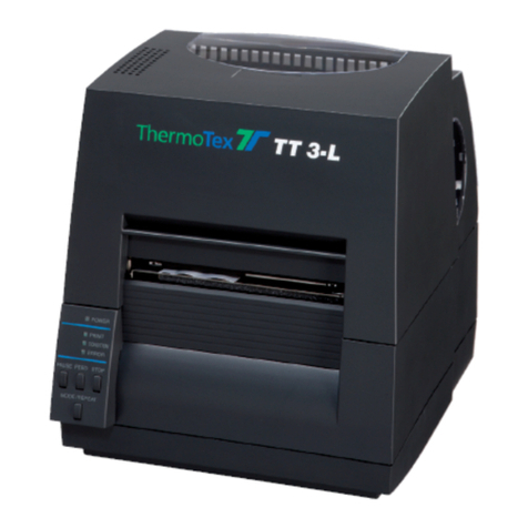
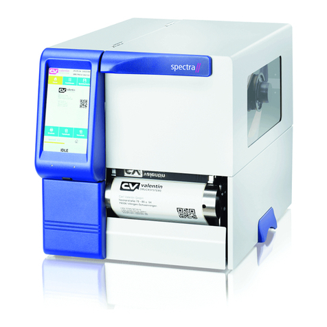
ThermoTex TT4-S User manual

ThermoTex Nagel GmbH
Schutterstraße 14, D-77746 Schutterwald
Tel.: +49 (0)781/9616-0, Fax: +49 (0)781/9616-50
[email protected], www.thermo-tex.de
GBTT4SBA.002
Operating manual for
TT4-S
- Translated version of the original operating manual -

GBTT4SBA
Page - 2
Contents
1Product description.........................................................................................................3
1.1
General description, intended purpose.........................................................................................................3
1.2
Scope of supply.............................................................................................................................................3
1.3
Technical data...............................................................................................................................................4
1.4
Parts of the printer ........................................................................................................................................4
1.5
Properties of the thermo print head ..............................................................................................................5
1.6
Instructions for the lithium battery.................................................................................................................5
1.7
Declaration of conformity..............................................................................................................................6
2Safety instructions...........................................................................................................7
3Initial commissioning......................................................................................................8
3.1
Power connection .........................................................................................................................................8
3.2
Connecting to the computer..........................................................................................................................8
3.3
General information for inserting labels and ink ribbons...............................................................................8
3.4
Inserting labels..............................................................................................................................................9
3.5
Inserting the ink ribbon................................................................................................................................10
3.6
Mounting the cutting device ........................................................................................................................12
4Operation........................................................................................................................13
4.1
Control panel...............................................................................................................................................13
4.2
Symbols ......................................................................................................................................................13
4.3
Energy saving mode ...................................................................................................................................13
4.4
Button functions..........................................................................................................................................14
4.5
Configuration menu.....................................................................................................................................15
5Settings...........................................................................................................................16
6Test functions ................................................................................................................18
7External keyboard..........................................................................................................20
7.1
Keyboard configuration...............................................................................................................................20
8Troubleshooting ............................................................................................................22
9Cleaning..........................................................................................................................25
9.1
General cleaning.........................................................................................................................................25
9.2
Cleaning the printing roller..........................................................................................................................25
9.3
Cleaning the print head...............................................................................................................................25
9.4
Cleaning the label light barrier ....................................................................................................................26
9.5
Cleaning the cutting device.........................................................................................................................27
10 Spare parts list............................................................................................................27

Product description
GBTT4SBA
Page - 3
1 Product description
1.1 General description, intended purpose
The TT4-S is a label printer for both thermotransfer printing and also for thermo direct printing, and offers great
variability in the printing image design.
Thermotransfer printing requires a special ink ribbon together with the label material. The printing image is
produced by heating dots in the ink ribbon with corresponding transfer of the ink particles to the label.
Thermo direct printing is based on using label material with a thermoreactive coating. The printing image is
created by heating dots of the material at the thermo print head, causing corresponding changes in colour to the
coating.
The use of a high-speed 32 bit Coldfire processor with a clock speed of 266MHz and the main memory of 64 MB
produce printing results in a matter of seconds, even for very large labels (up to 2000 mm long). The TT4-S
offers the following interfaces for data transfer:
Interfaces TT4-S
Serial interface RS232 C, 8 bit, 1200-230400 baud
Serial interface RS422/485, 8 bit, 1200-230400 baud
Parallel interface, bi-directional, as per IEEE1284
USB 2.0 high-speed slave (for PC connection)
Ethernet 10/100 Base T, LPD, RawIP-Printing, DHCP, http,
FTP, SMTP, SNMP, NTP
WLAN card 802.11b/g
Twinax/coax converter
2x USB master for keyboard and scanner
= standard, = optional
The printer offers the possibility of using memory cards for permanent storage of graphics, fonts or label
descriptions. To this end, the data can be transferred via the above named interfaces. CompactFlash cards type
I with capacity of up to 1 GB are suitable memory cards.
The unit must only be used for printing labels, continuous paper and similar materials.
Safe operation of the machine cannot be guaranteed if the TT4-S is not used for its
intended purpose.
Compliance with all information in the operating manual is an integral part of proper use.
1.2 Scope of supply
The standard scope of supply includes
•thermotransfer printer TT4-S
•label trough
•operating manual
•driver CD
•empty foil core (mounted on ink ribbon winder)
•power lead
•serial connection lead

Product description
GBTT4SBA
Page - 4
1.3 Technical data
Electrical data
Operating voltage: 230 V / 50 Hz
Power: 200 W
Dimensions
Height: 274 mm
Width: 242 mm
Depth: 446 mm
Weight: 9 kg
Printing unit
Resolution: 300 dpi (standard)
Max. printing width: 105.6 mm
Printing speed: 75...250 mm/s (adjustable)
Ink ribbon
Ink ribbon width: up to 114 mm (the ink ribbon should be at least as wide as the label material,
to protect the print head from wear)
Core diameter: 25 mm
Max. roll diameter: 80 mm
Labels
Width: 4...116 mm
Height: 5-2000 mm
Max. thickness: 0.35 mm
Core diameter: 38...76 mm
Max. roll diameter: 210 mm
Label sensor (transparent light/reflection from below)
Distance to lay edge: 5...53 mm
Control panel (buttons illuminated depending on operating mode)
LCD graphic display WxH: 60x40 in mm
Text lines/digits: 4 / approx. 20
1.4 Parts of the printer
1 Retaining screw
2 Roll guide
3 Roll holder
4 Core adapter 76mm (option)
5 Internal winder (option)
6 Sliding guide ring
7 Label light barrier
8 Hex key
9 Lever for locking print head
10 Lid
Fig. 1-1 - Parts of the printer

Product description
GBTT4SBA
Page - 5
1 Lid
2 Core adapter 76mm (option)
3 Roll guide
4 Roll holder
5 Display
6 Navigator pad
7 Transfer film deflector
8 Printing roller
9 Print head
10 Film winder
11 Film unwinder
Fig. 1-2 - Parts of the printer
1.5 Properties of the thermo print head
The thermo print head is the most delicate part of your printer. Please always comply with
the following instructions.
1. Do not touch the glass safeguard on the print head with your hand. Do not use any sharp objects (knife,
screwdriver, etc.) to clean the print head.
2. During printing, make sure that there are no impurities on the label which could be pulled through under
the print head. These could damage the head.
3. Ensure the label has a good, smooth surface. Rough label surfaces act as sandpaper and reduce the
service life of the head.
4. Clean the head regularly with cotton buds soaked in alcohol.
5. Print at the lowest possible head temperature.
Incorrect handling can damage your print head very quickly.
1.6 Instructions for the lithium battery
The electronic board of your printer is equipped with a lithium battery. Discharged batteries must be disposed of
in corresponding old battery collections. If the batteries are not completely discharged, place adhesive tape over
the poles to prevent short circuits.
When decommissioning the printer, the battery must always be disposed of separately from the rest of the
printer.
5
6
7
8
9
10
11

Product description
GBTT4SBA
Page - 6
1.7 Declaration of conformity
CE Declaration of Conformity
Manufacturer:
ThermoTex Nagel GmbH
Schutterstraße 14
D-77746 Schutterwald
Device description:
Type: TT4-S
Production status: December 2009
The device fulfils the health and safety requirements of the following EC directives:
•Low voltage directive 2006/95/EC
Applied standard: EN 60950-1:2006
•Electromagnetic compatibility directive 2004/108/EC
Applied standards: EN 55022:2006
EN 55024:1998+A1:2001+A2:2003
EN 61000-3-2:2006
EN 61000-3-3:1995+A1:2001+A2:2005
Schutterwald, 17.12.2009
ThermoTex Nagel GmbH
Dietmar Nagel
(Managing Director)

Safety instructions
GBTT4SBA
Page - 7
2 Safety instructions
The following warning symbols are used on the machine and in this operating manual:
Hazard Warning
Warning, dangerous electrical voltage
Warning of cutting injuries
Disconnect from the power supply
Always comply with the following safety instructions to avoid personal injuries or damage to
the printer.
•The printer must only be operated by correspondingly trained and authorised staff who know the manual and
are capable of working accordingly,
•Only connect the unit to a power supply with suitable voltage. The unit is rated for AC voltage from 100 to
240 V. Only connect the printer to a grounded power socket.
•Only connect the printer to units with protective low voltage.
•Ensure that all units being connected (printer, computer etc.) are switched off when connecting together.
Also switch the units off before disconnecting them.
•Ensure that your printer is not exposed to damp or wet conditions.
•The printer can be operated with the lid opened. In this condition, the rotating parts are freely accessible.
Ensure that no hair, jewellery etc. can get caught up in these rotating parts.
•During operation, the print head component can get hot. Beware when touching the component.
•Disconnect the printer from the power supply before starting any cleaning or maintenance work.
•Only qualified maintenance technicians should repair the printer.
Do not open the rear wall! Mortal risk from power supply voltage!

Initial commisioning
GBTT4SBA
Page - 8
3 Initial commissioning
3.1 Power connection
The printer is equipped with a wide-range power unit (100...240V~) so that it can be operated from a power
supply of both 230V~/50Hz and 115V~/60Hz without having to interfere with the printer.
Before connecting your printer to the power supply, make sure that the power switch (1) is
in the "0" (OFF) setting.
1 Power switch
2 Power socket
3 Slot for card bus or PC card type II
4 Slot for CompactFlash memory card
5 Ethernet 10/100 Base-T
6 USB interface for keyboard and/or scanner
7 USB high-speed slave interface
8 Serial RS 232 C interface
Fig. 3-1 - Connecting the printer
Connect the power lead to the power socket (2) and plug the lead into an earthed socket.
3.2 Connecting to the computer
The standard printer has a serial RS-232 interface (8), a USB high-speed interface (7) and an Ethernet 10/100
Base-T interface (5). For a serial connection, the RS-232 interface of the printer must be configured according to
the settings on your computer.
Standard settings on delivery:
Interface Configuration
RS-232 Baud rate: 115200
Parity: none
Flow control: RTS/CTS
Data bits: 8
Stop bits: 1
Ethernet 10/100 Base-T DHCP: on Gateway: off
Connect the computer and printer with a suitable lead and use the screws or straps on the connectors to secure
the lead connection.
3.3 General information for inserting labels and ink ribbons
The various control and adjusting elements inside the printer are marked green or red.
Only the green control elements are required to change a label roll or ink ribbon roll of the same width.
It may be necessary to use the red control elements as well when inserting a label roll or ink ribbon roll of a
different width.

Initial commisioning
GBTT4SBA
Page - 9
3.4 Inserting labels
Fig. 3-2 - Inserting labels Fig. 3-3 - Adjusting the label light barrier
1. Loosen the knurled screw (1), swivel the guide (2) upwards and push it as far as possible to the outside.
2. Place the roll of labels on the roll holder (3) and unwind a longer strip of labels from the main roll. Push the
roll as far as it will go.
3. Swivel the guide (2) down to the roll holder (3). Push the guide against the main roll so that it is braked
slightly when unwinding. Tighten the knurled screw (3).
4. Swivel the lever (9) counter-clockwise as far as it will go, thus lifting the print head component.
5. Push the guide ring (6) outwards as far as it will go.
6. Guide the strip of labels through the printer as shown in Fig. 3-2. The run of paper for labels on the outside
is shown as a continuous line, the run of paper for labels on the inside as a dotted line.
ThermoTex rolls of labels are on the outside, i.e. the side being printed is on the outside. Exception:
ThermoTex fix plastic film: this is on the inside.
7. Adjust the label light barrier (12) so that the actual sensor (11) can register the gap between the labels or
the reflection or perforation marks. To adjust, push the label light barrier into the right position using the
handle (13).
8. Push the guide ring (6) against the outer edge of the strip of labels.
9. Swivel the lever (9) clockwise as far it will go. This locks the print head.
3.4.1 Adjusting the print head pressure
The print head is pressed in position by two tappets. The outer sliding tappet must be adjusted to the width of the
textile tape being used. The sliding tappet must be positioned to produce uniform printing quality. The tappets
can be adjusted to prevent any pleating.
11
12
13

Initial commisioning
GBTT4SBA
Page - 10
1 Setscrew
2 Sliding press-on tappet
3 Lever for locking the print head
4 Ink ribbon defector
Fig. 3-4 - Print head support
1. Turn lever (3) clockwise to lock the print head.
2. Use hex key to loosen the setscrew (1) at the outer tappet (2).
3. Position outer tappet (2) outside the outer edge of the label and tighten the setscrew (1).
3.5 Inserting the ink ribbon
1 Film winder
2 Ink ribbon
3 Film unwinder
4 Lever for locking the print head
Fig. 3-5 - Inserting the ink ribbon
To prevent premature wear to the print head, only use an ink ribbon which is somewhat
wider than the material being printed.
4

Initial commisioning
GBTT4SBA
Page - 11
Do not insert an ink ribbon for thermo direct printing.
1. Swivel the lever (4) counter-clockwise as far as it will go, thus lifting the print head.
2. Push the ink ribbon roller (2) onto the unwinder (3) as far as it will go.
3. Hold the ink ribbon roller and turn the green knob counter-clockwise until you notice a resistance. In this way,
the ink ribbon roller (2) is clamped to the unwinder (3).
4. Push a film core of a suitable width onto the winder (1) and clamp the film core in the same way.
5. Insert the ink ribbon as shown in Fig. 3-5 and adhere the start of the ribbon to the film core with a piece of
adhesive tape. In Fig. 3-5, the continuous line applies to rollers with coated side on the inside, and the dotted
line for rollers with coated side on the outside.
ThermoTex ink ribbons have the coating on the outside.
6. Turn the winder (1) counter-clockwise to make the film run smoothly and tautly.
7. Swivel the lever (4) clockwise as far as it will go. This locks the print head.
3.5.1 Adjusting the ink ribbon guide
1 Scale
2 Adjusting screw
Fig. 3-6 - Adjusting the ink ribbon guide
If pleating should occur in the run of the ink ribbon which can cause faulty print quality, the ink ribbon deflector (4
Fig. 2-4) can be adjusted to correct the fault:
Read off and if necessary note the current setting on the scale (1).
To change the setting, turn the screw (2) with the hex key. Adjust in the "+" direction to tighten the inner edge of
the ink ribbon. Adjust in the "-" direction to tighten the outer edge of the ink ribbon.
To suppress pleating, tighten the ink ribbon at the edge where pleating starts.

Initial commisioning
GBTT4SBA
Page - 12
3.6 Mounting the cutting device
•Disconnect the printer from the power supply before mounting or dismounting the
cutting device!
•A tear-off plate (article no. 15986) must be mounted on the printer. This makes sure
that the label tape is guided properly through the blades of the cutting device.
Fig. 3-7 - Mounting the cutting device
•Attach the cutting device to the printer. The positioning pins (1) fit into the holes (2).
•Push together the two parts in order to connect the plugs (3, 4).
•Tighten the screw (5).
•When the printer is turned on, the cutting device will be detected automatically.
1
5 43
2

Operation
GBTT4SBA
Page - 13
4 Operation
4.1 Control panel
1 Display
2 Navigator pad
Fig. 4-1 - Control panel
The control panel consists of a graphic display (1) and the navigator pad (2) with four integrated buttons.
The control panel display constantly shows information about the system status of the printer and the processing
status of the current print job.
The function of the buttons depends on the corresponding system status. The active functions are marked by
the currently valid wording or symbols which light up in the buttons.
When printing, active functions light up white (e.g. menu or feed).
In the offline menu, active functions light up orange (arrows, ↵button).
4.2 Symbols
Depending on the configuration of the printer, the symbols shown in the table below can appear in the status line
of the display. The operator can thus see the current printer status straightaway.
Symbol Meaning Symbol Meaning
Time
Print head temperature
Date
PPP credit
Status of the main film roll Memory
WLAN field strength Input buffer
Ethernet status Printer receiving data
4.3 Energy saving mode
Symbol Meaning
If the printer is not used for a longer period of time, it automatically switches to the energy saving
mode. The navigator pad lighting is switched off. Press any key on the navigator pad to end the
energy saving mode.

Operation
GBTT4SBA
Page - 14
4.4 Button functions
Button Status Function
menu ready to the offline menu
Feed ready feed of an empty label
pause ready repeat print of the last label
print label interrupt print job
printer goes to pause status
pause continue print job
printer goes to print label status
fault which can be remedied after troubleshooting, continue print job
printer goes to print label status
cancel ready delete print buffer, the last label can no longer be printed after
this
print label
pause
fault which can be remedied
fault which cannot be remedied
press and release →cancel current print job
press and hold →cancel current print job
and delete all print jobs
system error press
contact hotline if error persists
↵button fault which can be remedied
fault which cannot be remedied
go to help function →brief information is shown for remedying
the error
offline menu press and release →select a value in the parameter level, adopt
a selected value or start a function
press and hold (> 2s) →leave parameter level without adopting
parameter setting
offline menu select menu points in a menu level or select values in the
parameter level
press repeatedly in the top menu level to go to the ready status
from the offline menu
offline menu select menu points in a menu level or select values in the
parameter level
offline menu go to a higher or lower menu level or adjust values in the
parameter level

Operation
GBTT4SBA
Page - 15
4.5 Configuration menu
The configuration menu, also called offline menu, has several levels with possibilities for adjusting device and
print parameters, for accessing test and service functions and for handling the memory cards. Go to the menu
by pressing menu in the ready status.
1st menu level 2nd menu level access
memory card load label only with card plugged in
print contents only with card plugged in
copy card only with card plugged in, PIN protection
possible
delete card only with card plugged in, PIN protection
possible
print file contents only with card plugged in
short status
test print status
font list
device list
print head profile
monitor mode
test grid
label profile
settings regional settings PIN protection possible
device settings
print parameters
interfaces
status bar
security
Service
new firmware PIN protection possible
firmware from card PIN protection possible
save settings only with memory card plugged in, PIN
protection possible
load settings

Settings
GBTT4SBA
Page - 16
5 Settings
The "Settings" menu of the offline menu contains a large number of parameters for configuring your printer to
the concrete application. Usually changes are made in this menu mainly during initial commissioning and
following fundamental changes to the operating conditions of the printer. Changes necessary when processing
different print jobs, for example with different materials, can usually be implemented with the software settings.
The complete "Settings" menu can be protected from unauthorised access by a code number (PIN).
PIN "0000" is adjusted as standard code number for TT4-S.
1. Press menu in the "ready" state to go to the offline menu.
2. Keep pressing until the "Settings" menu appears. Press ↵.
3. If the "Settings" menu is protected by a PIN, the following input request appears in the display: "PIN: 0000".
Press and to change the individual digits of the PIN. The digit being changed flashes in the display and
can be selected with and. Press ↵to accept the input. When all digits have been entered correctly, the
program goes to the "Settings" menu.
4. The parameters are organised in a tree structure. Press or to make your selection between the individual
sub-menus. Press ↵to go to the selected sub-menu.
5. On reaching the individual parameter level, the current value of the selected parameter appears in the display
under the parameter name. Press ↵to change the value of a parameter. Press andto adjust the
parameter. Press ↵to adopt the value and leave the parameter level.
6. To return to the superordinate menu or to the "ready" state, press several times and press in the first
menu level. Pressing ↵for 2 seconds achieves the same effect.
The following table provides a brief overview of the configuration parameters.
Settings - Regional settings
Parameter Meaning Default
Country Display language, time and date format Germany
Timezone Time zone as per UTC (Universal Time Coordinated) UTC+1
Summer time Method for adjusting the summer time EU
Set the date Setting the date Current date
Set the time Setting the time Current time
Settings - Unit settings
Parameter Meaning Default
Print head offset X Offset of the printed image in the label crosswise to the print
direction 0.0 mm
Print head offset Y Offset of the printed image in the label in the print direction 0.0 mm
Tear-off position Parameter for changing the tear-off position 0.0 mm
[Dispenser edge] Parameter for dispenser light barrier (option) -
[Blade] Parameter for cutting blade 0.0 mm
Brightness LCD Brightness of the background lighting of the display 10
Contrast LCD Optimising the legibility of the display 6
Energy sav. delay Delay for changing to the energy saving mode 5 min
Debug mode Activating the debug mode off
Settings –-Print parameters
Parameter Meaning Default
Heating energy Basic setting for print intensity (blackening) 0
Printing rate Basic setting for printing rate 75 mm/s
Transfer print Basic setting thermo transfer/thermal direct print ON/OFF On
Film advance
warning Advance warning when remaining film diameter less than defined
amount Off
Label sensor Label detection continuous transparent light/reflection from below Transparent light
Tear-off position Additional feed at job end ON/OFF Off
Return transport Return transport optimised/always for cutting/dispensing mode Optimised

Settings
GBTT4SBA
Page - 17
Fault – reprint Choice of reprinting a faulty label after eliminating the fault On
Pause – reprint Possibility of printing more labels after the end of the job by pressing
pause Off
Barcode error Printing interrupted for faulty barcode contents ON/OFF On
Wide monitor mode
Definition of printing area for monitor mode test function Automatic
Settings - Interfaces
Parameter Meaning Default
Set of characters Selection of characters table Windows 1252
RS-232 Baud rate / protocol setting 115200, RTS/CTS
Ethernet Configuration of the Ethernet interface -
DHCP Method of issuing the IP address ON/OFF On
IP Fixed IP address (only valid for DHCP = OFF) -
Mask SubNet mask of the local net (only valid for DHCP = OFF) -
Gateway Connection address between local and other networks Off
Network error Error status for network problems ON/OFF Off
Settings – Status bar
Parameter Meaning Default
Clock Display in status bar ON/OFF On
Calendar page Display in status bar ON/OFF On
Film stock Display in status bar ON/OFF Off
WLAN field
strength Display in status bar ON/OFF Off
Ethernet status Display in status bar ON/OFF Off
Temperature Display in status bar ON/OFF Off
Credit Display in status bar ON/OFF Off
ABC debug Display in status bar ON/OFF Off
User memory Display in status bar ON/OFF Off
Input buffer Display in status bar ON/OFF Off
Card access Display in status bar ON/OFF Off
Data transfer Display in status bar ON/OFF On
Settings - Safety
Parameter Meaning Default
PIN Setting, deleting and changing a code number to protect certain
functions and settings 0000

Test functions
GBTT4SBA
Page - 18
6 Test functions
The printer has a series of test functions under the "Test" menu of the offline menu.
1. Press menu to go from "ready" to the offline menu.
2. Press to select "Test". Press for the level of the test functions.
3. Pressand to select the required test function and press ↵to confirm.
For all test functions entailing printing, please insert material which covers the complete printing
width.
Test
Brief status
Shows the main configuration and operation parameters in the display
Press and to change over between the parameter displays. Press ↵to leave the status display.
Status printout
Printout of the main configuration and operating parameters, together with a test sample for checking
print quality (Fig. 6-1).
Fonts list
Printout of a list with the main parameters of the fonts available in the printer. The list contains both
internal printer fonts and also the loaded fonts (Fig. 6-2).
Devices list
Printout of a list of the main hardware components installed in the printer and the connected optional
devices (Fig. 6-3).
Print head profile
Printout of a curve diagram showing the resistance values of the heated points in the print head.
Increasing resistance values indicate a damaged or defect printing point.
Monitor mode
Printout of the control sequences received from the computer. The print job is sent after changing to
the monitor mode. The incoming print commands are not interpreted (Fig. 6-4), but printed out as text
(Fig. 6-5). Press cancel to leave the monitor mode.
Test grid
Printout of a test sample for assessing print quality.
Label profile
Printout of a curve diagram showing the values measured by the label sensor during material transport.

Test functions
GBTT4SBA
Page - 19
Fig. 6-1 - Status printout
Fig. 6-2 - Fonts list Fig. 6-3 - Devices list
Fig. 6-4 - Example label "normal" printing Fig. 6-5 - Example label in monitor mode

External keyboard
GBTT4SBA
Page - 20
7 External keyboard
All MF-2 compatible USB keyboards supporting code set 3 can be used.
The keyboard is connected to the corresponding socket on the back of the printer.
7.1 Keyboard configuration
The printer is adjusted to the corresponding national keyboards using the settings of the configuration parameter
"Country". The printer has a modified keyboard configuration table for every adjustment of this parameter, which
is generally based on the DOS configuration.
The button [ALT GR] has no function. Instead, all characters shown on the buttons to the right of the normal
characters (e.g. { } [ ] \ ) are accessed with [ALT]. Various special characters (e.g. × ÷ ) are also accessed using
[ALT].
Table 7-1
/ , * , ... buttons in the numerical block
GR: Deutschland FR: France UK: United Kingdom US: USA
SG: Schweiz SF: Suisse BE: Belgie SU: Suomi
IT: Italia SP: España DK: Danmark CZ: Ceska republika
Other special characters (e.g. œ ñ ç) can be accessed by entering two characters in succession: press [ALT] in
each case before entering the second character.
Table 7-2
Table of contents
Other ThermoTex Label Maker manuals
